EP1892043A2 - Vorrichtung zur analyse von körperflüssigkeit - Google Patents
Vorrichtung zur analyse von körperflüssigkeit Download PDFInfo
- Publication number
- EP1892043A2 EP1892043A2 EP07122841A EP07122841A EP1892043A2 EP 1892043 A2 EP1892043 A2 EP 1892043A2 EP 07122841 A EP07122841 A EP 07122841A EP 07122841 A EP07122841 A EP 07122841A EP 1892043 A2 EP1892043 A2 EP 1892043A2
- Authority
- EP
- European Patent Office
- Prior art keywords
- cartridge
- hatch
- storage
- stick
- incubator
- Prior art date
- Legal status (The legal status is an assumption and is not a legal conclusion. Google has not performed a legal analysis and makes no representation as to the accuracy of the status listed.)
- Withdrawn
Links
Images





























Classifications
-
- B—PERFORMING OPERATIONS; TRANSPORTING
- B01—PHYSICAL OR CHEMICAL PROCESSES OR APPARATUS IN GENERAL
- B01L—CHEMICAL OR PHYSICAL LABORATORY APPARATUS FOR GENERAL USE
- B01L9/00—Supporting devices; Holding devices
- B01L9/52—Supports specially adapted for flat sample carriers, e.g. for plates, slides, chips
-
- B—PERFORMING OPERATIONS; TRANSPORTING
- B01—PHYSICAL OR CHEMICAL PROCESSES OR APPARATUS IN GENERAL
- B01L—CHEMICAL OR PHYSICAL LABORATORY APPARATUS FOR GENERAL USE
- B01L3/00—Containers or dishes for laboratory use, e.g. laboratory glassware; Droppers
- B01L3/50—Containers for the purpose of retaining a material to be analysed, e.g. test tubes
- B01L3/508—Rigid containers without fluid transport within
-
- G—PHYSICS
- G01—MEASURING; TESTING
- G01N—INVESTIGATING OR ANALYSING MATERIALS BY DETERMINING THEIR CHEMICAL OR PHYSICAL PROPERTIES
- G01N21/00—Investigating or analysing materials by the use of optical means, i.e. using sub-millimetre waves, infrared, visible or ultraviolet light
- G01N21/84—Systems specially adapted for particular applications
- G01N21/86—Investigating moving sheets
-
- G—PHYSICS
- G01—MEASURING; TESTING
- G01N—INVESTIGATING OR ANALYSING MATERIALS BY DETERMINING THEIR CHEMICAL OR PHYSICAL PROPERTIES
- G01N33/00—Investigating or analysing materials by specific methods not covered by groups G01N1/00 - G01N31/00
- G01N33/02—Food
- G01N33/04—Dairy products
-
- G—PHYSICS
- G01—MEASURING; TESTING
- G01N—INVESTIGATING OR ANALYSING MATERIALS BY DETERMINING THEIR CHEMICAL OR PHYSICAL PROPERTIES
- G01N35/00—Automatic analysis not limited to methods or materials provided for in any single one of groups G01N1/00 - G01N33/00; Handling materials therefor
- G01N35/00029—Automatic analysis not limited to methods or materials provided for in any single one of groups G01N1/00 - G01N33/00; Handling materials therefor provided with flat sample substrates, e.g. slides
-
- B—PERFORMING OPERATIONS; TRANSPORTING
- B01—PHYSICAL OR CHEMICAL PROCESSES OR APPARATUS IN GENERAL
- B01L—CHEMICAL OR PHYSICAL LABORATORY APPARATUS FOR GENERAL USE
- B01L2300/00—Additional constructional details
- B01L2300/06—Auxiliary integrated devices, integrated components
- B01L2300/0681—Filter
-
- B—PERFORMING OPERATIONS; TRANSPORTING
- B01—PHYSICAL OR CHEMICAL PROCESSES OR APPARATUS IN GENERAL
- B01L—CHEMICAL OR PHYSICAL LABORATORY APPARATUS FOR GENERAL USE
- B01L2300/00—Additional constructional details
- B01L2300/08—Geometry, shape and general structure
- B01L2300/0809—Geometry, shape and general structure rectangular shaped
- B01L2300/0819—Microarrays; Biochips
-
- B—PERFORMING OPERATIONS; TRANSPORTING
- B01—PHYSICAL OR CHEMICAL PROCESSES OR APPARATUS IN GENERAL
- B01L—CHEMICAL OR PHYSICAL LABORATORY APPARATUS FOR GENERAL USE
- B01L2300/00—Additional constructional details
- B01L2300/08—Geometry, shape and general structure
- B01L2300/0809—Geometry, shape and general structure rectangular shaped
- B01L2300/0822—Slides
-
- B—PERFORMING OPERATIONS; TRANSPORTING
- B01—PHYSICAL OR CHEMICAL PROCESSES OR APPARATUS IN GENERAL
- B01L—CHEMICAL OR PHYSICAL LABORATORY APPARATUS FOR GENERAL USE
- B01L2400/00—Moving or stopping fluids
- B01L2400/04—Moving fluids with specific forces or mechanical means
- B01L2400/0403—Moving fluids with specific forces or mechanical means specific forces
- B01L2400/0406—Moving fluids with specific forces or mechanical means specific forces capillary forces
-
- B—PERFORMING OPERATIONS; TRANSPORTING
- B01—PHYSICAL OR CHEMICAL PROCESSES OR APPARATUS IN GENERAL
- B01L—CHEMICAL OR PHYSICAL LABORATORY APPARATUS FOR GENERAL USE
- B01L3/00—Containers or dishes for laboratory use, e.g. laboratory glassware; Droppers
- B01L3/50—Containers for the purpose of retaining a material to be analysed, e.g. test tubes
- B01L3/502—Containers for the purpose of retaining a material to be analysed, e.g. test tubes with fluid transport, e.g. in multi-compartment structures
-
- B—PERFORMING OPERATIONS; TRANSPORTING
- B01—PHYSICAL OR CHEMICAL PROCESSES OR APPARATUS IN GENERAL
- B01L—CHEMICAL OR PHYSICAL LABORATORY APPARATUS FOR GENERAL USE
- B01L3/00—Containers or dishes for laboratory use, e.g. laboratory glassware; Droppers
- B01L3/50—Containers for the purpose of retaining a material to be analysed, e.g. test tubes
- B01L3/502—Containers for the purpose of retaining a material to be analysed, e.g. test tubes with fluid transport, e.g. in multi-compartment structures
- B01L3/5023—Containers for the purpose of retaining a material to be analysed, e.g. test tubes with fluid transport, e.g. in multi-compartment structures with a sample being transported to, and subsequently stored in an absorbent for analysis
-
- G—PHYSICS
- G01—MEASURING; TESTING
- G01N—INVESTIGATING OR ANALYSING MATERIALS BY DETERMINING THEIR CHEMICAL OR PHYSICAL PROPERTIES
- G01N35/00—Automatic analysis not limited to methods or materials provided for in any single one of groups G01N1/00 - G01N33/00; Handling materials therefor
- G01N35/00029—Automatic analysis not limited to methods or materials provided for in any single one of groups G01N1/00 - G01N33/00; Handling materials therefor provided with flat sample substrates, e.g. slides
- G01N2035/00039—Transport arrangements specific to flat sample substrates, e.g. pusher blade
- G01N2035/00049—Transport arrangements specific to flat sample substrates, e.g. pusher blade for loading/unloading a carousel
-
- G—PHYSICS
- G01—MEASURING; TESTING
- G01N—INVESTIGATING OR ANALYSING MATERIALS BY DETERMINING THEIR CHEMICAL OR PHYSICAL PROPERTIES
- G01N35/00—Automatic analysis not limited to methods or materials provided for in any single one of groups G01N1/00 - G01N33/00; Handling materials therefor
- G01N35/00029—Automatic analysis not limited to methods or materials provided for in any single one of groups G01N1/00 - G01N33/00; Handling materials therefor provided with flat sample substrates, e.g. slides
- G01N2035/00089—Magazines
-
- G—PHYSICS
- G01—MEASURING; TESTING
- G01N—INVESTIGATING OR ANALYSING MATERIALS BY DETERMINING THEIR CHEMICAL OR PHYSICAL PROPERTIES
- G01N35/00—Automatic analysis not limited to methods or materials provided for in any single one of groups G01N1/00 - G01N33/00; Handling materials therefor
- G01N35/00029—Automatic analysis not limited to methods or materials provided for in any single one of groups G01N1/00 - G01N33/00; Handling materials therefor provided with flat sample substrates, e.g. slides
- G01N2035/00099—Characterised by type of test elements
- G01N2035/00108—Test strips, e.g. paper
-
- G—PHYSICS
- G01—MEASURING; TESTING
- G01N—INVESTIGATING OR ANALYSING MATERIALS BY DETERMINING THEIR CHEMICAL OR PHYSICAL PROPERTIES
- G01N35/00—Automatic analysis not limited to methods or materials provided for in any single one of groups G01N1/00 - G01N33/00; Handling materials therefor
- G01N2035/00346—Heating or cooling arrangements
- G01N2035/00356—Holding samples at elevated temperature (incubation)
-
- G—PHYSICS
- G01—MEASURING; TESTING
- G01N—INVESTIGATING OR ANALYSING MATERIALS BY DETERMINING THEIR CHEMICAL OR PHYSICAL PROPERTIES
- G01N35/00—Automatic analysis not limited to methods or materials provided for in any single one of groups G01N1/00 - G01N33/00; Handling materials therefor
- G01N35/02—Automatic analysis not limited to methods or materials provided for in any single one of groups G01N1/00 - G01N33/00; Handling materials therefor using a plurality of sample containers moved by a conveyor system past one or more treatment or analysis stations
- G01N35/04—Details of the conveyor system
- G01N2035/0439—Rotary sample carriers, i.e. carousels
- G01N2035/0444—Rotary sample carriers, i.e. carousels for cuvettes or reaction vessels
-
- G—PHYSICS
- G01—MEASURING; TESTING
- G01N—INVESTIGATING OR ANALYSING MATERIALS BY DETERMINING THEIR CHEMICAL OR PHYSICAL PROPERTIES
- G01N35/00—Automatic analysis not limited to methods or materials provided for in any single one of groups G01N1/00 - G01N33/00; Handling materials therefor
- G01N35/10—Devices for transferring samples or any liquids to, in, or from, the analysis apparatus, e.g. suction devices, injection devices
- G01N35/1009—Characterised by arrangements for controlling the aspiration or dispense of liquids
- G01N35/1016—Control of the volume dispensed or introduced
- G01N2035/1018—Detecting inhomogeneities, e.g. foam, bubbles, clots
Definitions
- the present invention relates generally to an apparatus for analysing fluid taken from a body, and more in particularly for analysing body fluids from mammals.
- the apparatus provides an automated analysis of milk.
- the invention further relates to a method for performing an analysis of body fluids.
- analysis instruments have been used in the dairy industry for optimising the production and for quality assurance at all stages along the production line at the dairies.
- the analysis instruments are usually installed in special analysing rooms where the environment usually is not so harsh to the equipment or the biosensors that are needed in the process.
- Performing the analysis late in the production process may results in many problems for the reason that if a milk sample is bad it already have been mixed in a larger batch and thus the whole batch might have to be wasted due to this. Moreover storage space and transportation space is wasted because of transportation of bad milk, thus the logistic is not as effective as it could be.
- the present invention addresses the above-described problems and hence provides a solution wherein it is possible to achieve different internal environment(s) inside an analysis apparatus compared to the environment wherein the analysis apparatus is located. Furthermore it may be possible to achieve even two or more different internal environments. The internal environments may also be different from each other.
- Preferred embodiments of the apparatus comprise storage for storing sticks or other kinds of biosensors, an incubator and transferring means for moving sticks from storage to incubator.
- the incubator comprises an incubator transport, for example an incubator disc on which the sticks are to be loaded.
- the apparatus performs the steps of loading the sticks on to the incubator disc, thermal conditioning of the sticks, dosing of the body fluid, incubation of the sticks carrying the body fluid and analysing the result. Finally the sticks are automatically removed from the incubator disc into a waste container.
- the present invention relates to an apparatus for analyzing chemical contents in a body fluid sample.
- the main parts of the apparatus are preferably:
- the invention described above preferably relates to a technical system and associated methods for analyzing body fluid.
- an apparatus for analysing fluid taken from a body comprising at least one storage storing sticks and/or other kinds of biosensors to which the fluid is to be dosed, at least one incubator being distinct from the storage and transfer means for transferring sticks from the storage to the incubator.
- an optical reader for reading the degree of chemical reaction found on test sticks, the optical reader comprising; at least one image sensor capable of capturing images, at least one lens, at least one memory, at least one illumination source, and a controller.
- a housing for an optical reader comprises outer walls forming the housing, a front end facing a test stick and a back end, the housing further comprises; an image sensor capable of capturing still or motion images, at least one lens, and at least one opening in the outer walls for image capturing, wherein the front end comprises the at least one opening.
- a computer system for controlling an optical reader for reading test sticks comprises; a first illumination source for illumination of the test sticks, a second illumination source for illumination of the test sticks, at least one lens, outer walls forming a housing, and at least one opening in the outer walls for image capturing, inner screening walls for screening off light, and a transportation mechanism for transporting test stick in to an object field
- the computer system comprises; an internal bus, at least one image sensor capable of capturing still or motion images, a controller, an illumination source driver, a processor, a memory, Internal signal interface, and External signal interface, the computer system being characterised in that the controller synchronises the image capture sensor with the movement of the transportation mechanism.
- a cartridge keeper for storing of the cartridges in a storage device
- the cartridge keeper comprises: a housing defining a storing pit for a cartridge, said housing comprises: a charge opening for receiving said cartridges, a bottom, side walls, a plunger for supporting a movable bottom plate in said cartridge, at least one internal spring device for asserting a force on to the plunger, and mounting means for mounting of the cartridge keeper into the storage device.
- a stickmover for moving a stick between two positions, the stickmover comprises a motor, at least one gearwheel, a slide, a pawl that manoeuvre the stick, a pawl lifter, and a coulisse comprising tracks for guiding of the pawl lifter, wherein the pawl and the pawl lifter is mounted to the slide by hinges.
- a reload hatch for loading cartridges into an analysis instrument, wherein the reload hatch comprises a flipper for pushing a cartridge keeper comprising a cartridge into position in a storage carousel and a retractor for retracting the flipper.
- a method for minimising carry over in a dosage system comprising at least one dosage pump, a mainline comprising a valve and a drain, a pipe (dosage line) leading to a dosage unit, the dosage unit comprises at least one needle, a drain funnel and a dosage position, the method comprises the steps of:
- a method for dosing a first liquid sample on to a test stick using a dosage pump, a second liquid and a dosage head comprising a dosage needle comprises the steps of:
- a waste storage device for used sticks comprising:
- the incubator in the apparatus may furthermore comprise first fluid dosing means for dosing the body fluid to be analysed to a stick.
- first fluid dosing means for dosing the body fluid to be analysed to a stick.
- the apparatus may furthermore comprising second dosing means for dosing other fluids to the sticks and/or biosensors.
- the second dosing means may preferably be located inside the incubator similar to the first dosing means.
- the apparatus may furthermore comprise thermostation means for heating and cooling of the incubator. In this way it is easier to achieve a more stable environment inside the incubator.
- thermostation means for heating and cooling. By having this it is easier to achieve a stable storage environment for the sticks.
- the incubator may further comprise reading means for detection of a signal produced on a stick or biosensor after application of the fluid.
- the reading means comprises an image chip.
- the incubator may comprises stick removal means. In order to remove used sticks and make place for new sticks.
- the incubator may further comprise an incubator disc comprising means for positioning, keeping and guiding sticks during the incubation.
- the means may also be called guiding means.
- the guiding means for positioning and guiding sticks are preferably made of plastic but may be manufactured in other materials such as metal or rubber.
- the means comprises a slit in the side wherein the stick is guided.
- the slit may have one or two slopes in order to facilitate the insertion of a stick into the slit.
- the guiding means may have two embodiments one where the stick is guided between the guiding mean and the incubator disc and one wherein the stick is guided only by the guiding mean since the slit is located a bit from the side facing the incubator disc.
- the stick may adhere to the incubator disc because of static electricity. This can be avoided by guiding the stick only by the guiding means.
- using the incubator slot as part of the guiding means will give a shorter tolerance chain towards the optical reader.
- the storage comprises a storage disc.
- a substantially circular storage it is easier for a user to access thus load and unload the storage from one opening.
- the storage comprises means for rotation of the storage disc.
- Some examples may be electric motors such as a stepmotor or the alike.
- the incubator is preferably rotated by an electric motor, such as a stepmotor.
- the apparatus may furthermore comprise means for monitoring the number of used sticks.
- Such means may be different kind of sensors such as photo sensors, mechanical sensors etc.
- molecular sieve or other desiccant type are preferably used.
- conditioning of ammonia and hydrogen sulphide content in the storage is preferably performed in the same way such as with a molecular sieve or other desiccant type.
- the molecular sieve is mounted in a cartridge for usage in the apparatus.
- the apparatus preferably comprises computer means for controlling the different processes and functions such as transportation of sticks, analysis of the reaction on the stick and error alarms etc.
- a user interface comprising at least one of the following;
- the rotating means may be variable rotating means such as electric motors for controlling the rotation speed of the storage transport or incubator transport, preferably the storage and incubator transports are circular such as a storage disc and an incubator disc.
- rotating means for the storage and incubator transports are step motors facilitating a precise positioning of the storage transport and incubator transport.
- the storage and the incubator are preferably thermally isolated from each other and/or isolated so as to avoid or limit humidity and/or heat exchange between the storage and the incubator. In this way it is easier to keep the right storage condition in the storage wherein the sticks can be stored longer without losing their function.
- the apparatus comprises a dosage system driven by a spindle or other linear or rotational system, for dosing body fluid at one or more locations, preferably at least at two different locations.
- the apparatus preferably comprises a protection towards the outer environment, the protection preferably comprises a main cabinet, an outer top cover and insulation enclosures, creating a double sealing.
- the apparatus may comprise means for cooling and or heating such as a central conditioning system.
- the apparatus comprises sensors for different functions such as sensors for checking that hatches has been closed correctly etc.
- the apparatus comprises at least one sensor in the stickmover for monitoring the transferring of a stick to the incubator disc.
- the apparatus comprises at least one sensor for monitoring the position of a stick in the incubator disc so that the stick is positioned correctly.
- the apparatus preferably comprises tubes for transportation of fluid samples.
- the tubes may preferably be made of rubber or plastic or any other material suitable for transportation of fluids.
- the apparatus may comprise an air inlet valve(s) in order to provide a system for minimising carry over from a first sample to a second sample.
- an air pump enters air into the tubes in between samples.
- the air is entered into the tubes in a last part of the first sample or in a first part of the second sample.
- the apparatus comprises pumps for moving the fluid samples in the tubes.
- the apparatus comprises bubble detectors for detection of bubbles and thus for management of fluid samples.
- a method for analysing of fluid which utilises an apparatus according to the invention, wherein at least one rotation of the incubator disc or incubator transport comprises the steps of:
- the apparatus may furthermore comprise an optical reader for reading the degree of chemical reaction found on test sticks, preferably the optical reader comprises;
- the apparatus may comprise a housing for an optical reader, the housing preferably comprises outer walls forming the housing, a front end facing a test stick and a back end, the housing may further comprise;
- the housing protects the optical reader from influence from the environment, such as light, temperature etc.
- the apparatus preferably comprises a computer system for controlling an optical reader for reading test sticks.
- the computer system comprises;
- the controller preferably synchronises an image capture sensor with the movement of a transportation mechanism such as an incubator disc, stickmover or storage disc.
- the apparatus preferably comprises at least one cartridge keeper for storing of the cartridges in a storage device, the cartridge keeper comprises:
- the apparatus preferably comprises a stickmover for moving a stick between two positions, such as between the storage and incubator.
- the stickmover comprises a motor, at least one gearwheel, a slide, a pawl that manoeuvre the stick, a pawl lifter, and a coulisse comprising tracks for guiding of the pawl lifter.
- the pawl and the pawl lifter are preferably mounted to the slide by hinges.
- the apparatus may furthermore comprise a reload hatch for loading cartridges into the apparatus, wherein the reload hatch may comprise a flipper for pushing a cartridge keeper comprising a cartridge into position in a storage carousel and a retractor for retracting the flipper.
- the reload hatch may comprise a flipper for pushing a cartridge keeper comprising a cartridge into position in a storage carousel and a retractor for retracting the flipper.
- the apparatus preferably comprise a waste storage device for used sticks, the storage device preferably compriss:
- the hatch cover is connected to the motor by a spring or other flexible element so that it can flex if something gets stuck in the waste opening.
- the optical reader comprised in the apparatus or analysis instrument as described earlier preferably comprises a movable lens. This facilitates the calibration of the system and thus makes it more user friendly.
- the optical reader preferably comprising a first illumination source and a second illumination source.
- the illumination sources may be used depending on what kind of sticks that are to be analysed. Furthermore one stick may be read twice, first illuminated by the first source and then illuminated by the second source. This may give a more accurate reading result.
- the illumination sources are preferably Light Emitting Diodes. However any other kind of light sources may be used.
- the first illumination source emits light of a specific wavelength, different from the wavelength of the light of the second illumination source.
- the controller preferably comprises a processor adapted to image processing, so that the processing of images is performed as fast as possible.
- the memory related to the optical reader preferably comprises at least one flash memory.
- the memory preferably comprises at least one RAM and one flash memory
- the apparatus preferably comprises an internal data bus to which at least the image sensor, the controller and the memory is connected.
- the other devices that needs to communicate with the controller for synchronisation of reading sticks in the apparatus are preferably also connected to the controller.
- the controller further comprises an illumination source driver for controlling the on/off switching of the illumination sources.
- the illumination sources are preferably connected to the illumination source driver.
- the optical reader housing preferably comprises a lens tube in which the lens can move back and forth. Furthermore the lens tube may comprise a second and a third lens in order to achieve more possibilities for focusing and thus change the distance between the stick to be read and the image sensor.
- the housing comprises one or more illumination sources as described above.
- the housing may comprise inner screening walls. These walls make it possible to direct and/or reflect the light inside the housing so as to achieve the best illumination of the area to be illuminated.
- the lens tube is mounted inline with the at least one opening in the housing and the image sensor.
- the illumination sources are preferably positioned relatively to each other on opposite side of the lens tube. In order to achieve the same illumination effect on the illuminated sticks from both the illumination sources.
- the illumination source is positioned so that no direct light can reach the image sensor.
- this may be achieved by using screening walls in order to direct and/or reflect the light.
- the at least one opening is preferably covered by a transparent membrane. In this way the electronics inside the reader housing is protected from environmental influences.
- the at least one lens inside the lens tube may preferably be movable in order to facilitate calibration and user-friendliness
- the housing may preferably comprise illumination sources wherein the first illumination source emits light of a specific wavelength, different from the wavelength of the light of the second illumination source.
- More over the housing may comprise a filter comprising at least two colours.
- This embodiment can be used wherein the illumination sources emits light of the same wavelength.
- the filter is preferably synchronised whit the incubator through the controller so that it can change and thus illuminate the stick with a light that relates to the specific filter.
- the filter may be the membrane covering the at least one opening in the housing and facing the stick to be read.
- the housing may furthermore comprise reflectors for reflecting light from the illumination source towards the stick to be illuminated.
- the computer system described above comprises a controller for preferably controlling the illumination source driver.
- the controller may synchronises the image sensor and the illumination source driver with the transportation mechanism.
- the transportation mechanism is a rotating disc.
- the computer system preferably comprises a database for storage of reference objects. In this way the system can check the image taken by the image sensor and compare it with earlier taken images or reference images in order to achieve a more accurate result.
- the method for reading the amount of chemical reaction found on a test stick may comprise at least some of the following steps or all of them:
- the request sent by the transport mechanism or the incubator may comprise a specified object type and an illumination wavelength.
- a specified object type For example the type of stick and hence which of the illumination sources that should be used, or if both the illumination sources should be used.
- the cartridge keeper described above preferably comprises a spring device in the vicinity of the charge opening and mounted onto the side of one of the halves, for preferably interacting with an upper storage disc, thus holding the cartridge keeper in position in the storage device.
- the cartridge keeper preferably comprises mounting means such as hinges in the vicinity of the bottom of the keeper. In this way the keeper may be tilted out from the storage mechanism such as a storage carrousel.
- the cartridge keeper may comprise retaining means for holding the cartridge in a loading position during the loading into an analysis instrument.
- the retaining means may be plastic protrusions mounted on a flexible part of the cartridge keeper.
- the protrusions preferably interacts with a slit, hole or opening in a cartridge.
- the cartridge keeper may comprise at least one external spring device in the vicinity of the bottom, for providing a tilting force on to the cartridge keeper when it is mounted in a storage mechanism in an analysis instrument.
- the cartridge keeper may comprise an internal bottom-stop for preventing the cartridge to be inserted too far.
- the bottom-stop can move between two positions in order to push the cartridge against a bottom of a storage top disc.
- the bottom-stop preferably has a cavity for receiving the plunger, and one abutment surface on each side of the cavity for abutting the cartridge when the cartridge is being stored in the storage keeper pit.
- the bottom-stop preferably comprises a cavity on the opposite side of the bottom-stop in relation to the abutment surfaces, for receiving a spring which provides the necessary force for pushing the cartridge against the bottom of a storage top disc.
- the cartridge keeper preferably comprises at least two internal guide tracks for guiding the bottom stop in the same direction as the plunger is moving. By having these tracks the movement of the bottom-stop becomes much more stable. Hence, errors during loading/unloading etc are avoided.
- the housing preferably comprises at least one hole in one of the walls for receiving an engagement protrusion integrated in the bottom-stop.
- the bottom-stop can move between two positions defined by the hole in the wall or by the hole in the wall and the bottom of the storage keeper.
- the bottom-stop is forced towards the top position by a spring so that when the cartridge keeper is not loaded the bottom-stop is in an upper position and when it is loaded the bottom-stop is in a lowered position.
- the cartridge keeper comprises a housing, which is preferably made of two halves.
- the top of the two halves are inclined away from each other in order to facilitate the loading of a cartridge.
- the two halves are mounted by screw means in order to facilitate maintenance of the cartridge keepers and the devices mounted inside the keepers.
- the internal spring device for the plunger is mounted in the bottom of the housing, so as to provide the longest possible way for the plunger to move.
- the internal spring device preferably comprises:
- the rod may have at least one stop-device in the second end.
- the first end of the rod is mounted in the vicinity of the bottom of the cartridge keeper.
- the rods are preferably the devices mounted in the bottom of the housing as described above.
- the internal spring device preferably comprises a plunger device movable mounted on the rod between the spring and the stop means.
- the plunger are preferably movable mounted to two rods between the spring and the stop means as described above.
- the second end of the at least one rod may further comprises two incisions for receiving locking means.
- These locking means may be bricks that locks the rod to the bottom of the cartridge keeper.
- the bricks are preferably attached on opposite sides of the bottom.
- the slide described above may preferably comprises teeth's for propulsion of the slide. Hence the teeth's interacts with a gearwheel mounted on a motor.
- the pawl for pushing sticks is preferably flexible or hinged and spring loaded, so that it can follow a guide ramp on a cartridge.
- the pawl is preferably resilient suspended to the slide so that it can follow a guide ramp on a cartridge.
- the stickmover may preferably comprise a hatch for closing and opening a guide tunnel wherein the hatch is mechanically connected to the closing and opening device.
- the hatch prevents air etc to travel from the storage to the incubator or vice versa.
- the closing and opening device described above comprises a protrusion for interacting with the slide, so that when the slides moves it pushes the protrusion which is mechanically connected to the hatch, so that the hatch opens.
- the pawl preferably comprises an incision for receiving slides.
- the part that interacts with the slides is preferably designed so that it fits with the design of the slides. Hence it provides a more secure catch, movement and release of the slides.
- the tracks in the coulisse preferably comprise a flexible track changer for steering of the pawl lifter.
- the pawl lifter When the stickmover moves a stick towards the incubator the pawl lifter preferably passes under the flexible track changer, on the return path the pawl lifter preferably passes on the upper side of the track changer and is thus steered to a different track.
- the guide tunnel or stickmover tunnel, in which the sticks are transported on their way from the storage to the incubator may preferably comprise at least one sensor for monitoring if the pawl moves a stick or not.
- the reload hatch described above may preferably comprise sensor means for securing that the hatch has been securely closed. If the hatch is not securely closed the stored sticks may be destroyed, hence the result from the analysis may come out wrong.
- the hatch preferably comprise a lock arrangement for guiding the hatch the last distance to a closed position. This is done automatically, the user only closes the hatch to an almost closed position wherein the mechanics inside the apparatus is able to interact with the hatch and close it to a closed position.
- the lock arrangement preferably comprises a motor and a locking pawl for closing the hatch.
- the locking pawl engages with the hatch when the hatch is nearly closed by a user.
- the locking pawl is preferably moved to close the hatch, by a motor with a gearwheel that engages with a teeth rack.
- the reload hatch preferably comprise guiding means for guiding a storage keeper.
- guiding means guides the storage keeper down to a load or unload position depending on if the storage keeper contains a cartridge or not.
- the load and unload position is the same.
- the reload hatch preferably comprising a release arm for actuating a keeper spring mounted to the keeper, which holds the keeper in position in the storage carousel.
- the reload hatch may preferably comprise a depressor arm for pushing the cartridge down into the keeper.
- the depressor arm may release its pressure and the cartridge preferably moves to a storage position wherein the protrusion on the cartridge preferably interacts with the bottom side of the upper disc in the storage.
- the carry-over control method described above may furthermore comprise the steps of:
- the waste storage device described above may preferably comprise at least two sensors, a first sensor for detecting that the container is in place, a second sensor for detecting if the hatch cover is in closed position. If these are not correct it may have impact of the internal environment of the analysis apparatus. Hence the result of the analysis may come out erroneous.
- the waste storage device may comprising a third sensor for detecting if the hatch cover is in open position.
- the internal computer system controlling the apparatus is able to control when it is safe to transfer a stick from the incubator into the waste storage.
- the waste storage device preferably comprises a sensor for monitoring the number of sticks that are transferred. Hence an alarm may be activated when the waste storage is close to full.
- the monitoring is preferably done by counting the number of sticks transferred between the incubator and a storage.
- the storage is preferably the waste storage, however the number of sticks may also be measured between the stick storage and incubator.
- the hatch cover is preferably connected to the motor by a spring or other flexible element. This is more safe since if the opening is obstructed by a stick the hatch is able to flex and thus mechanical or electrical damage may be avoided.
- the method for managing a waste storage device comprising a container for receiving used sticks, a hatch cover, a motor for closing and opening the hatch cover, and at least one sensor for sensing that the hatch cover is in closed position, the method preferably comprises the following steps:
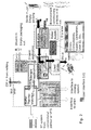
- FIG. 1 A functional diagram of the analyser is shown in figure 1. The main functions are described by:
- FIG 2 a flow diagram of the system in which the analysis instrument is a part, is illustrated. A wet and a dry zone are shown, and an indication of the functional modules is illustrated.
- the functional modules in figure 2 comprises:
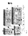
- the configuration diagram in Figure 3 illustrates the elements, which are subjected to functional entities for controlling the instruments.
- the Host element represents the Sample Transport system, which shows up to 32 milking point pipelines connected to a multi valve.
- the milk sample will be transferred through the intake into the mainline in the AI.
- the communication between the Host and the AI can be done by a ALCOM bit protocol via an HSPI interface attached on the Central board.
- the central component comprises a central board which comprises a central module further comprising means for alarm function, means for light function, man machine interface, computing means, control means.
- the dosage component comprises a dosage board which comprises a dosage module further comprising pipes, a drain and diluent.
- the incubation and storage component comprises an Incubation Storage board further comprising an Incubation Module and a Storage module.
- figure 5-17 illustrates an exploded view of the cabinet with the internal mechanical structure and devices as well as the outer design.
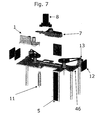
- the mechanical functions are realised in modules that can be assembled and exchanged with a minimum of adjustments. Most of these modules are mounted to a central beam 46, that gives precise tolerances between the modules.
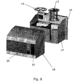
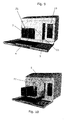
- the operator user interface 19 is shown in figure 9 which also shows the front of the AI with the front door open 20 and the exchangeable parts assembled in their positions.
- Figure 10 shows the same view but with the exchangeable parts partly removed from their assembled position.
- the cabinet can be defined as:
- a central problem in the cabinet design is to prevent humidity and dust from entering the cabinet. This has been solved by closing the outer cabinet and the insulation enclosures as effectively as possible, creating a double enclosure.
- a structure having a main cabinet as structure for insulation enclosures and the mechanical modules and the hardware (HW) is used.
- the internal devices and structures are protected towards the outer environment, by an outer top cover and insulation enclosures, creating a double sealing towards the environment.
- the only openings into the cabinet are preferably the inlet for cartridges, where a reload hatch can be opened, and the consumables room where diluent can be loaded and the stickwaste container removed. These two openings are carefully designed in order to avoid air penetration when closed.
- a front door 31 in the outer cabinet gives the user access to the user interface 19, preferably comprising a keyboard, screen/display, cartridge load 5, stickwaste container 4, diluent container 3, liquid waste funnel 11, filter for milk sample 21 etc.
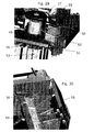
- a beam mounting concept has been designed where the beam is mounted on two linear drawer slides 47 that allow the beam to be drawn out to a service position shown in figure 28.
- the main parts of the external cabinet is a front door 31, a top cover 30, a main cabinet 32, a cooling fin enclosure 34, a window 33, and a mounting frame, see figure 24. All the external parts are preferably made of stainless steel.
- the mounting frame or beam shown in figure 24 preferably comprises a cut out for mounting of a driver module comprising sensors shown in figure 29, a cut out for mounting of a bearing house for both the incubator and storage 37, 39, a cut out for mounting of a stickmover module, a cut out for a dosing needle 41 wherein the cut out preferably comprises a circular area and a slit, wherein the circular area is where the waste funnel, drain preferably is located and the slit is where the dosing needle moves to different positions for dosing a sample on to a test stick.
- the mounting frame preferably comprises a cut out for a hatch.
- the internal parts of the cabinet is the insulation enclosure that consist of the bottom insulation part 29, the top insulation part 10, the consumables room 27, the cooling modules 22, also shown in figure 96 and 97, and the beam mounting system 47.
- the front door 31, figure 21, gives access for the user to refill stick storage, refill diluents and empty the waste container.
- the front door is attached with hinges to the front cover. There are preferably two hinges in the bottom of the door, and preferably two locks at the top of the door.
- the front door is sealed between the top cover with an extruded silicone gasket 35 (preferably Elsteel type).
- the front door preferably has a window 33 that allows the user to see the display, when the door is closed.
- the top cover, figure 22 is hinged in the back/top of the main cabinet, with two adjustable hinges.
- the flange which seals to the main cabinet has an extruded silicone gasket (Elsteel type).
- the profile of the flange ensures a simple protection of the gasket, figure 23.
- the closed top cover is locked with a line of screws at the front/lower edge. The hinges can be adjusted in a way that when the locking screws are tightened the gasket will have an even pressure over the entire gasket surface.
- top cover When the top cover is opened, it will be held in open position with either a gas damper or a simple rod like on an automobile hood. Opening of the top cover gives access to remove the top insulation part.
- the main cabinet holds the insulation enclosure, see figure 22, the top cover and the cooling fin enclosure.
- the main cabinet and the top cover together form the primary sealing against the environment.
- the back of the main cabinet has brackets that mount on the mounting frame..
- Cooling fin enclosure :
- the cooling fin enclosure 34 prevents dust and water from entering the cooling fins 22 and protects the cooling fans and fins.
- the air intake for the fans is preferably provided with a filter mat that will keep the dust out.
- the filter mat can be replaced / cleaned.
- the cooling fin enclosure is sealed against the main cabinet preferably with a rubber gasket, see figure 22 and 97.
- the mounting frame is the interface between the AI and the wall/floor or wherever the AI has to be mounted. A standard range of mounting frames has to be considered.
- the mounting frame is preferably equipped with vibration dampers.
- the insulation Enclosure consists of a top 10 and a bottom 29 insulation part.
- the material is preferably either Expanded polystyrene (EPS) or Polyurethane (PUR).
- EPS Expanded polystyrene
- PUR Polyurethane
- the insulation enclosures has to be either coated or provided with a lining of thermoformed plastic.
- the insulation enclosure preferably has three separate compartments that are sealed from each other.
- the three compartments are the IM compartment 43(Incubator Module), the SM (Storage Module) compartment 44, and the ICM (Integrated Control Module, containing all electronic boards) compartment 45, se figure 25.
- the separation between the IM and SM compartment consist of a wall partly attached to the beam and to the top/bottom insulation parts.
- the top and bottom insulation parts are provided with an aluminium profile on the flange surfaces.
- the aluminium profile has a grove for the silicone gasket.
- the two aluminium profiles are tightened against each other with a number of screws to ensure the sealing of the 3 compartments.
- a dessicant or molecular sieve bag is preferably placed in the ICM compartment. This bag may be replaced at regular intervals.
- the consumables room 27, see figure 28, is preferably made of thermoformed ABS.
- the consumables room is preferably attached to the bottom of the beam, and thus follow the beam when the beam is drawn to service position.
- the openings in the consumable room 27 for the tubes and the sample waste funnel will be kept as sealed as possible, this is to reduce the air exchange when the consumables room is opened for daily operation.
- the beam mounting system 47 consists off two linear slides that holds the beam in position, and allows the beam to be drawn forwards to the service position with improved service access, see figure 28.
- the beam mounting system is attached to the main cabinet with a bracket through the bottom insulation. When the beam is in the service position the storage carrousel is clear from the insulation bottom, and can be dismounted and removed downwards. A locking system will secure that the beam is kept in the right position when in home position.
- the cables from the ICM preferably has to be dismounted and extension cables may be mounted to operate the beam in the service position.
- the cooling modules 22, 150 see figure 96 and 97, is preferably placed at the bottom of the cabinet. This allows the outside part of the cooling modules to be serviced from bottom of the AI when the cooling fin enclosure is removed.
- the fans for the external cooling fins have to be protected against the humidity in the stable environment. This could be either individual fans for each cooling fin, or a common fan with a distribution air pipe to the cooling fins.
- the cabinet shown in figure 5-17, may be defined as:
- Figure 11 and figure 12 illustrates an exploded view of the overall description of the casing.
- the front door 20, the outer front cabinet 18, the inner cabinet 17 and the outer back cabinet 16 can be seen, as well as some of the insulation enclosure.
- Figure 12 shows the same parts but from a different view angle, this time from behind with the outer back cabinet removed so that the cooling ribs on the inner cabinet backside can be seen.
- the cabinet In order to prevent humidity and dust from entering the cabinet and at the same time allowing airpassage when temperatures are changing.
- the cabinet is closed as effectively as possible and pressure release is done through a valve where humidity and dust can be controlled.
- a structure having an inner cabinet as structure for the mechanical modules and the hardware (HW) is used, see figure 5 and 7.
- the internal devices and structures are protected towards the outer environment, by an outer front cabinet shown in figure 8.
- the only openings into the inner cabinet are preferably at the inlet for cartridges 5, where a hatch can be opened.
- the hatch can be a part of the storage/central beam structure, at the stick waste container 4 and at the liquid waste funnel 11 shown in figure 9 and 10.
- the outer back cabinet shown in figure 12 serves to protect the outer cooling fins and a fan shown in figure 12 or 15. Air can flow through this part of the cabinet.
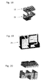
- the insulation enclosures shown in figure 18-20 secure a stable temperature and minimal power consumption for cooling and heating to desired temperatures. They also serve as a moisture barrier together with the outer cabinet.
- a front door gives the user access to the user interface 19, shown in figure 9 and 10 (keyboard, screen, cartridge load, stickwaste container, diluent container, liquid waste funnel, wet system filter). Furthermore the front door also serves as a double protection for the inner cabinet.
- the plate parts of the cabinet are preferably made of stainless steel plates welded together. However other sorts of metals can be used. Other alternative material could e.g. be polymers.
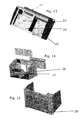
- the inner cabinet shown in figures 8, 13 and 14, is preferably welded of stainless steel plates. It serves as structure for the insulation enclosures, the upper beam, internal and external fans 28, cooling ribs 22 and peltier elements.
- a room in the cabinet is reserved for the diluent- and stickwastecontainer, shown in figure 14. This room also gives access to the liquid waste funnel and the wet system 1 filter 21.
- the conditioning or thermostatation of storage and incubator is done with at least one peltier element for each room, see figure 14.
- a peltier element or thermoelectric heat pump is a solid-state active heat pump which transfers heat from one side of a device to the other.
- the outer cooling ribs are placed in a separate cabinet figure 13-15. They could alternatively be placed inside the inner cabinet. A surface treatment of the outer cooling ribs could be necessary to withstand the environment.
- the peltier elements, the cooling ribs and insulation between the cooling ribs can be assembled as a sandwich, in order to be removable as a whole or partly from the cabinet. Gaskets between the outer cooling ribs and the cabinet secure the tightness of the cabinet.
- the peltier elements are placed in connection with the outer cooling ribs in order to provide a more effective heat transfer from the elements.
- An aluminium bridge can be used to connect the peltier elements and the inner cooling ribs.
- the cooling ribs may be placed vertical in the back of the inner cabinet, see figure 13-15, in order to get a short direct transfer of heat from inside to outside. Additional the vertical orientation secures that eventual condensation can be assembled in the bottom of the cabinet and removed.
- FIG. 13 and 14 shows the passage for used sticks 23, the passage for liquid waste funnel 24, structure for mounting of beam 25, internal fans 26 and room for diluent and stickwaste 27.
- a fan for each room 26 and one or two external fans 28 removes the heat energy from the cooling ribs see figure 14 and 15.
- the fans are preferably constantly running during operation.
- Plates for guiding the heated/cooled air are mounted to the inner cabinet or the insulation. Heat guide elements is a possibility for distributing heat/cold correctly in the rooms.
- the room gives access for removing and cleaning the wet system funnel 11 and the filter 21.
- a structure serves for mounting the central beam to the cabinet. See figure 7, 13 number 25.
- the central HW board in figure 3 and the two RIO (Remote input/output) boards 12, figure 7, may be mounted to the inner cabinet or to the beam.
- a pressure release valve compensating for changing temperatures may preferably be used.
- a connection box is placed on the back or the bottom of the main cabinet.
- the box preferably has connections for milk sample inlet tubes, signal cable, power cable etc.
- Milk sample waste could be connected in the same box or in the bottom of the cabinet. Also the connections for external light and alarm preferably passes this connection box. All connections pass the cabinet in IP65 and airtight cable passage components.
- all cables are sealed in order to avoid air movements between inner cables and outer cable protection.
- the outer front cabinet shown in figure 9-10, has openings for the reload hatch where cartridges are loaded and for the consumables room.
- the display and keyboard are preferably mounted directly to the front plate in order to obtain tightness, see figure 9.
- the outer front cabinet has IP65 tightening against the inner cabinet backplate and tightening against the consumables room and the frame for the reload hatch.
- the outer cabinet can be removed from the inner by releasing locks or nuts in the front plate and pull it towards the operator.
- a sensor checks whether the front cabinet is mounted to the inner cabinet.
- a thin insulation can be applied by gluing it to the inside of the inner cabinet in order to improve the insulation capacity even further.
- the front door in figure 11 preferably has sensors for ensuring that the door is closed, if the front door is not properly shut preferably a light and/or sound signal will alert the operator.
- hinges, lock and handle are mounted outside gaskets.
- the outer back cabinet serves as protection for the outer fan and the cooling ribs, and for mounting the AI on to a wall or another suitable surface.
- the outer back cabinet is shown in figure 17.
- a hole in the outer back cabinet serves as passage for the connection box.
- Gaskets secure tightness to inner cabinet. Openings in the bottom and top of the outer back cabinet secures airflow over the cooling ribs figure 15. Damping elements between the mounting brackets and the outer back cabinet can be used in order to lower the impact of possible mechanical vibrations from the surface on which the AI is mounted to.
- Figure 18-20 shows an embodiment of the different insulation enclosures inside the AI, which are necessary to keep the temperature stable.
- the temperature in the storage should preferably be kept at 20°C+-3°C, and the temperature in the incubator preferably at 25°C+-3°C.
- the humidity in the storage should preferably be below 30%RH. The insulation serves to obtain this.
- EPS Expanded polystyrene
- PUR Polyurethane
- the cabinet will be manufactured by injecting EPS pellets into a mould and applying steam. This will give an insulation house that should be mounted to the inner cabinet.
- PUR could be injected between two shells, the outer shell could be the inner cabinet.
- Obtainable insulation value for EPS is 0.033 W/mK (type F495). This gives insulation thickness of approximately 35 mm for storage.
- Gaskets between the peltier/cooling ribs sandwich and the insulation are preferably used. Also gasket between the reload hatch frame and the insulation.
- the top insulation shown in figure 6 can be lifted to give access to the dry and wet system.
- a gasket between the top insulation and the insulation enclosure is preferably used.
- the top insulation could alternatively be made of two parts allowing separate access to incubator and storage.
- a lock system between the top insulation and the insulation enclosures is preferably used.
- a sensor will detect whether the top insulation is present or if it has been removed. If it has been removed and not put back into place a signal will alert the operator.
- the beam shown in figure 24, serves as structure for mounting storage disc 48, incubator disc 72 and their drives and sensors, stickmover7, wet system 1, optical reader 8 and frame for reload hatch 5.
- the idea with the beam is to mount the elements with precise tolerance demands to a rigid structure as close as possible to their interacting areas.
- the beam is preferably manufactured of stainless steel. However aluminium may also be used.
- the beam is preferably mounted to the cabinet with slides enabling a retraction of the beam from the cabinet.
- the function is to index the incubator and storage turntables in order for both to be positioned correctly, and thereby allowing a stick to be transferred from storage to incubator.
- Both drives are nearly identical, except for the fixture for the sensors.
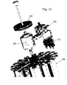
- Figure 29-31 shows a view over a first embodiment of the driving assembly.
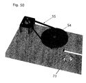
- the drive preferably consists of a 200 increment stepper motor 50 with a press fit pulley, a toothed belt 55 and a bearing assembly comprising shaft with pulley 54, two sealed ball bearings and a machined bearing house 49 secured to the beam.
- the stepper motor and sensors 51 are bolted to a mounting plate that is oriented towards the bearing center by a long hole in the plate and a positioning dowel pin in the beam.
- the mounting of bearings, motor and sensors in one unit enables the SW calibration values for the positioning of the IM/SM discs, to be measured before mounting the drive to the AI beam. This is an advantage for the production and field service.
- the storage/incubator carrousels 48, 72 can be dismantled by loosening the screws mounting the mounting plate to the beam, removing the timing belt 55 and sliding the mounting plate 52 to a bigger radii. By doing this the sensors are free of the carrousel. See figure 30.
- the nut is removed for dismantling of the timing pulley 54, see figure 31.
- the screw head has external thread for the nut. After the nut has been removed the screw can be removed for dismantling of the Storage Module/Incubator Module carrousel.
- the screw and the screw-head have opposite threads.
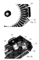
- Figure 42 shows a view over the driving assembly.
- the drive preferably consists of a 200 increment stepper motor 50 with a press fit pulley, a toothed belt 55 and a bearing assembly comprising shaft with pulley, two sealed ball bearings and a machined bearing house secured to the upper beam.
- the stepper motor 50 is bolted to a mounting plate.
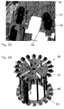
- the storage turntable 48 stores the cartridges, loaded by the operator, and presents them to the stick-mover that sweeps out the DS from the top of the cartridge, see figure 33.
- the storage preferably is a turntable carrousel 48 shown in figure 28.
- each stick cartridge is stored in a keeper 53, which is a box open in the top.
- the keeper is hinged in the bottom so that it can be swung out to present the cartridge to the operator in a horizontal position, illustrated in figure 33.
- the keeper In the upright position the keeper is preferably locked in place by a keeper spring 58, 59 or 64, showing two embodiments of locking arrangement, see figures 32 and 35.
- the keeper is forced outwards by a spring placed at its hinge 61. When the reload hatch is opened the keeper spring is actuated to release the keeper.
- the carrousel is preferably a squirrel cage construction - two discs interconnected by spacer rods 60, illustrated in figure 33.
- the upper disc is equipped with a flange, which is bolted onto the shaft of the drive.
- Upper disc is cut out in a pattern forming places for the cartridges that stick out of the top of the keepers.
- Each cut-out is flanked with a cut-out for the keeper springs that are locking each keeper in the vertical position, see figure 35.
- the bottom disc is ring-shaped and supports the hinges and springs for the keepers.
- the upper disc At each keeper the upper disc have a detection blade providing optional feedback when interacting with photo-interrupters.
- One detection blade is preferably prolonged to provide a "per revolution" sensing.
- a slit is used for the revolution sensing. Sensor and prolonged detection blade could be omitted if the Bar-code reader is integrated in the storage, as it identifies the cartridges.
- the operator closes the reload-hatch that is hinged in the bottom.
- the reload-hatch pushes the keeper that also swings up.
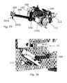
- a depressor arm 116 in the reload hatch driven by a coulisse 117, pushes the cartridge further down into the keeper, against the force of the pusher spring 166 placed in the bottom of the keeper, see figure 100.
- the coulisse 117 is a part that is pushed by the reload hatch, when the reload hatch is closed. Furthermore the coulisse is provided with a track that guides a pin in the depressor, making the depressor rotate, see figure 79.
- the flipper 123 pushes the keeper the rest of the way.
- the flipper is then retracted from the keeper by the retractor arm 122 in the reload hatch. This leaves clearance between the reload-hatch and keeper, approximately 2 ⁇ 1 mm.
- the backside of the cartridge rests against the edge of the cut out in the upper disc - keeping the position tolerances low.
- the AI opens the reload-hatch as it releases a pawl locking the reload-hatch in the closed position.
- the reload-hatch contains a release arm 118 driven by a coulisse 117 that actuates the keeper spring 121, releasing the keeper when the AI opens the reload-hatch, see figure 79 and 90.
- seawater resistant aluminium Preferably made in stainless steel - 3.5 mm thick however also seawater resistant aluminium may be used.
- the discs are preferably manufactured by using laser cutting, but could be stamped at very high volumes.
- the flanges in the functioning models are turned and milled in aluminium. However composite injection moulding could be more profitable for high volume production.
- the flange may be redesign since the drive also can be placed on the upper beam, instead of on a lower base plate
- the spacer rods 60 in the functioning models are turned in aluminium. For higher volume manufacturing they may be turned in glass fibre or reinforced composite.
- All screws can be of the thread forming type, reducing the cost of parts as simple drilled or stamped holes are used.
- the formed thread is the Metric-standard, meaning that standard M-screws can be used in the need of replacement.
- Springs are preferably made of stainless steel.
- the function of the keeper shown in figure 33, 34, 35, 100 is to maintain and position the cartridge in the storage.
- the positioning has to be adjusted to the height of the stick mover.
- the cartridge has to be oriented radially, so that the stick can be guided in a direct and straight line to the incubator.
- the keeper itself has been made as an item in POM.
- the guide pins 164 for the plunger 160 has been mounted by means of circlips.
- a spring loaded bottom stop 163 has been mounted to secure that the cartridge is being guided towards the upper storage disk. This is shown in figure 100.
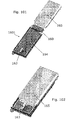
- Internal lead-in in the keeper and the cartridge and external lead-ins in the plunger ensure easy mounting of the cartridge, see figure 100, 101 and 102.
- the cartridge When the cartridge has come approximately 3 ⁇ 4 way down the keeper, it preferably meets a snap-lock, which locks the cartridge in proportion to the keeper, see figure 101.
- a snap-lock In the snap-lock there is approx. 5 mm free space, which is used for the movement when positioning towards the upper storage disc.
- the cartridge is oriented partly by minimal air between the front of the cartridge and the upper storage disc, and partly by two projections on the cartridge, which have minimal air for the periphery of the disk.
- the cartridge is being mounted by means of the reload hatch, it is being pressed down to the bottom stop of the keeper shown in figure 100 and 101.
- the reload hatch depressor loosens up, and the cartridge is being positioned in a given height, which has been adjusted by the tap on the cartridge. In this way, it will have the smallest possible tolerance chain in relation to the stick mover.
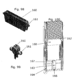
- the plunger 160 shown in figure 98 and 99, exerts an upward force on the sticks in the cartridge to move the stack of sticks up when a stick is removed, presenting next stick for the stick-mover.
- the plunger is forced upwards by two springs.
- the plunger preferably constantly supplies the bottom with an upright force to secure its functions.
- the plunger has preferably been designed in a way that it smoothly fits into the keeper, see figure 98 and 99.
- the only integration for the plunger is the vertical guide way in cartridge 164.
- the plunger is preferably unlocked as much as possible at all other integrations, see figure 100.
- the plunger preferably gets its power from the two springs, which have been placed in the sides and are guided on ⁇ 3 mm stainless stiffeners shown in figure 100 and 101.
- the springs in the Lateral Cartridge (LC) shown in figure 101 are heavier than in the Colorimetric Cartridge (CC) shown in figure 54, due to a larger need for force for increased friction and weight.
- the heavy springs has a built-in length which is slightly larger, and which is possible due to the fact that the 50 sticks in the LC take up less space compared to the 100 sticks in the CC.
- the LC plunger 160 shown in figure 98 has been made by milling POM due to very good friction properties.
- the CC plunger also shown in figure 99 has preferably been injection moulded in POM.
- the chemistry in the sticks is sensitive to humidity (H 2 O) and ammonia (NH 3 ), both represented in a stable environment.
- H 2 O humidity
- NH 3 ammonia
- the preferred levels are that relative humidity is to be kept below 30%, and ammonia is to be kept below 3ppm.
- Stable environment in particular can be up to 100%RH and 20ppm NH 3 at 45°C.
- a 4A molecular sieve see figure 114, with the ability to adsorb both ammonia and water gives the best overall solution, since it retains its ability to adsorb water molecules over a much wider spectrum of temperature than other desiccants.
- the preferred way to gain access to the desiccant is through the reload hatch, and the preferred overall solution is therefore to allocate a place in the storage turntable to a desiccant cartridge.
- a desiccant cartridge would consist of a perforated lateral stick cartridge with an app. 50g. of desiccant in pellet size 1-1.6mm.
- desiccant cartridges are delivered individually in sealed bags. Change of a desiccant cartridge is similar to the change of a lateral cartridge. Airflow through the desiccant is achieved by letting the storage carrousel slowly rotate, when no sticks are required.
- the humidity level is monitored in the AI, and exchange of desiccant will be based upon a time/humidity profile: as the operator is notified about the need to change a lateral or colorimetric cartridge, the AI checks two parameters:
- One set-up is a lateral cartridge with stamped or drilled holes and loaded with desiccant, see figure 114, in a permeable (Gore-Tex) bag.
- the moulded cartridge will be bigger and perforated with small holes. This may at least give 2 benefits:
- Sensor C is used for counting steps from interrupt from sensor to tunnel position. (C may also be used during initialisation. A is preferably only used for the 360° signal, B is preferably only used during power up).
- a second embodiment for obtaining a pr revolution signal is using a hall-effect sensor placed at the periphery of the storage and a magnet placed at the storage disc.
- a third embodiment for obtaining pr revolution signal is using a blade that protrudes further than the rest of the blades on the storage disc and a photo sensor.
- Figure 38 illustrates 360° seen from the bottom of AI.
- FIG 39 illustrates Power up.
- Figure 40 illustrates why use of signal from 3 sensors is preferred:
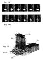
- Figure 59 illustrates the starting position with detection blade behind sensor I.
- sensor I shows 0 and sensor II shows 1.
- Both the Storage Module carousel and Incubator Module carousel is able to rotate.
- Figure 60 illustrates home position where home position preferably is registered by sensor I shows 1, (sensor II shows 1). Stop at the delivery position for Lateral Stick, Colour Stick and waste, is preferably registered by counting the steps from home position or from the position shown in figure 61.
- the Incubator Module carousel may rotate until e.g. a Lateral Stick front passes the tunnel entrance. Preferably this position is identified by counting the number of steps from home position.
- Figure 61 illustrates pawl inside tunnel, sensor I shows 1, sensor II shows 0.
- the Storage Module carousel may rotate.
- Figure 62 illustrates when the pawl is outside tunnel, sensor I shows 0, sensor II shows 0.
- the Storage Module carousel may rotate.
- the position-sensing enables the synchronisation of the virtual position in software (SW) and the physical position of turntable.
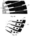
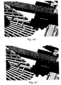
- the turntables are divided into positions, figure 46 and 33, the incubator (figure 45) has stick slots and the storage has cartridge slots (figure 33).
- Each position is provided with a detection blade that interacts with a photo interrupter by interrupting the light beam.
- the flank of any detection blade is used for zero-setting the position counter.
- the flank is received a number of steps before the correct positioning, the so-called offset.
- the offset parameter can, if needed, be adjusted during assembly and test, to take up manufacturing tolerances.
- the power-up and hard-restart strategy states the need of "near right position"-sensing. This is because the start-up sequence of synchronisation does not allow the rotation of turntables before it is ensured that the stick-mover is not engaged with a turntable.
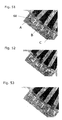
- An additional photo interrupter is used together with the home-flank sensing photo interrupter. Each photo interrupter is positioned at a detection blade, their mutual distance being bigger than the mutual distance between the outer flanks of the two detection blades, see figure 51-53. The condition that both light beams are not interrupted is therefore only at "near right position".
- the denomination "near right position" is used, as the precision of the position is much poorer than when a flank is used.
- the slots of the incubator are genderless/anonymous, see figure 46-47. Any detection blade can be used for home.
- the cartridge positions of the storage turntable are unique, see figure 34-35, since there is colorimetric, lateral flow and desiccant cartridges.
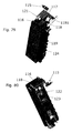
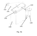
- the reload hatch, figure 79-90 enables the renewal of cartridges by the operator. Together with the storage turntable it presents used cartridges to the operator who will renew the cartridge.
- the reload hatch also comprises sensing means in order to be able to secure that the hatch has been correctly closed and that it is in the closed position.
- the reload hatch is equipped with a lock arrangement that closes the last 5-10 mm of the hatch movement.
- the lock can for example be a pawl driven by a linear stepmotor or a teethrack engaging with a gearwheel on a stepmotor or a dc motor, see figure 83 and 84.
- the reload-hatch is preventing the keeper to swing up during the insertion. This is done with the means of protrusions on the keeper that has entered a hook on the reload hatch flipper during the opening of the reload-hatch.
- the leading in of the cartridge and prevention of accidental twisting of the keeper plunger may be assisted by arms that are swung up on both sides of the top of the keeper during the opening of the reload-hatch.
- the operator closes the reload-hatch that is preferably hinged in the bottom.
- the reload-hatch pushes the keeper that also swings up.
- a depressor arm 116 in the reload hatch driven by a coulissse 117 (see figure 79 and 80), pushes the cartridge further down into the keeper, see figure 100, against the force of the pusher spring 166 placed in the bottom of the keeper.
- This allows a protrusion 65 on the back of the cartridge to pass under the upper disc 56, illustrated in figure 37.
- the depressor arm 116 retracts, cartridge jumps up until the mentioned protrusion rests against the underside of the upper disc - making the chain of tolerances as short as possible, ensuring that each cartridge is leveled in respect to the stick-mover 7 and tunnel 78.
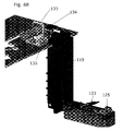
- the flipper 123 When the reload-hatch 124 is almost closed, the flipper 123, see figure 86, pushes the keeper in a swinging motion the rest of the way.
- the flippers motion is initiated by arms 1231 on the bottom of the flipper reaching the reload hatch frame, see figure 82, 85, 86.
- the flipper tilts and the top of the flipper pushes the keeper towards the center of the storage, see figure 86.
- the flipper 123 is then retracted from the keeper by the retractor arm 125 in the reload hatch 124.
- the retractor 125 is equipped with two pins 129. When the pins meet the reload hatch frame 119, the retractor 122 is pushed backwards against its springs 1221. The flipper 123 follow the retractor away from the storage. This leaves clearance between the reload-hatch flipper and keeper 1601, 2 ⁇ 1 mm. The backside of the cartridge rests against the edge of the cut out in the upper disc - keeping the position tolerances low.
- a photointerrupter sense that the reload-hatch is closed and the turntable is allowed to rotate.
- the arm 126 shown in figure 82 is preferably for the purpose of leading wires in a safe way in the embodiment wherein the bar code reader is mounted in the hatch.
- a pawl 136 locks the reload-hatch and a gasket seals against the reload-hatch casing.
- the part of the retractor 125 wherein the pawl 136 interacts is preferably made of metal as shown in figure 90.
- a photointerrupter sense that the reload-hatch is closed and the turntable is allowed to rotate.
- the hatch may comprise a bar code reader 130 for reading bar codes on cartridges.
- the bar code reader is mounted inside the storage in order to protect it from the outer environment.
- the bar code reader may be of laser type or preferably of a CCD type wherein the whole bar code is read and analyses in a computer system.
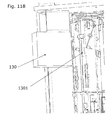
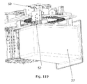
- the barcode may preferably be positioned inside the storage in a position so it is able to read bar codes on cartridges, see figure 117 and 118.
- the cartridge keeper comprises a hole or slit 1301 so that a bar code reader 130 is able to read the bar code on a cartridge when the keeper is rotated in the storage carrousel.
- the AI opens the Reload-hatch as it releases a pawl 136 or other means 1271 locking the reload-hatch in the closed position.
- the reload-hatch contains a release arm 118, fig 79, driven by a coulisse 117 that actuates the keeper spring 121, releasing this from its position in the storage upper disc.
- the pawl is actuated by a dc-motor 133 equipped with a gear wheel. To release the pawl the motor is energized to turn an eccentric pushing the spring loaded pawl. The motor is stopped when it returns to home sensed by a detection blade 115 on the eccentric and a photointerruper.
- the reload-hatch interacts with a spring-loaded arm 118 that actuates the keeper pawl 136, releasing the keeper when the AI opens the hatch.
- the keeper When the keeper is released, it swings out and rests against the partly opened reload-hatch. The operator swings down the hatch, while the keeper follows its motion, until the hatch rests against a stop in a horizontal position.
- the hatch can be equipped with a damper 132 to dampen its opening motion.
- the pawl can be released by sticking a small rod through a hole.
- HW integrates to two photointerrupters and one dc-motor.
- the motor is used unidirectional e.g. no shift of polarity needed.
- One photointerrupter monitors if the reload-hatch is closed.
- the light beam is interrupted when the reload-hatch is closed.
- the storage turntable is allowed to rotate when the reload-hatch is closed.
- the dc-motor 133 is energized.
- the motor is turned off when it returns to home sensed by a detection plate and a photointerrupter. At home the light beam is interrupted by the detection plate.
- a second embodiment of the locking mechanism for the reload hatch comprises a motor, two sensors, a teethrack 134 and a pawl mounted on the coulisse, and a solenoide 135, see figure 87-90.
- the user preferably closes the hatch to a position app. 15 mm before closed position.
- a pawl 136 mounted to the coulisse engages with the hatch.
- sensor 131 is broken and the motor 133 moves the coulisse 117.
- the hatch closes.
- sensor 115 is broken. This activates the solenoide 135 that locks the hatch.
- the solenoide 135 is activated, unlocking the hatch.
- the motor 133 moves the coulisse with the pawl resulting in an opening of the hatch.
- the pawl 136 meets the reload hatch frame 119, it swings away from the hatch.
- the hatch is now free to fall to its fully open position by gravity.
- a damper 132 ensures a controlled motion of the hatch.
- the damper is connected to a gearwheel 132 which is connected to the hatch 124.
- a sensor 131 senses when the hatch is being closed and actuates the motor133 for closing of the hatch.
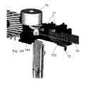
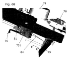
- the stick-mover 7 transfers the stick from the storage to the incubator disc, see figure 54.
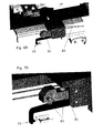
- the stick-mover shown in figure 54, 63-67 and 69-71 consists of:
- the stick-mover is preferably also equipped with a hatch 79 to reduce airflow between incubator and storage chamber.
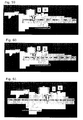
- FIG. 63-67 One embodiment of the function sequence is illustrated in figure 63-67.
- the pawl rests in the reversed position, the Home-position. Thereafter the pawl is lowered.
- the cartridges on the turntable can pass by the tip of the pawl, as it is positioned close to the center of the turntable.
- the motor When the desired cartridge is positioned under the stick-mover, aligned with the stick tunnel, the motor is activated to advance the slide.
- the slide forces the pawl and the pawl lifter to move forward.
- the pawl lifter 81 enters the lower track of the coulisse in the stickmover house.
- the pawl meets the ramp in the cartridge on the top and back of the cartridge.
- the ramp forces the tip of the pawl to flex upwards against the spring force, which eliminates misalignments and levels the tip of the pawl in relation to the stick, see figure 71.
- the tip of the pawl engages the end wall of the stick.
- the end wall of the stick has a shelf-like protrusion matching a cutout in the profile of the tip of the pawl 75, preventing the pawl to slip off the stick.
- the stick is pushed out of the cartridge, passes over the gap between the cartridge and tunnel (2 ⁇ 1 mm) and enters the tunnel 78, assisted by leading-in chambers.
- the storage turntable When stick and pawl have entered the tunnel the storage turntable is allowed to turn to present next cartridge.
- the stick-mover may be stopped in this position to await the indexing of the incubator turntable.
- the slide is advanced further on and the pawl leaves the coulisse.
- the stick passes the gap and into the slot of the incubator and advanced to the intended position.
- the new stick pushes used stick out of the slot.
- the used stick falls into the waste container.
- the slide is reversed and the tip of the pawl slides of the stick.
- the pawl enters the coulisse in its reverse motion and the pawl lifter is being guided into the upper track by the track-changer 84, which is preferably made of a spring wire.
- the pawl is lifted and can now pass over the cartridge, thus allowing the turntable to rotate.
- the slide is returned to home where the pawl is lowered as the upper and lower tracks are connected at this position.
- the motor is turned off and the cycle is complete.
- the motor is driven in 1 ⁇ 2-step mode to enhance the resolution.
- Micro step modes are preferably not used as PM-stepper motors don't perform precisely in these modes.
- the motor is preferably turned off to prevent heat generation.
- the current is preferably reduced to about 50 %, which may reduce the heat generation with up to 75%.
- the synchronism is maintained.
- the stickmover system may comprise a system for securing and checking the transfer of sticks from storage to incubator and the precise positioning of the sticks in the incubator.
- Transfer from storage to incubator An optical reflection sensor, of standard type, placed underneath the passing stick in the stickmover tunnel.
- the stick drawn by the stickmover pawl, passes the sensor, the emitted signal from the sensor will be reflected by the stick and received by the sensor. If the pawl does not draw/carry a stick, no signal will be reflected. Corrective actions can then be made by the SW (E.g.: The error will most likely be caused by a malfunctioning cartridge. A shift to another cartridge containing the same sticktype will result in a successful transfer).
- Three sensors 68 are positioned so that the sensors A and B always see the same signal, see figure 51-53, except when the revolution detection blade passes since the detection blade has a slit, shown in figure 52.
- a second embodiment for obtaining a pr revolution signal is using a hall-effect sensor placed at the periphery of the incubator and a magnet placed at the disc.
- Sensor C is used to count number of steps from interrupt to tunnel positioning. (C is also used for initialisation. A is preferably only used for giving a 360° signal.)
- the main mechanical part is an incubator disc 72 comprising a number of slots.
- the preferred embodiment of an incubator disc is shown in figure 47.
- the incubator disc is necessary for positioning, keeping and guiding the sticks in place during the loading, dosing, incubation, reading and removal steps of the analysis process.
- the number of slots is preferably 45, but this number is governed by the incubation time and the required throughput of sticks. These slots may be divided into the different sectors as described below:
- Position of stick in incubator Two or more reflective sensors above or under the incubator disc, will receive reflected signals if the sticks are positioned correctly. This can be obtained by utilising the pattern of free space and reflective and non-reflective materials in the stick, that is established by the stick and around the stick. If the stick is not positioned correctly it will not be used for analysis, and another stick can be transferred for this analysis.
- the incubator disc may be made of 3 mm stainless steel.
- the manufacturing of the disc can be done by a combination of laser cutting and punching.
- the disc has preferably 45 places, which can be used for both lateral and colorimetric sticks.
- the upper side of the stick meets the bottom of the incubator disc.
- the upper side of the stick meets a surface 71 in the slot. This has the advantage that the stick will not adhere to the incubator carrousel when pushed into the free fall into the waste container.
- the incubator slot has lead-in 70 to obtain tolerances, see figure 43-45.
- the slot also functions so as to guide the wings of the sticks when the sticks are transferred onto the slot.
- the slot has been supplied with a built-in lock to maintain the stick, when the disc is rotating or the apparatus is influenced by external conditions.
- the lock makes sure that the stick is positioned precisely against the disc, when loading or unloading is taking place.
- the stick should preferably be positioned in substantially vertical position in order to facilitate reading the result developed on the stick.
- the incubator slot may be fixed to the disc 72, shown in figure 46, by means of thread shaping screws. Furthermore, in a second embodiment, the incubator slot has detection blades for detection of position. An incubator slot has two detection blades, where the other one can be used for one per revolution sensor.
- FIG. 49 A preferred embodiment for fastening an incubator slot is shown in fig 49 wherein the small towers 69 is heated on the slots, melting the plastic, and in this way locking the slots to the carrousel disc, see figure 49.
- Disc 3 mm stainless AISI 304. Manufactured by laser cutting and stamping. Weight: 640 g. Slot: Injection moulded in POM. Volume of slot: 550 mm 3 Weight: 0,77 g.
- a first embodiment of the dosage flow system is illustrated in figure 72, and preferably comprises a dosage unit, dosage pumps 95, 96 apportioning different volumes, a drain funnel, a valve and pipes.
- a second embodiment of the Dosage flow system is illustrated in figure 73, and preferably comprises a dosing head 105, dosage pumps 95, 96, a tube pump, a bubble detector, a drain, a multivalve guiding the samples from the milking points to the analyser instrument, valves and pipes.
- the multivalve and the tube pump can be part of the analyser or part of an external system.
- the milk sample is apportioned from the sample transport system to the main line, preferably by a pump placed in the sample transport system.
- the sample is pumped to the mainline drain, in order to clean the mainline for the previous sample.
- the valve is switched to the pipe going to the dosage unit.
- the dosage line is flushed with the sample, with the dosage needle 1041 placed above the drain funnel.
- the dosage head 105 is then moved to the narrow slit in the drain funnel, the position shown in fig 73.
- the diluent line dosage pump (shown below the sample dosage pump on fig 72) is activated. This flushes diluent out in the drain funnel slit, washing the outside of the dosage needle.
- the dosage unit is slowly moved out of the slit. The slow movement ensures that all the diluent is drawn off the needles.
- the dosage unit can now be moved to the dosage position above the stick.
- the sample dosage pump is now activated. Diluent pushes the milk sample
- Figure 74 shows the dosing of milk onto a test stick.
- the milk is applied from approximately 1-3 mm height by pushing the sample with the dosage pump.
- the dosing needle is lowered in order to contact the test stick. By doing this, the droplet is drawn of the needle. In this way the needed precision of the sample volume applied to the stick is obtained.
- the pump/valve arrangement is shown.
- the valve and the pump is mounted on a manifold which contains all connections.
- This manifold is preferably designed without dead volume and easy to clean as it preferably will be cleaned every time the tubes are exchanged (every 6 months).
- the two dosage pumps 95, 96 are preferably precision solenoid membrane types.
- the valve 99 is preferably a 3/2 rocker solenoid valve with minimized dead volume.
- the tubes 97 preferably comprise tubes for inlet and outlet of diluent as well as a tube for dosing.
- the tubes 98 preferably comprises tubes for main line in and main line to drain also shown in figure 72.
- Figure 77 shows a part of the wet system comprising a dosage head 105 comprising holes for mounting of temperature sensor, a heater in form of a resistance, a hole for diluent to the diluent needle and a hole for the sample to the dosage needle.
- the wet system comprises a dosage needle 1041, comprising a cuper cap for warming the sample to body temperature, a diluent needle 1042, a mounting frame preferably fastened to the beam 46, a sensor 108 for sensing preferably a home position, a sensor for sensing a tilting position, a support bar 1101 for linear movement of the slide 110, a stepper motor for 111 for movement of the slide and thus the dosing head, a stepper motor 112 for performing the tilting movement of the arm 106 and dosage head 105 illustrated in figure 74.
- a dosage needle 1041 comprising a cuper cap for warming the sample to body temperature, a diluent needle 1042, a mounting frame preferably fastened to the beam 46, a sensor 108 for sensing preferably a home position, a sensor for sensing a tilting position, a support bar 1101 for linear movement of the slide 110, a stepper motor for 111 for movement of the slide and thus the dosing head, a step
- the two main types of sticks, colorimetric 250 and lateral 251, shown in figure 46, are placed in the incubator disc in positions where reading with the optical reader is done at the same radii. Because of this, dosage has to be done at two different radii. Additionally the dosage has to move to two positions in the drain funnel. The movement between these four positions is obtained with a spindle.
- FIG 78 it is shown how the spindle arrangement with the dosage head 105 may be mounted to the beam above the incubator disc and the drain funnel.
- the dosage head 105 is preferably made so that the needles can be removed for cleaning through the drain funnel fixture, from within the consumable room 27, see figure 119 and 120. This will make cleaning and inspection easy and open for the possibility of plugging in a special dosage metering tool.
- the dosage heating and temperature feedback is done by power resistant and a NTC resistant that are glued in the dosage head. If possible these elements are to be mounted on a small PC board and screwed on the dosage head. This is to simplify assembly and service.
- the diluent container is preferably to be kept on a ramp 102 in the consumables room, preferably with a low level switch that will signal when the diluent level is below a defined level, see figure 76.
- This level should preferably be defined as a little more than is needed for a full milking session.
- the software should keep count on the amount pumped.
- the diluent container is hinged in one end 1000 and resting on a chute or plate 102 so that when the consumable room 27 is opened and the beam is moved to an opened position the chute is moved to a horizontal position making it easier for a user to access the diluent container and replace it with a new.
- the diluent container 101 is a bag made of plastic or rubber or any other material useful for the purpose.
- the diluent container may preferably comprise a protrusion 103, membrane or the alike for penetration of a needle so that diluent may be pumped or sucked into the analysis apparatus.
- the needle is preferably a standard syringe tip with luer connection, a suitable standard spike may also be used due to lower cost and convenience for the user.
- the optical reader module 8 is a part of the MERKUR Analysis Instrument. It is an integrated part of the incubator module with the purpose of "reading" the degree of chemical reaction found on individual dry-sticks after milk has been applied.
- the measurement object field which is identical to the reaction field 170, is illuminated with either green or red light, and the amount of reflected light is measured with a calibrated sensor.
- the average of reflected light from a defined part of the object field 171 is used as a measure for the amount of "tracer", see figure 103.
- Type 2 lateral flow test line
- the measurement object field 171 which includes the background substrate and the reaction line 175, see figure 104, is illuminated with preferably either green or red light, and the amount of reflected light is measured with a calibrated sensor.
- the strength of the reaction line is used as a measure for the amount of "tracer".
- the ORM is a self-controlled unit capable of capturing an image of a view field 178 and to perform a calculation of reflected light in a defined object field 171 according to the type of object presented.
- the ORM context diagram can be seen in figure 105.
- the ORM may be used for "reading” or after power-up the embedded controller.
- the AI 177 may send an initialisation string in order to set-up instrument dependant parameters (E.g. internal grey scale offset).
- the ORM 176 will respond with a state message.
- the ORM is calibrated independent of the AI embedded controller.
- the AI embedded controller may request reading of an object after the object has been brought to a fixed position in the view field 178.
- the request preferably include object type and illumination wavelength.
- the ORM will return the calculated values if the image processing software recognises the object as one of the specified type. If not, the ORM preferably will return a result error message. The ORM will be ready for another reading immediately after returning the latest result.
- the view and object fields are illustrated in the figure 106, as well as in figure 107.
- Design item Design decision Functions Type 1 and 2 reaction reading. Throughput/capacity Read ratio preferably better than 2 seconds.
- MORM020 Image sensor 173 National Semiconductors LM9617 Black and white Embedded processor National Semiconductors LM9504 Image processor
- the housing of the ORM is designed to fit into the physical frames dictated by the incubator module.
- Figure 108 and 109 shows the side and end view of an embodiment of the ORM house.
- Figure 110 shows PCB layout component side
- the optical design is illustrated in figure 111 as well. It is governed by the fact that the view area of 8*8 or 8*12 mm preferably is down-sized to a part of the sensor area of 4*5 mm of the imager sensor chip 173 from National semiconductors.
- the image sensor 173 is preferably a standard VGA colour chip with the dimensions 3,66*4,86 mm and a resolution of 480*640 pixels. Using a square of 320*320 or 320*466 pixels gives image size of 2,4*2,4 or 2,4*3,5 mm on the chip surface, which again gives a magnification factor:
- the lens tube preferably comprises a lens 174.
- the housing preferably comprises screening walls 178, and a membrane 177 for closing of the housing.
- the illumination system of the ORM consist of the LED's 172 and a set of reflectors 179 integrated in the ORM housing.
- the light from the LED's is pointed at the reflectors and reflects as diffuse light on the object area, see figure 113.
- the light intensity is preferably controlled by a internal grey reference reading.
- the illumination has been placed in the lens fixture close to the PC board in order to bring it as far as possible away from the object area and thus ensuring the least possible variance in reflected light if the object is slightly out of focus.
- it is preferably not necessary to control the light intensity.
- the controller board is preferably equipped with Flash memory, which holds
- the function of the stick waste is to receive the used sticks pushed out of the incubator by the stickmover.
- the system has a funnel leading to a container.
- the funnel has a built in hatch 141 that closes towards the used sticks.
- the hatch is moved by a DC gear motor 144, see figure 91, 92, 94 and 95.
- the function of the detection device serves several purposes, firstly it provides detection of full waste container, in case it is not completely emptied by the operator, secondly the device is able to dissolve an obstruction in the chute, and the device can also function as an airlock between incubator and the surrounding environment.
- the design intent which is illustrated in figure 91, is to let a hatch cover 141, driven by a small DC gear motor 144 perform a sweeping motion across the gap between chute and waste container 140, every time a stick is transferred from storage to incubator.
- the shaft of the gear motor has a crankshaft connected to a pretensioned spring 143. As the shaft only rotates in one direction, the spring will pull the hatch cover 141 positively to a stop when closing, and push the hatch cover when opening motion is called upon.
- the waste container 140 is preferably mounted in the apparatus by inserting it into a docking station 146.
- a plate 147 may be used for mounting.
- the sticks are preferably kept in storage at 20°C, before they are transferred to the incubator, where they preferably achieve a temperature of at least 30°C, before dosing in order to avoid milk fat depositing on the sample. Since the temperature inside the incubator module preferably is 37°C, one way of achieving the heat-up of sticks, would simply be to let them cure from slot number 1(transfer slot) to the dosing slot. Tests have shown that for a colorimetric stick, it takes ⁇ 40s to rise from 20°C to 30°C by natural heat convection, while it only takes ⁇ 15s when forced convection is applied by means of a small fan 73. If natural convection was to be used, it would require 6 spaces, and dosing would take place at slot number 7.
- the stick frames shown in figure 46 and 70 provide handle-ability to the chemistry pad.
- the path of handling from production to waste is:
- the chemistry has two formats, lateral 251 flow and colorimetric 250:
- the overall height, 2.5 mm, of both frames is determined by the LS, as the chemistry is thicker - at this point of time 1.6 mm.
- the floor of the LS-frame is 0.6 mm thick, leaving a clearance of 0.3 mm from the top of the frame to the chemistry.
- the stack-height of the LS is the full 2.5 mm.
- the stack-height of the CS is reduced to 1.4 mm, by reducing the thickness of the frame body, utilizing the thinner chemistry.
- the wings of the frame allow the DS to be guided in the stick-mover tunnel and incubator slot.
- the guide ways are formed like [ ]-tracks, 1 mm high and 0.8 mm wide.
- the stick-mover pawl pushes the stick on its end-wall.
- the end-wall has a shelf-like protrusion that engages with the stick-mover pawl, preventing it from sliding of and over.
- the wings are extended beyond the end walls of the frame. This makes room for the stick mover pawl when the next DS jumps up in the cartridge when a stick is swept out.
- the LC lateral cartridge
- the CC colorimetric cartridge
- a cartridge consists of two injection-moulded shells, which have been ultrasonic welded together.
- the shells are made of impact modified PS, which has been chosen due to the favourable price and the mechanical qualities desired, both regarding strength/stiffness and welding.
- the bottoms such as the one shown in figure 100, have been used.
- the item has been made of bent sheet metal, so that its shoulders are flexible and act as a lock.
- the lock runs against four internal one-way stairs in the cartridge.
- Items for function models have been made of stainless steel by way of laser cutting and bending.
- the sticks are mounted in the cartridge in the following way:
- cartridges To get the sticks to the top of the cartridge, the cartridge is held, while the auxiliary plate of the fixture is being pushed upwards. To secure that the stack of sticks are kept in place, cartridges may be loaded and unloaded in a keeper.
Landscapes
- Health & Medical Sciences (AREA)
- Chemical & Material Sciences (AREA)
- General Health & Medical Sciences (AREA)
- Life Sciences & Earth Sciences (AREA)
- Analytical Chemistry (AREA)
- Physics & Mathematics (AREA)
- Biochemistry (AREA)
- General Physics & Mathematics (AREA)
- Immunology (AREA)
- Pathology (AREA)
- Food Science & Technology (AREA)
- Engineering & Computer Science (AREA)
- Chemical Kinetics & Catalysis (AREA)
- Clinical Laboratory Science (AREA)
- Medicinal Chemistry (AREA)
- Hematology (AREA)
- Apparatus Associated With Microorganisms And Enzymes (AREA)
- Automatic Analysis And Handling Materials Therefor (AREA)
- Investigating Or Analysing Biological Materials (AREA)
- Sampling And Sample Adjustment (AREA)
- Investigating Or Analysing Materials By Optical Means (AREA)
Applications Claiming Priority (3)
| Application Number | Priority Date | Filing Date | Title |
|---|---|---|---|
| DKPA200300751 | 2003-05-19 | ||
| DKPA200400358 | 2004-03-03 | ||
| EP04733767A EP1627232B1 (de) | 2003-05-19 | 2004-05-19 | Vorrichtung zur analyse von körperflüssigkeit |
Related Parent Applications (1)
| Application Number | Title | Priority Date | Filing Date |
|---|---|---|---|
| EP04733767A Division EP1627232B1 (de) | 2003-05-19 | 2004-05-19 | Vorrichtung zur analyse von körperflüssigkeit |
Publications (1)
| Publication Number | Publication Date |
|---|---|
| EP1892043A2 true EP1892043A2 (de) | 2008-02-27 |
Family
ID=33454267
Family Applications (2)
| Application Number | Title | Priority Date | Filing Date |
|---|---|---|---|
| EP07122841A Withdrawn EP1892043A2 (de) | 2003-05-19 | 2004-05-19 | Vorrichtung zur analyse von körperflüssigkeit |
| EP04733767A Expired - Lifetime EP1627232B1 (de) | 2003-05-19 | 2004-05-19 | Vorrichtung zur analyse von körperflüssigkeit |
Family Applications After (1)
| Application Number | Title | Priority Date | Filing Date |
|---|---|---|---|
| EP04733767A Expired - Lifetime EP1627232B1 (de) | 2003-05-19 | 2004-05-19 | Vorrichtung zur analyse von körperflüssigkeit |
Country Status (9)
| Country | Link |
|---|---|
| EP (2) | EP1892043A2 (de) |
| AT (1) | ATE381020T1 (de) |
| AU (1) | AU2004239381B2 (de) |
| CA (1) | CA2526391C (de) |
| DE (1) | DE602004010649T2 (de) |
| DK (1) | DK1627232T3 (de) |
| ES (1) | ES2298756T3 (de) |
| NZ (1) | NZ544114A (de) |
| WO (1) | WO2004102183A2 (de) |
Cited By (1)
| Publication number | Priority date | Publication date | Assignee | Title |
|---|---|---|---|---|
| WO2020095131A1 (en) * | 2018-11-07 | 2020-05-14 | Foss Analytical A/S | Milk analyser for classifying milk |
Families Citing this family (5)
| Publication number | Priority date | Publication date | Assignee | Title |
|---|---|---|---|---|
| ATE487145T1 (de) * | 2005-07-26 | 2010-11-15 | Raudszus Electronic Gmbh | Verfahren und vorrichtung zur probennahme und unmittelbaren analyse fliessfähiger sammelgutmengen, insbesondere von milchlieferungen |
| EP2171431B1 (de) | 2007-06-28 | 2017-09-13 | Koninklijke Philips N.V. | Mikroelektronische sensorvorrichtung für optische untersuchungen auf einer angefeuchteten oberfläche |
| EP3827258B1 (de) | 2018-07-24 | 2024-08-14 | S.C.R. (Engineers) Limited | System und verfahren zur fluidprobenabgabe |
| CN110940720B (zh) * | 2019-11-25 | 2020-08-25 | 徐州医科大学 | 一种自动按压的醋酸纤维素薄膜点样器 |
| CN120593619B (zh) * | 2025-06-24 | 2026-05-01 | 陕西中天火箭技术股份有限公司 | 一种非接触式可同时兼容棒料及筒件检测装置 |
Family Cites Families (2)
| Publication number | Priority date | Publication date | Assignee | Title |
|---|---|---|---|---|
| US5534224A (en) * | 1993-07-16 | 1996-07-09 | Fuji Photo Film Co., Ltd. | Chemical analysis film cartridge |
| DE19919305A1 (de) * | 1999-04-28 | 2000-11-02 | Roche Diagnostics Gmbh | Verfahren und Vorrichtung zum Flüssigkeitstransfer mit einem Analysegerät |
-
2004
- 2004-05-19 EP EP07122841A patent/EP1892043A2/de not_active Withdrawn
- 2004-05-19 CA CA2526391A patent/CA2526391C/en not_active Expired - Fee Related
- 2004-05-19 NZ NZ544114A patent/NZ544114A/en not_active IP Right Cessation
- 2004-05-19 AU AU2004239381A patent/AU2004239381B2/en not_active Ceased
- 2004-05-19 EP EP04733767A patent/EP1627232B1/de not_active Expired - Lifetime
- 2004-05-19 ES ES04733767T patent/ES2298756T3/es not_active Expired - Lifetime
- 2004-05-19 DK DK04733767T patent/DK1627232T3/da active
- 2004-05-19 AT AT04733767T patent/ATE381020T1/de not_active IP Right Cessation
- 2004-05-19 DE DE602004010649T patent/DE602004010649T2/de not_active Expired - Lifetime
- 2004-05-19 WO PCT/DK2004/000355 patent/WO2004102183A2/en not_active Ceased
Cited By (6)
| Publication number | Priority date | Publication date | Assignee | Title |
|---|---|---|---|---|
| WO2020095131A1 (en) * | 2018-11-07 | 2020-05-14 | Foss Analytical A/S | Milk analyser for classifying milk |
| CN113228049A (zh) * | 2018-11-07 | 2021-08-06 | 福斯分析仪器公司 | 用于将奶分类的奶分析仪 |
| US20220051389A1 (en) * | 2018-11-07 | 2022-02-17 | Foss Analytical A/S | Milk analyser for classifying milk |
| US11721094B2 (en) * | 2018-11-07 | 2023-08-08 | Foss Analytical A/S | Milk analyser for classifying milk |
| CN113228049B (zh) * | 2018-11-07 | 2024-02-02 | 福斯分析仪器公司 | 用于将奶分类的奶分析仪 |
| AU2019377262B2 (en) * | 2018-11-07 | 2024-05-02 | Foss Analytical A/S | Milk analyser for classifying milk |
Also Published As
| Publication number | Publication date |
|---|---|
| AU2004239381B2 (en) | 2009-04-23 |
| AU2004239381A1 (en) | 2004-11-25 |
| DK1627232T3 (da) | 2008-03-10 |
| DE602004010649T2 (de) | 2008-12-11 |
| EP1627232A2 (de) | 2006-02-22 |
| CA2526391A1 (en) | 2004-11-25 |
| ATE381020T1 (de) | 2007-12-15 |
| EP1627232B1 (de) | 2007-12-12 |
| NZ544114A (en) | 2007-12-21 |
| WO2004102183A2 (en) | 2004-11-25 |
| WO2004102183A3 (en) | 2005-05-06 |
| CA2526391C (en) | 2010-04-13 |
| DE602004010649D1 (de) | 2008-01-24 |
| ES2298756T3 (es) | 2008-05-16 |
Similar Documents
| Publication | Publication Date | Title |
|---|---|---|
| US8262991B2 (en) | Apparatus for analysing fluid taken from a body | |
| US10155225B2 (en) | Automated reagent manager of a diagnostic analyzer system | |
| CN112362884B (zh) | 一种全自动光激化学发光检测仪 | |
| US9797916B2 (en) | Chemical analyzer | |
| US20110223064A1 (en) | Sample analyzer | |
| JP2019521359A (ja) | 自動臨床分析器システム及び方法 | |
| JP4288283B2 (ja) | 試験試料担体用運搬システム | |
| CA2054454A1 (en) | Apparatus for shuttling a test element from a discharge path to a wash station | |
| JPH06324056A (ja) | 患者の液体サンプル用の分析器 | |
| AU2004239381B2 (en) | An apparatus for analysing fluid taken from a body | |
| CN112230009A (zh) | 样本传输检测方法 | |
| CN110160957A (zh) | 试剂盘模块及光激化学发光检测仪 | |
| CN113341129A (zh) | 一种荧光免疫分析装置及控制方法 | |
| JP4632670B2 (ja) | 濁度検出用光学装置及びそれを用いた濁度検出装置 | |
| CN112513644B (zh) | 自动分析装置 | |
| EP2116849A2 (de) | Streifenversorgungsvorrichtung | |
| CN218766957U (zh) | 用于分子诊断设备的配平卡 | |
| JP2010101910A (ja) | 試薬吸引方法 | |
| JP5216820B2 (ja) | 分注装置および核酸分析装置 | |
| EP4498090A1 (de) | Molekulare diagnosevorrichtung und testkartenfördersitz für molekulare diagnosevorrichtung | |
| JP6850654B2 (ja) | 閉栓装置及びシステム | |
| JP5452526B2 (ja) | 自動分析装置 | |
| JP7670858B2 (ja) | 試薬保管庫、および自動分析装置 | |
| CN117184620A (zh) | 样本测定装置以及样本测定方法 | |
| CN116699158A (zh) | 分子诊断设备 |
Legal Events
| Date | Code | Title | Description |
|---|---|---|---|
| PUAI | Public reference made under article 153(3) epc to a published international application that has entered the european phase |
Free format text: ORIGINAL CODE: 0009012 |
|
| AC | Divisional application: reference to earlier application |
Ref document number: 1627232 Country of ref document: EP Kind code of ref document: P |
|
| AK | Designated contracting states |
Kind code of ref document: A2 Designated state(s): AT BE BG CH CY CZ DE DK EE ES FI FR GB GR HU IE IS IT LI LT LU LV MC MT NL PL PT RO SE SI SK TR |
|
| AX | Request for extension of the european patent |
Extension state: AL BA HR MK YU |
|
| RIN1 | Information on inventor provided before grant (corrected) |
Inventor name: SONNENBORG, FREDERIK NIKOLAJ SVAERKE Inventor name: GUDMUNDSSON, KRISTJAN FREYR Inventor name: CHRISTIANSEN, PETER Inventor name: CARLSEN, THOMAS NIKOLAI |
|
| STAA | Information on the status of an ep patent application or granted ep patent |
Free format text: STATUS: THE APPLICATION IS DEEMED TO BE WITHDRAWN |
|
| 18D | Application deemed to be withdrawn |
Effective date: 20111201 |