EP1892053A2 - Dispositif d'alignement et de positionnement d'objets - Google Patents
Dispositif d'alignement et de positionnement d'objets Download PDFInfo
- Publication number
- EP1892053A2 EP1892053A2 EP07016668A EP07016668A EP1892053A2 EP 1892053 A2 EP1892053 A2 EP 1892053A2 EP 07016668 A EP07016668 A EP 07016668A EP 07016668 A EP07016668 A EP 07016668A EP 1892053 A2 EP1892053 A2 EP 1892053A2
- Authority
- EP
- European Patent Office
- Prior art keywords
- line
- holder
- lasers
- housing
- laser
- Prior art date
- Legal status (The legal status is an assumption and is not a legal conclusion. Google has not performed a legal analysis and makes no representation as to the accuracy of the status listed.)
- Withdrawn
Links
- 230000003287 optical effect Effects 0.000 claims description 13
- 238000001816 cooling Methods 0.000 claims 2
- 230000001681 protective effect Effects 0.000 description 2
- 238000005096 rolling process Methods 0.000 description 2
- 239000000725 suspension Substances 0.000 description 2
- 238000010276 construction Methods 0.000 description 1
- 230000007423 decrease Effects 0.000 description 1
- 230000001419 dependent effect Effects 0.000 description 1
- 238000000151 deposition Methods 0.000 description 1
- 230000000694 effects Effects 0.000 description 1
- 239000003550 marker Substances 0.000 description 1
- 230000005855 radiation Effects 0.000 description 1
- 239000000758 substrate Substances 0.000 description 1
Images


Classifications
-
- B—PERFORMING OPERATIONS; TRANSPORTING
- B23—MACHINE TOOLS; METAL-WORKING NOT OTHERWISE PROVIDED FOR
- B23D—PLANING; SLOTTING; SHEARING; BROACHING; SAWING; FILING; SCRAPING; LIKE OPERATIONS FOR WORKING METAL BY REMOVING MATERIAL, NOT OTHERWISE PROVIDED FOR
- B23D33/00—Accessories for shearing machines or shearing devices
- B23D33/12—Equipment for indicating where to cut
-
- G—PHYSICS
- G01—MEASURING; TESTING
- G01C—MEASURING DISTANCES, LEVELS OR BEARINGS; SURVEYING; NAVIGATION; GYROSCOPIC INSTRUMENTS; PHOTOGRAMMETRY OR VIDEOGRAMMETRY
- G01C15/00—Surveying instruments or accessories not provided for in groups G01C1/00 - G01C13/00
- G01C15/002—Active optical surveying means
- G01C15/004—Reference lines, planes or sectors
-
- G—PHYSICS
- G01—MEASURING; TESTING
- G01C—MEASURING DISTANCES, LEVELS OR BEARINGS; SURVEYING; NAVIGATION; GYROSCOPIC INSTRUMENTS; PHOTOGRAMMETRY OR VIDEOGRAMMETRY
- G01C15/00—Surveying instruments or accessories not provided for in groups G01C1/00 - G01C13/00
- G01C15/12—Instruments for setting out fixed angles, e.g. right angles
Definitions
- the present invention relates to a device for aligning and positioning of objects, in particular sheets for a blank.
- the invention has for its object to provide a device for aligning and positioning of objects, which avoids the above disadvantages and in particular is also able to produce with simple means a highly visible marking line over several meters away.
- the device according to the invention for aligning and positioning objects has a holder and at least two lasers.
- the lasers are detachably connected to the holder.
- Each of the lasers is with each provided a line optics, which generates a light plane and has a main emission. In the main emission direction within the light plane, the laser light with the greatest intensity is emitted.
- the line effect causes a light plane delimited by two marginal rays to be emitted which has a greater intensity around the main emission direction than in the marginal regions.
- the lasers are fixed to the support such that the light planes collapse and the main radiation directions are different from each other while enclosing an angle.
- the laser are held relative to each other such that a common light plane is formed with several Hauptabstrahlraumen. If such a light plane is directed onto an object for marking purposes, a laser line is formed along the section of the light plane with the surface of the object.
- the intensity of the laser line has a particularly high intensity or brightness in the region of the main emission direction. It is important in the construction according to the invention that several lasers project the desired marking line in sections onto the object, so that a plurality of lasers with lower powers can be used.
- the use of a very powerful laser which is able to project a highly visible line over the entire section to be marked, has a significantly higher performance and thus a higher safety class than the inventively provided lasers, each only a portion of the Project the marker line at the object.
- the lasers can be arranged in this case in order to produce an overall continuous marking line. But it is also possible to further space the laser, so that an interrupted marking line is formed.
- each of the line optics is set at a distance to which the laser light is focused. Depending on the distance of the mounting location of the device relative to the object to be marked, the distances to which the line optics are focused are different.
- the focal distance of each line optic corresponds approximately to the length of the main emission direction between the laser and the object to be marked.
- two line optics are provided for the laser, which differ in their opening angle of the light plane.
- Aperture angle is that angle which extends between the two outer marginal rays of the light plane.
- a first line optical system is provided whose opening angle in the light plane is smaller than the opening angle of the second line optical system.
- the opening angle of the first line optical system is preferably between 10 ° and 50 °. Particularly preferably, an opening angle between 10 ° and 30 ° is provided.
- the opening angle of the second line optical system is greater and lies in a range between 50 ° and 80 °.
- an angular range of 50 ° to 70 ° is provided here.
- the first line optic When the line optics are assigned to the lasers, it is provided that the first line optic generates the light plane further to the front. With reference to the impact points of the light planes in the main emission direction, this means that the point of impact of the first laser with the smaller aperture angle is closer to the device than the impact point of the second laser.
- FIG. 2 shows a first line laser 10 which is arranged above a second line laser 12.
- Each of the line laser is substantially rod-shaped with a cylindrical aperture 14, 16, the art a cuff is placed on the laser body 18, 20.
- the laser body 18, 20 is located in a cylindrical housing which is held in a holding device 22.
- the holding device 22 consists of a first holding portion 24 and a second holding portion 26, each having a cylindrical receptacle for the laser body 18, 20 have.
- the cylindrical receptacle is provided in each holding section 24, 26 with a slot 28 and is clamped on the laser body 18 via fixing screws 30 which project through the slot 28.
- the holding portions 24, 26 are connected to each other via a pair of screws 32.
- the cylindrical holding portions are inclined at an angle of 10 to 25 degrees, preferably 15 to 20 degrees from each other.
- the inclination angle between the cylinder axis of the first cylindrical receptacle and the cylinder axis of the second cylindrical receptacle is 17 degrees. This angle corresponds to the angle ⁇ , which include the main emission directions with each other.
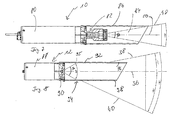
- FIG. 3 shows in a schematic view from the side a light plane 34 of the upper laser 10.
- the light plane has two lateral boundary beams 38 and 40 and one main emission direction 36.
- the brightness is the projected line is the largest.
- the marginal rays 38 and 40 the brightness decreases.
- the lower laser 12 generates a light plane 44, whose marginal rays 46, 48 are also drawn.
- the rear edge beam 46 is offset by a distance A from the suspension point of the laser.
- the rear edge beam 48 hits in the illustrated embodiment in front of the rear edge beam of the upper Lasers on. This leads to a broken projection of the line on the ground.
- an arrangement is also possible in which the rear edge beam 48 strikes the ground farther away from the lasers than the edge beam 40.
- the main emission direction 50 of the lower laser strikes the ground in region 52.
- the line optics of the lasers 10 and 12 are formed such that the upper laser 10 is focused approximately at the point 42, while the lower laser 12 is approximately focused at the point 52.
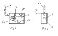
- a holding device 54 is provided, which is releasably attached to a crossbar 56.
- the crossbar 56 is, for example, a rod fixedly provided in the hall of the rolling mill.
- the fastening device 54 has a first holding portion 58, which is fastened via clamping screws 60 to the crossbar 56.
- the first holding portion can in this case both in the longitudinal direction of the cross bar 56 shifted as well as rotated along derem circumference.
- the second portion of the fastener 60 also has a cylindrical receptacle 62 for the body of the first laser 18.
- a protective housing 64 may be provided.
- the protective housing shown in Fig. 5 and 6 has a substantially cuboidal structure, with a lid 66 which can be removed from a housing body.
- the laser 10 and 12 and the holder 54 are arranged.
- a Opening 68 Through which, for example, cables can be guided into the housing interior.
- a temperature sensor 70 is provided in the housing, which measures the air temperature in the housing and activates a so-called Air Gun.
- the air gun sits in a tubular extension 72 which is connected to the housing body and is operated with compressed air, wherein it operates on the vortex tube principle. It is also conceivable to blow fresh air from the environment into the housing interior via a fan in order to cool the lasers.
- the housing 64 may be either connected to the bracket 54 or attached separately to the cross bar 56.
- FIG. 7 shows the first line laser 10 in a sectional view from the side.
- the line laser 10 consists of a laser 80, the exiting laser light is expanded in an optical 82 line.
- the laser light prepares in a light plane 84, which coincides with the illustrated plane of drawing.
- the opening angle ⁇ is 20 ° in the illustrated embodiment.
- the main emission direction 50 lies symmetrically in the plane of light.
- the marginal ray 48, which is adjacent to the marginal ray 40 of the second laser is bounded by a tubular aperture 86 which is mounted on the laser 80.
- FIG 8 shows the configuration of the second laser 12, in a cross-sectional view from the side.
- the laser 12 has a laser 80, on which an optic 90 is mounted.
- the optic 90 is disposed within a cylindrical aperture 92.
- the optic 90 has an opening angle of 60 °, in which the light line is widened. The opening angle is also denoted by ⁇ again.
- the of the optics 90 produced light plane runs as in the line laser of Figure 10 in the plane of the drawing.
- the laser light which has been widened with the aperture angle of 60 ° strikes the aperture 92 at the points 94, 95.
- the aperture 92 has an upper slot 96 and a lower slot 98.
- the laser light exits the slots in the plane of light and thus forms a plane of light with limiting beams 100 and 102, which include different angles of the main emission direction 36.
- the resulting plane of light has a geometry in which the lower edge beam 40 encloses a larger angle with the main emission direction 36 than the upper marginal ray 38 with the main emission direction 36. This is accomplished by placing the slits 96 and 98 in the cylindrical aperture 92 at different distances from the optics 90 insert.
Landscapes
- Engineering & Computer Science (AREA)
- Physics & Mathematics (AREA)
- General Physics & Mathematics (AREA)
- Radar, Positioning & Navigation (AREA)
- Remote Sensing (AREA)
- Mechanical Engineering (AREA)
- Conveying And Assembling Of Building Elements In Situ (AREA)
- Registering Or Overturning Sheets (AREA)
- Liquid Crystal (AREA)
Applications Claiming Priority (1)
| Application Number | Priority Date | Filing Date | Title |
|---|---|---|---|
| DE200610039757 DE102006039757A1 (de) | 2006-08-24 | 2006-08-24 | Vorrichtung zum Ausrichten und Positionieren von Gegenständen |
Publications (2)
| Publication Number | Publication Date |
|---|---|
| EP1892053A2 true EP1892053A2 (fr) | 2008-02-27 |
| EP1892053A3 EP1892053A3 (fr) | 2009-07-22 |
Family
ID=38820216
Family Applications (1)
| Application Number | Title | Priority Date | Filing Date |
|---|---|---|---|
| EP07016668A Withdrawn EP1892053A3 (fr) | 2006-08-24 | 2007-08-24 | Dispositif d'alignement et de positionnement d'objets |
Country Status (2)
| Country | Link |
|---|---|
| EP (1) | EP1892053A3 (fr) |
| DE (1) | DE102006039757A1 (fr) |
Cited By (2)
| Publication number | Priority date | Publication date | Assignee | Title |
|---|---|---|---|---|
| US20160365694A1 (en) * | 2012-03-29 | 2016-12-15 | Gigaphoton Inc. | Laser apparatus and laser apparatus manufacturing method |
| CN109014386A (zh) * | 2018-09-18 | 2018-12-18 | 安徽省众文重科新材料有限公司 | 一种陶瓷钢管切割装置 |
Families Citing this family (1)
| Publication number | Priority date | Publication date | Assignee | Title |
|---|---|---|---|---|
| CN112059637B (zh) * | 2020-11-10 | 2021-04-09 | 佛山市睿至锋五金机械有限公司 | 一种轻钢别墅龙骨机多重降温式切割机构 |
Citations (1)
| Publication number | Priority date | Publication date | Assignee | Title |
|---|---|---|---|---|
| US6938350B1 (en) | 2002-12-31 | 2005-09-06 | PLS—Pacific Laser Systems | Apparatus for producing a reference plane |
Family Cites Families (5)
| Publication number | Priority date | Publication date | Assignee | Title |
|---|---|---|---|---|
| US1804764A (en) * | 1928-12-01 | 1931-05-12 | Edwin J Grant | Apparatus for and method of cutting material |
| US4221483A (en) * | 1978-11-20 | 1980-09-09 | Spectra-Physics, Inc. | Laser beam level instrument |
| US4885967A (en) * | 1988-08-25 | 1989-12-12 | J. Gibson Mcilvain Company | Laser alignment device for sawmills |
| DE10116018A1 (de) * | 2001-03-30 | 2002-10-02 | Bosch Gmbh Robert | Laserstrahl-Nivelliervorrichtung |
| US6937336B2 (en) * | 2002-08-15 | 2005-08-30 | Black & Decker, Inc. | Optical alignment system for power tool |
-
2006
- 2006-08-24 DE DE200610039757 patent/DE102006039757A1/de not_active Withdrawn
-
2007
- 2007-08-24 EP EP07016668A patent/EP1892053A3/fr not_active Withdrawn
Patent Citations (1)
| Publication number | Priority date | Publication date | Assignee | Title |
|---|---|---|---|---|
| US6938350B1 (en) | 2002-12-31 | 2005-09-06 | PLS—Pacific Laser Systems | Apparatus for producing a reference plane |
Cited By (3)
| Publication number | Priority date | Publication date | Assignee | Title |
|---|---|---|---|---|
| US20160365694A1 (en) * | 2012-03-29 | 2016-12-15 | Gigaphoton Inc. | Laser apparatus and laser apparatus manufacturing method |
| US9837779B2 (en) * | 2012-03-29 | 2017-12-05 | Gigaphoton Inc. | Laser apparatus and laser apparatus manufacturing method |
| CN109014386A (zh) * | 2018-09-18 | 2018-12-18 | 安徽省众文重科新材料有限公司 | 一种陶瓷钢管切割装置 |
Also Published As
| Publication number | Publication date |
|---|---|
| DE102006039757A1 (de) | 2008-02-28 |
| EP1892053A3 (fr) | 2009-07-22 |
Similar Documents
| Publication | Publication Date | Title |
|---|---|---|
| DE102007057868B4 (de) | Vorrichtung zur Erzeugung einer linienförmigen Intensitätsverteilung | |
| EP2430491B1 (fr) | Dispositif pour la mise en forme de rayonnement laser et dispositif laser correspondant | |
| EP1528425B1 (fr) | Assemblage et appareillage pour la transformation de faisceaux optiques | |
| DE10302465B4 (de) | Laserzentriervorrichtung | |
| DE102014102955B4 (de) | Laserstrahlmaschine für die thermische Bearbeitung von Werkstücken | |
| EP2469226A2 (fr) | Système optique pour la formation d'un rayonnement laser ainsi que système laser doté d'un tel système optique | |
| EP2591875B1 (fr) | Laser doté d'une lentille de transformation du rayonnement | |
| EP1892053A2 (fr) | Dispositif d'alignement et de positionnement d'objets | |
| DE69426058T2 (de) | Vorrichtung zur optischen Beleuchtung | |
| AT522419B1 (de) | Messvorrichtung zur Bestimmung des Biegewinkels | |
| DE69712470T2 (de) | Lasermarkierungs- oder laserperforierungssystem | |
| DE102013114083B4 (de) | Vorrichtung zur Formung von Laserstrahlung | |
| DE10335207A1 (de) | Visiereinrichtung und Vorrichtung mit einer kontaktlos oder kontaktbehaftet einsetzbaren Mess-, Arbeits- und/oder Wirkeinrichtung | |
| DE2618310B2 (de) | Strahlerleuchte | |
| DE69211541T2 (de) | Beleuchtungsvorrichtung, insbesondere blitzleuchte für landebahn | |
| DE102017113947B4 (de) | Modulares optisches Baukastensystem für kollimierte Top-Hat Verteilung | |
| DE10135828A1 (de) | Laserbeleuchtungsvorrichtung zum Beleuchten eines streifen- oder linienförmigen Bereichs | |
| DE2811413A1 (de) | Naeherungsschalter | |
| DE29904489U1 (de) | Arbeitskopf zur Bearbeitung eines Werkstücks mittels eines Laserstrahls | |
| EP1459834B1 (fr) | Procédé et arrangement d'alignement d'un faisceau laser | |
| WO2007082568A1 (fr) | Unité optique et procédé de soudage à distance par laser | |
| EP2898364B1 (fr) | Dispositif scanner pour dévier un faisceau laser dans 2 dimensions | |
| DE640496C (de) | Reflektorsystem fuer Strahler von im wesentlichen linearer Ausdehnung | |
| DE102011102588A1 (de) | Optische Anordnung zum Umformen eines einfallenden Lichtstrahlbündels, Verfahren zum Umformen eines Lichtstrahlbündels zu einem Linienfokus sowie optische Vorrichtung dafür | |
| WO2009036926A1 (fr) | Dispositif optique |
Legal Events
| Date | Code | Title | Description |
|---|---|---|---|
| PUAI | Public reference made under article 153(3) epc to a published international application that has entered the european phase |
Free format text: ORIGINAL CODE: 0009012 |
|
| AK | Designated contracting states |
Kind code of ref document: A2 Designated state(s): AT BE BG CH CY CZ DE DK EE ES FI FR GB GR HU IE IS IT LI LT LU LV MC MT NL PL PT RO SE SI SK TR |
|
| AX | Request for extension of the european patent |
Extension state: AL BA HR MK YU |
|
| PUAL | Search report despatched |
Free format text: ORIGINAL CODE: 0009013 |
|
| AK | Designated contracting states |
Kind code of ref document: A3 Designated state(s): AT BE BG CH CY CZ DE DK EE ES FI FR GB GR HU IE IS IT LI LT LU LV MC MT NL PL PT RO SE SI SK TR |
|
| AX | Request for extension of the european patent |
Extension state: AL BA HR MK RS |
|
| 17P | Request for examination filed |
Effective date: 20100120 |
|
| AKX | Designation fees paid |
Designated state(s): AT BE BG CH CY CZ DE DK EE ES FI FR GB GR HU IE IS IT LI LT LU LV MC MT NL PL PT RO SE SI SK TR |
|
| 17Q | First examination report despatched |
Effective date: 20100312 |
|
| GRAP | Despatch of communication of intention to grant a patent |
Free format text: ORIGINAL CODE: EPIDOSNIGR1 |
|
| STAA | Information on the status of an ep patent application or granted ep patent |
Free format text: STATUS: THE APPLICATION IS DEEMED TO BE WITHDRAWN |
|
| 18D | Application deemed to be withdrawn |
Effective date: 20111206 |