EP1892061B1 - Outil pour enfoncer des clous, accessoire pour cet outil et procédé - Google Patents
Outil pour enfoncer des clous, accessoire pour cet outil et procédé Download PDFInfo
- Publication number
- EP1892061B1 EP1892061B1 EP20070016316 EP07016316A EP1892061B1 EP 1892061 B1 EP1892061 B1 EP 1892061B1 EP 20070016316 EP20070016316 EP 20070016316 EP 07016316 A EP07016316 A EP 07016316A EP 1892061 B1 EP1892061 B1 EP 1892061B1
- Authority
- EP
- European Patent Office
- Prior art keywords
- barrel
- nail
- attachment
- nails
- magazine
- Prior art date
- Legal status (The legal status is an assumption and is not a legal conclusion. Google has not performed a legal analysis and makes no representation as to the accuracy of the status listed.)
- Not-in-force
Links
- 238000000034 method Methods 0.000 title claims description 4
- 238000010304 firing Methods 0.000 claims description 25
- 230000001681 protective effect Effects 0.000 claims description 8
- 238000007789 sealing Methods 0.000 description 8
- 238000002485 combustion reaction Methods 0.000 description 4
- 238000006073 displacement reaction Methods 0.000 description 1
- 239000000446 fuel Substances 0.000 description 1
- 239000000463 material Substances 0.000 description 1
- 230000008092 positive effect Effects 0.000 description 1
- 238000010008 shearing Methods 0.000 description 1
Images

Classifications
-
- B—PERFORMING OPERATIONS; TRANSPORTING
- B25—HAND TOOLS; PORTABLE POWER-DRIVEN TOOLS; MANIPULATORS
- B25C—HAND-HELD NAILING OR STAPLING TOOLS; MANUALLY OPERATED PORTABLE STAPLING TOOLS
- B25C1/00—Hand-held nailing tools; Nail feeding devices
- B25C1/08—Hand-held nailing tools; Nail feeding devices operated by combustion pressure
- B25C1/10—Hand-held nailing tools; Nail feeding devices operated by combustion pressure generated by detonation of a cartridge
- B25C1/18—Details and accessories, e.g. splinter guards, spall minimisers
- B25C1/188—Arrangements at the forward end of the barrel, e.g. splinter guards, spall minimisers, safety arrangements, silencers, bolt retainers
-
- B—PERFORMING OPERATIONS; TRANSPORTING
- B25—HAND TOOLS; PORTABLE POWER-DRIVEN TOOLS; MANIPULATORS
- B25C—HAND-HELD NAILING OR STAPLING TOOLS; MANUALLY OPERATED PORTABLE STAPLING TOOLS
- B25C5/00—Manually operated portable stapling tools; Hand-held power-operated stapling tools; Staple feeding devices therefor
- B25C5/16—Staple-feeding devices, e.g. with feeding means, supports for staples or accessories concerning feeding devices
- B25C5/1637—Supports for the staples being fed
- B25C5/1641—Supports for the staples being fed allowing the feeding of a variety of elements
- B25C5/1658—Supports for the staples being fed allowing the feeding of a variety of elements of different sizes of staples
- B25C5/1662—Supports for the staples being fed allowing the feeding of a variety of elements of different sizes of staples by use of interchangeable supports
Definitions
- the present invention relates to a nail driving device.
- the present invention also relates to an attachment for a nail driving device.
- the present invention further relates to a method for driving nails using a nail driving device.
- gas-firing hammers to drive in tacks or nails.
- An example of such a gas-firing hammer is a gas-firing hammer from the applicant of this patent application, such as the "Powers Trak-It".
- relatively short nails with a proportionally large head
- relatively soft roof covering material for instance for the purpose of fixing relatively soft roof covering material
- 'haften' with a length of for instance 2.5 to 3.5 cm, which are for instance known as 'haften' nails.
- a known drawback of applying relatively long nails and relatively short nails is that different devices are required for both the long and the short nails at the working location. This is time-consuming and costly in practice.
- US5 437 404 discloses a nail driving device for driving at least a first relatively long type of nail and a second relatively short type of nail into an object, said nail driving device comprising: a drive unit for driving a thrust or pushing member for driving the nail into the object, a magazine for holding a supply of said nails, a barrel through which said thrust or pushing member drives the nail into the object, the barrel having a side inlet for receiving nails from the magazine, and an actuator movable in response to pressure produced when the nail gun is pushed against the object for actuating the driving operation.
- the magazine is provided with an integrally connected shear block that can be pivoted from a first position when a longer nail is used to a second position when a shorter nail is used to assist with shearing a nail from a strip of nails in the magazine during a nail firing operation.
- US6 896 165 discloses nail driving device for driving a first relatively long type of nail and a second relatively short type of nail into an object.
- the nail driving device has a barrel through which nails are driven into the object and a magazine from which nails are fed into the barrel via a side inlet in the form of a slot defined by the barrel.
- the nail driving device is provided with a slot sealing member used to seal the side inlet.
- the slot sealing member has a slot sealing portion that fits exactly into an accommodating groove provided in the barrel.
- the accommodating groove extends parallel to the longitudinal axis of the barrel.
- the slot sealing portion is connected with an offset pivotal portion that includes an elongate slot.
- the slot sealing member is secured to one side of the barrel by a bolt that extends through the elongate slot.
- the configuration of the slot is such that when the bolt is loosened, the slot sealing member can be slid in a direction perpendicular to the barrel axis to move the slot sealing portion in and out of the accommodating groove.
- the slot sealing portion When the slot sealing portion is received in the accommodating groove it seals the side inlet of the barrel and provides a nail guiding surface for nails driven through the barrel.
- the invention provides a nail driving device as specified in claim 1.
- An advantage of such a device is that both the long type of nails and the short type of nails can be processed by means of the nailing driving device.
- the long type of nails can be processed by making use of the open side inlet of the barrel. It is also possible for the device, making use of the attachment, to be reliably suitable for use with the short type of nail, such as the so-called 'haften' nails.
- the attachment can be secured in simple manner on the actuator, for instance by means of tightening a screw element. It is likewise possible to apply a different securing principle.
- the guide member makes it possible for the barrel to be substantially closed on all sides, or for the barrel to provide a guide surface on substantially all sides for short nails which, if an open side wall in the barrel were open, could exit in askew position. It is important to note that a further advantage is that, after removal of the attachment and therefore the guide, the side inlet of the barrel is once again open, whereby the relatively long first type of nail can be inserted therethrough into the barrel.
- the attachment comprises a substantially protective actuation end part as specified in claim 2.
- a known gas-firing hammer is provided close to the head of the barrel with protrusions for preventing displacement during the actuation operation.
- the protection provided by the attachment is particularly suitable for performing an actuation operation in the case of a relatively vulnerable or soft roof covering, such as strips comprising tar. Such tar strips are usually fastened using the relatively short type of nail.
- the attachment comprises a stop surface as specified in claim 3.
- a stop surface as specified in claim 3.
- An advantage of such a stop surface is that one or more nails in the magazine, in addition to the nail which is situated in the barrel and which will be struck by the thrust or pushing member, will be orientated by means of the stop surface.
- the orientation of the nails in the magazine is hereby improved due to an improved positioning of the foremost nails relative to the side inlet of the barrel.
- the tips of the nails are here preferably pressed by means of the stop surface.
- the stop surface extends in the lengthways direction of the magazine at an angle to the barrel substantially corresponding to the angle of the magazine relative to the barrel. It hereby becomes possible to press a number of nails simultaneously, whereby the positive effect of the stop surface on the nails in the magazine is enhanced.
- the magazine is adapted to guide at least the tip ends of both said long and short type of nails.
- the relatively short, second type of nails are hereby prevented from moving into a tilted position relative to the guiding direction of the magazine, which could impede or obstruct the through feed at some point in the magazine.
- the magazine is adapted to guide at least the outer ends of both the first and the second type of nails. It is important here that the pressing mechanism of the nails has sufficient space in a magazine which, as specified in the foregoing, is suitable for the short 'haften' nails or tacks.
- the attachment comprises at least one flattened portion in a side wall thereof. This enables a relatively short nail distance relative to parts protruding from the workpiece.
- attachment comprises:
- the substantially plate-like or flat member is oriented such that it can serve on the side of the barrel as a guide for short nails to be driven through the barrel.
- a plate-like flat member can also provide a stop surface for the nails in the magazine, or a least those close to the barrel.
- the flat end surface can also serve as protection for the object during the driving operation, or pressing of the head of the barrel against the object whereby the drive unit is also actuated.
- the invention also provides an attachment for a nail driving device as specified in claim 9.
- the invention also provides a method for driving in nails comprising securing an attachment as specified in the last preceding paragraph to a said actuator of a nail driving device. It is possible to use the nail driving device with the attachment. It is further possible to use the nail driving device without the attachment. Advantages of the present invention are therefore, among others, that short nails can be inserted into an object while making use of a readily placeable attachment with a nail driving device which would in general be unsuitable for such short nails.
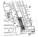
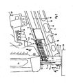
- Figures 1 and 2 show a nail driving device in the form of a gas-firing hammer 1 comprising, amongst other parts, housing 24 comprising a combustion engine and a fuel container, a handle 26, a battery 27, a trigger 23.
- a gas-firing hammer 1 further comprises a per se known barrel 3 with an actuator 25 which is arranged therealong and which debouches at the end of the barrel into an actuator head arranged around the barrel and having pointed tips which will, for instance, prevent shifting when the gas-firing hammer 1is actuated.
- the gas-firing hammer 1 further comprises a magazine 4 which is suitable for holding nails arranged in strips. These nails are arranged in the magazine such that the heads 21 of the nails are situated in the head guide channel 22.
- the shank of the nail with the tip arranged on the other end relative to the head, extends from the head guide channel 22 into the magazine.
- the length of the nail is herein such that it extends no further than the bottom edge 19 of the magazine.
- the shank herein extends between side walls 20 of the magazine, these side walls being provided with openings 18 which on the one hand save weight and on the other provide a view into the magazine.
- a pressure slide 17 is further provided in the magazine for the purpose of pressing the strip and nails in the direction of the barrel.
- a relatively large part of the magazine is necessarily open at the position of this slide.
- the relatively short nails 13 shown in the figure can hereby tilt transversely of the guide direction of the slide.
- a fastening member 15 is mounted at the beginning of the slide, wherein a guide rod 16 extends in the guide direction of the magazine from this fastening member. This preferably takes place in the manner shown in figure 2 , wherein guide rod 16 extends behind the slide 17.
- the slide 17 is preferably held under bias by means of a flat spring which can be wound up.
- an attachment 2 is placed over the actuator 25 and subsequently fixed in place by means of a screw element extending through an opening 7 provided in the attachment 2.
- the screw element may, for instance, be a screw having an M6 thread.
- the attachment 2 comprises a substantially flattened circular wall 5 which is placed around the actuator 25.
- Attachment 2 also comprises an end wall 6 having therein an opening 9 which is shown in figure 1 in line with the barrel 3.
- the attachment 2 also comprises a guide member in the formula flat plate 8, which extends partially through the substantially cylindrical wall 5 on the side of the magazine when the attachment is placed on the actuator 25.
- Flat plate 8 defines guide surface 10, which defines a part of the barrel of the gas-firing hammer.
- the shown relatively short nails 13 are hereby guided through the barrel, whereby there is no risk they will egress through the open side of the barrel suitable for allowing a long shank of the nail extending to a position close to the bottom edge of magazine 19.
- Flat plate 8 defines a stop surface 11 which has an angle relative to the barrel 3 such that it can press a number of, such as for instance the shown four nail tips, in the actuation position of the attachment 2 shown in figure 2 .
- the strip with nails is hereby once again positioned as well as possible relative to the barrel.
- Figure 1 shows the gas-firing hammer 1 in the passive state, wherein actuator 25, the nail driving rod 12 and the attachment 2 are situated in the rest position.
- actuator 25 the nail driving rod 12 and the attachment 2 are situated in the rest position.
- the attachment and the actuator 25 are pressed upward relative to the barrel 3 in the direction of arrow C by pressing the gas-firing hammer 1 downward in the direction of arrow A.
- the actuator 25, a pin of which extends along the barrel, is hereby driven into the gas-firing hammer 1 and the combustion engine is activated in per se known manner when trigger 23 is also actuated.
- the nail driving rod 12 is then thrust downward by the combustion engine and pushes the nail 13 downward through the barrel.
- the stop surface 11 of plate 8 of the attachment is pressed against the nail array, whereby the nail situated in the barrel is oriented as well as possible just before the nail driving rod 12 tears it from the strip and drives it into workpiece 28.
- the nail is guided downward by the barrel and also by guide wall 10 of plate 8 in appropriate manner through the barrel and eventually through opening 9 on the underside of end plate 6 of the attachment.
- FIG. 6 shows a bottom view of the attachment with the two side walls 20 of the magazine 4 shown extending on either side along plate 8 in the position of use of the attachment.
- the outer ends of side walls 20 of the magazine are shown with broken lines since in bottom view they have to be situated above the shown position of the attachment.
- the walls of the magazine 4 are provided for this purpose with a recess or opening 29.
- the shanks of long nails are hereby situated partially in this free space as they approach the open side of the barrel 3. Because such long nails are also guided through a higher part of the magazine, such long nails will hereby remain oriented in the lengthwise direction.
- the open side of the barrel 3 results in a further advantage of the present invention.
- a possible disruption during the feed and/or throughfeed of short nails in particular can be obviated in simple manner in that, because of the presence of much free space due to, among other things, the opening 29 in the magazine, the disruption can be remedied using the fingers and/or with a tool.
- the attachment 2 is removed there is, owing to such an arrangement, much space available for gaining access to the barrel.
- Such a significant advantage is not possible in a gas-firing hammer specifically suitable for the short tacks or 'haften' nails, among other reasons because there is very little space available in such a relatively short barrel.
- a further advantage of the shown embodiment is that the wall of the attachment 2 is flattened on two sides, whereby the distance of the nail to be inserted relative to the outer side of the wall is relatively small. Nails can hereby be inserted closely against a standing edge or wall.
- the same flattened wall can be envisaged on the front side of the attachment or for instance at any conceivable angle along the periphery of the wall subject to the application of the gas-firing hammer.
- the strength of the hereby weakened side wall can be obtained by the end plate and/or thickened portions in other parts of the attachment.
- the present invention is described in the foregoing on the basis of several preferred embodiments.
- the described device is for instance described on the basis of nails with a round head and at a determined angle.
- the invention is not limited hereto and can likewise be applied with nails having a D-shaped head and at any random angle.
- the invention is also described on the basis of a gas-firing hammer.
- the invention is however also suitable for a nail driving device with a powder-firing hammer or a nail driving device driven for instance by air pressure or an electric motor.
- the embodiment provides an attachment for a fastener gun having a barrel along which fasteners are fired and a magazine for holding fasteners having a first length and from which said first length fasteners are fed one by one into said barrel, said attachment being releasably securable to said nail gun and including a stop surface arranged such that when, in use, the attachment is secured to a said nail gun and the magazine of the nail gun is holding fasteners having a second length that is shorter than said first length, the stop surface is positioned to restrict movement in the firing direction of the fastener gun of at least the fastener in the magazine that is positioned to be next fed into the barrel.
- the nail gun comprises an actuator member slidable on said barrel and the attachment is releasably securable to the actuator member.
Landscapes
- Engineering & Computer Science (AREA)
- Mechanical Engineering (AREA)
- Chemical & Material Sciences (AREA)
- Combustion & Propulsion (AREA)
- Portable Nailing Machines And Staplers (AREA)
Claims (14)
- Dispositif d'enfoncement de clous pour enfoncer dans un objet au moins un premier clou de type relativement long et un second clou de type relativement court, ledit dispositif d'enfoncement de clous comprenant :une unité de percussion pour chasser un élément de fonçage ou de poussée (12) afin d'enfoncer le clou dans l'objet,un chargeur (4) pour contenir une réserve desdits clous,un canon (3) le long duquel ledit élément de fonçage ou de poussée dirige ledit clou dans l'objet, le canon présentant un orifice d'entrée latéral pour recevoir lesdits clous à partir du chargeur etun actionneur (25) apte à se déplacer le long du canon en réponse à une pression qui est produite lorsque le pistolet cloueur est poussé contre l'objet afin d'amorcer l'opération d'enfoncement, caractérisé parun accessoire (2) qui est apte à être monté de façon détachable sur ledit actionneur (25) afin de faciliter l'enfoncement dans l'objet du clou de type court (13) le long dudit canon, ledit accessoire comportant un élément de guidage (8) présentant une surface de guidage (10), la surface de guidage étant agencée de sorte que, lorsque ledit accessoire est monté sur ledit actionneur (25), il est reçu dans ledit orifice d'entrée latéral afin d'agir en coopération avec ledit canon (3) pour guider le clou de type court lorsqu'il est chassé le long dudit canon.
- Dispositif selon la revendication 1, l'accessoire (3) comprenant une partie extrémité d'actionnement sensiblement protectrice afin de protéger l'objet lorsque ladite pression est appliquée sur ledit actionneur lors de l'amorçage de l'opération d'enfoncement.
- Dispositif selon l'une quelconque des revendications précédentes, l'accessoire (2) comportant une surface d'arrêt (11) agencée de sorte que, lorsque ledit accessoire est monté sur ledit actionneur (25) et ledit chargeur (4) contient ledit type court de clous, la surface d'arrêt pourra limiter le mouvement du sens d'éjection du dispositif d'enfoncement de clous dudit au moins un clou dans le chargeur qui est positionné de façon à être le prochain à passer dans le canon.
- Dispositif selon la revendication 3, la surface d'arrêt (11) se prolongeant dans le sens de la longueur du chargeur (4) suivant un angle par rapport au canon qui correspond sensiblement à l'angle du chargeur par rapport au canon (3).
- Dispositif selon l'une quelconque des revendications précédentes, le chargeur (4) étant conçu pour guider au moins les pointes à la fois des clous de type long et des clous de type court.
- Dispositif selon la revendication 5, le chargeur (4) étant pourvu d'un ou de deux guides (16) pour empêcher le basculement des clous de type court suivant un sens qui diffère du sens d'alimentation du chargeur.
- Dispositif selon l'une quelconque des revendications précédentes, l'accessoire (2) comprenant au moins une portion aplanie dans une paroi latérale de celui-ci.
- Dispositif selon la revendication 1, l'accessoire comprenant en outre :un corps sensiblement cylindrique ou cylindrique aplani monté de façon détachable sur ledit actionneur (25),une surface d'extrémité sensiblement plane avec un passage traversant qui est aligné avec le canon lorsque le corps est monté sur l'actionneur (25), etledit élément de guidage (8) comportant un élément sensiblement plat ou similaire à une plaque (8) qui définit ladite surface de guidage.
- Accessoire pour un dispositif d'enfoncement de clous possédant un canon (3) le long duquel sont chassés des clous ayant une première longueur et des clous ayant une seconde longueur laquelle est moins importante que ladite première longueur, un actionneur (25) coulissable le long dudit canon en réponse à une force de réaction qui est produite lorsque le dispositif d'enfoncement de clous est pressé contre un obj et dans lequel un clou est destiné à être enfoncé, un chargeur (4) pour contenir une réserve desdits clous et à partir duquel lesdits clous peuvent être alimentés un par un dans ledit canon à travers un orifice d'entrée latéral dudit canon, ledit accessoire (2) comportant un corps sensiblement cylindrique ou cylindrique aplani monté de façon détachable sur ledit actionneur et un élément de guidage (8) présentant une surface de guidage (10), la surface de guidage étant agencée de sorte que, lorsque ledit corps est monté sur ledit actionneur, la surface de guidage est reçue dans ledit orifice d'entrée latéral afin d'agir en coopération avec ledit canon pour guider le clou de seconde longueur lorsqu'il est chassé le long dudit canon afin de faciliter l'éjection le long dudit canon de clous ayant ladite seconde longueur.
- Accessoire selon la revendication 9, ledit corps sensiblement cylindrique ou cylindrique aplani étant une partie extrémité d'actionnement sensiblement protectrice (5) qui y reçoit une portion de l'actionneur et ledit élément de guidage (8) faisant saillie à partir de ladite partie extrémité d'actionnement sensiblement protectrice afin de définir une surface d'arrêt (11) qui se prolonge dans un plan transversal par rapport à un axe longitudinal de ladite partie extrémité d'actionnement sensiblement protectrice pour limiter le mouvement du sens d'éjection du dispositif d'enfoncement de clous d'au moins un premier clou de seconde longueur dans ledit chargeur qui est positionné de façon à être le prochain à passer dans le canon.
- Accessoire selon la revendication 10, ladite surface de guidage (10) se prolongeant dans un plan parallèle par rapport audit axe longitudinal de la partie extrémité d'actionnement sensiblement protectrice (5).
- Accessoire selon la revendication 11, ledit corps sensiblement cylindrique ou cylindrique aplani définissant une ouverture pour le passage desdits clous de seconde longueur éjectés le long dudit canon, ledit corps sensiblement cylindrique ou cylindrique aplani et une paroi d'extrémité de celui-ci définissant une fente se prolongeant dans le sens de la longueur dans lequel ledit élément de guidage (8) est reçu de sorte qu'une portion d'un bord dudit élément de guidage, lequel définit ladite surface de guidage (10), se prolonge dans ladite partie extrémité d'actionnement sensiblement protectrice.
- Accessoire selon la revendication 9, ledit corps sensiblement cylindrique ou cylindrique aplani étant une partie extrémité d'actionnement sensiblement protectrice qui reçoit une portion extrémité libre dudit actionneur (25) de sorte que l'objet, dans lequel un clou est destiné à être enfoncé, n'est pas touché par ladite portion extrémité libre afin de protéger ledit obj et pendant une opération d'enfoncement de clou.
- Procédé d'enfoncement de clous comprenant la fixation d'un accessoire, selon l'une quelconque des revendications 9 à 13, sur ledit actionneur (25) d'un dispositif d'enfoncement de clous.
Applications Claiming Priority (1)
| Application Number | Priority Date | Filing Date | Title |
|---|---|---|---|
| NL1032352A NL1032352C2 (nl) | 2006-08-22 | 2006-08-22 | Nagelindrijfinrichting, hulpstuk daarvoor en werkwijze. |
Publications (3)
| Publication Number | Publication Date |
|---|---|
| EP1892061A1 EP1892061A1 (fr) | 2008-02-27 |
| EP1892061B1 true EP1892061B1 (fr) | 2012-08-01 |
| EP1892061B8 EP1892061B8 (fr) | 2012-09-05 |
Family
ID=37708173
Family Applications (1)
| Application Number | Title | Priority Date | Filing Date |
|---|---|---|---|
| EP20070016316 Not-in-force EP1892061B8 (fr) | 2006-08-22 | 2007-08-21 | Outil pour enfoncer des clous, accessoire pour cet outil et procédé |
Country Status (2)
| Country | Link |
|---|---|
| EP (1) | EP1892061B8 (fr) |
| NL (1) | NL1032352C2 (fr) |
Families Citing this family (3)
| Publication number | Priority date | Publication date | Assignee | Title |
|---|---|---|---|---|
| WO2012065090A1 (fr) * | 2010-11-12 | 2012-05-18 | Illinois Tool Works Inc. | Outil d'enfoncement d'élément de fixation |
| CN104227659B (zh) * | 2013-06-21 | 2016-11-23 | 苏州宝时得电动工具有限公司 | 带有钉盒的电动榔头 |
| US10493607B2 (en) | 2016-06-28 | 2019-12-03 | Black & Decker, Inc. | Concrete nailer having magazine cutout for deep tracks |
Family Cites Families (3)
| Publication number | Priority date | Publication date | Assignee | Title |
|---|---|---|---|---|
| US5437404A (en) * | 1993-07-13 | 1995-08-01 | Illinois Tool Works Inc. | Adjustable shear block assembly |
| US5615819A (en) * | 1995-10-03 | 1997-04-01 | Hou; Chang Feng-Mei | Nail magazine structure of a power nailer |
| US6896165B1 (en) * | 2004-03-22 | 2005-05-24 | Bentley Fastening Tools Co., Ltd. | Device for preventing short nails of a nail gun from being deadlocked |
-
2006
- 2006-08-22 NL NL1032352A patent/NL1032352C2/nl not_active IP Right Cessation
-
2007
- 2007-08-21 EP EP20070016316 patent/EP1892061B8/fr not_active Not-in-force
Also Published As
| Publication number | Publication date |
|---|---|
| EP1892061B8 (fr) | 2012-09-05 |
| NL1032352C2 (nl) | 2008-02-25 |
| EP1892061A1 (fr) | 2008-02-27 |
Similar Documents
| Publication | Publication Date | Title |
|---|---|---|
| CA2422447C (fr) | Outil de charpentage a reglage automatique de la dimension des fixations | |
| EP2440373B1 (fr) | Pointe de contact avec pièce par guidage aveugle pour un outil de fixation | |
| US4380312A (en) | Stapling tool | |
| CA2104490C (fr) | Mecanisme de positionnement pour outil a moteur | |
| US7506789B2 (en) | Continuous feed cap system | |
| US6032848A (en) | Fastener-driving tool having wear guard defining fastener-guiding surface | |
| US6679414B2 (en) | Interchangeable magazine for a tool | |
| US20050001007A1 (en) | Pneumatic nailer | |
| US20040011845A1 (en) | Adapter for nail gun for installing siding | |
| EP0360573A2 (fr) | Outil d'enfoncement d'attaches | |
| EP1951478B1 (fr) | Machine a clouer a combustion avec element de contact de piece | |
| US7070079B2 (en) | No-mar tip for fastening tool | |
| CA2418828C (fr) | Systeme a rails pour outil agrafeur | |
| US6986448B2 (en) | Fastener driving tool for spacing object from substrate | |
| EP1892061A1 (fr) | Outil pour enfoncer des clous, accessoire pour cet outil et procédé | |
| US7303105B2 (en) | Arcuate fastener nailing device for hardwood flooring | |
| EP1880805A1 (fr) | Cloueur et système d'alimentation | |
| EP3720658B1 (fr) | Mécanisme de verrouillage d'embout pour un outil de fixation | |
| US6123245A (en) | Nailer with nail guiding channel | |
| US20120024930A1 (en) | Powered stapler and method of operating same | |
| EP1880806A1 (fr) | Système de collecte de capuchon | |
| JP3117696U (ja) | 釘打機の釘詰まり解消工具 | |
| WO2004085119A2 (fr) | Outil mecanique pour des attaches de perforation de metal |
Legal Events
| Date | Code | Title | Description |
|---|---|---|---|
| PUAI | Public reference made under article 153(3) epc to a published international application that has entered the european phase |
Free format text: ORIGINAL CODE: 0009012 |
|
| AK | Designated contracting states |
Kind code of ref document: A1 Designated state(s): AT BE BG CH CY CZ DE DK EE ES FI FR GB GR HU IE IS IT LI LT LU LV MC MT NL PL PT RO SE SI SK TR |
|
| AX | Request for extension of the european patent |
Extension state: AL BA HR MK YU |
|
| 17P | Request for examination filed |
Effective date: 20080827 |
|
| AKX | Designation fees paid |
Designated state(s): AT BE CH DE LI NL |
|
| R17P | Request for examination filed (corrected) |
Effective date: 20080827 |
|
| RBV | Designated contracting states (corrected) |
Designated state(s): AT BE BG CH CY CZ DE DK EE ES FI FR GB GR HU IE IS IT LI LT LU LV MC MT NL PL PT RO SE SI SK TR |
|
| RTI1 | Title (correction) |
Free format text: NAIL DRIVING DEVICE, ATTACHMENT THEREFOR AND METHOD |
|
| GRAP | Despatch of communication of intention to grant a patent |
Free format text: ORIGINAL CODE: EPIDOSNIGR1 |
|
| GRAS | Grant fee paid |
Free format text: ORIGINAL CODE: EPIDOSNIGR3 |
|
| GRAA | (expected) grant |
Free format text: ORIGINAL CODE: 0009210 |
|
| AK | Designated contracting states |
Kind code of ref document: B1 Designated state(s): AT BE BG CH CY CZ DE DK EE ES FI FR GB GR HU IE IS IT LI LT LU LV MC MT NL PL PT RO SE SI SK TR |
|
| REG | Reference to a national code |
Ref country code: GB Ref legal event code: FG4D |
|
| REG | Reference to a national code |
Ref country code: AT Ref legal event code: REF Ref document number: 568408 Country of ref document: AT Kind code of ref document: T Effective date: 20120815 Ref country code: CH Ref legal event code: EP |
|
| RAP2 | Party data changed (patent owner data changed or rights of a patent transferred) |
Owner name: BLACK & DECKER INC. |
|
| REG | Reference to a national code |
Ref country code: IE Ref legal event code: FG4D |
|
| REG | Reference to a national code |
Ref country code: DE Ref legal event code: R096 Ref document number: 602007024264 Country of ref document: DE Effective date: 20120927 |
|
| REG | Reference to a national code |
Ref country code: NL Ref legal event code: T3 |
|
| REG | Reference to a national code |
Ref country code: LT Ref legal event code: MG4D Effective date: 20120801 |
|
| PG25 | Lapsed in a contracting state [announced via postgrant information from national office to epo] |
Ref country code: LT Free format text: LAPSE BECAUSE OF FAILURE TO SUBMIT A TRANSLATION OF THE DESCRIPTION OR TO PAY THE FEE WITHIN THE PRESCRIBED TIME-LIMIT Effective date: 20120801 Ref country code: IS Free format text: LAPSE BECAUSE OF FAILURE TO SUBMIT A TRANSLATION OF THE DESCRIPTION OR TO PAY THE FEE WITHIN THE PRESCRIBED TIME-LIMIT Effective date: 20121201 Ref country code: FI Free format text: LAPSE BECAUSE OF FAILURE TO SUBMIT A TRANSLATION OF THE DESCRIPTION OR TO PAY THE FEE WITHIN THE PRESCRIBED TIME-LIMIT Effective date: 20120801 Ref country code: CY Free format text: LAPSE BECAUSE OF FAILURE TO SUBMIT A TRANSLATION OF THE DESCRIPTION OR TO PAY THE FEE WITHIN THE PRESCRIBED TIME-LIMIT Effective date: 20120801 |
|
| PG25 | Lapsed in a contracting state [announced via postgrant information from national office to epo] |
Ref country code: SI Free format text: LAPSE BECAUSE OF FAILURE TO SUBMIT A TRANSLATION OF THE DESCRIPTION OR TO PAY THE FEE WITHIN THE PRESCRIBED TIME-LIMIT Effective date: 20120801 Ref country code: PT Free format text: LAPSE BECAUSE OF FAILURE TO SUBMIT A TRANSLATION OF THE DESCRIPTION OR TO PAY THE FEE WITHIN THE PRESCRIBED TIME-LIMIT Effective date: 20121203 Ref country code: SE Free format text: LAPSE BECAUSE OF FAILURE TO SUBMIT A TRANSLATION OF THE DESCRIPTION OR TO PAY THE FEE WITHIN THE PRESCRIBED TIME-LIMIT Effective date: 20120801 Ref country code: PL Free format text: LAPSE BECAUSE OF FAILURE TO SUBMIT A TRANSLATION OF THE DESCRIPTION OR TO PAY THE FEE WITHIN THE PRESCRIBED TIME-LIMIT Effective date: 20120801 Ref country code: GR Free format text: LAPSE BECAUSE OF FAILURE TO SUBMIT A TRANSLATION OF THE DESCRIPTION OR TO PAY THE FEE WITHIN THE PRESCRIBED TIME-LIMIT Effective date: 20121102 Ref country code: LV Free format text: LAPSE BECAUSE OF FAILURE TO SUBMIT A TRANSLATION OF THE DESCRIPTION OR TO PAY THE FEE WITHIN THE PRESCRIBED TIME-LIMIT Effective date: 20120801 |
|
| PG25 | Lapsed in a contracting state [announced via postgrant information from national office to epo] |
Ref country code: MC Free format text: LAPSE BECAUSE OF NON-PAYMENT OF DUE FEES Effective date: 20120831 |
|
| PG25 | Lapsed in a contracting state [announced via postgrant information from national office to epo] |
Ref country code: RO Free format text: LAPSE BECAUSE OF FAILURE TO SUBMIT A TRANSLATION OF THE DESCRIPTION OR TO PAY THE FEE WITHIN THE PRESCRIBED TIME-LIMIT Effective date: 20120801 Ref country code: CZ Free format text: LAPSE BECAUSE OF FAILURE TO SUBMIT A TRANSLATION OF THE DESCRIPTION OR TO PAY THE FEE WITHIN THE PRESCRIBED TIME-LIMIT Effective date: 20120801 Ref country code: DK Free format text: LAPSE BECAUSE OF FAILURE TO SUBMIT A TRANSLATION OF THE DESCRIPTION OR TO PAY THE FEE WITHIN THE PRESCRIBED TIME-LIMIT Effective date: 20120801 Ref country code: ES Free format text: LAPSE BECAUSE OF FAILURE TO SUBMIT A TRANSLATION OF THE DESCRIPTION OR TO PAY THE FEE WITHIN THE PRESCRIBED TIME-LIMIT Effective date: 20121112 Ref country code: EE Free format text: LAPSE BECAUSE OF FAILURE TO SUBMIT A TRANSLATION OF THE DESCRIPTION OR TO PAY THE FEE WITHIN THE PRESCRIBED TIME-LIMIT Effective date: 20120801 |
|
| REG | Reference to a national code |
Ref country code: IE Ref legal event code: MM4A |
|
| PG25 | Lapsed in a contracting state [announced via postgrant information from national office to epo] |
Ref country code: IT Free format text: LAPSE BECAUSE OF FAILURE TO SUBMIT A TRANSLATION OF THE DESCRIPTION OR TO PAY THE FEE WITHIN THE PRESCRIBED TIME-LIMIT Effective date: 20120801 Ref country code: SK Free format text: LAPSE BECAUSE OF FAILURE TO SUBMIT A TRANSLATION OF THE DESCRIPTION OR TO PAY THE FEE WITHIN THE PRESCRIBED TIME-LIMIT Effective date: 20120801 |
|
| PLBE | No opposition filed within time limit |
Free format text: ORIGINAL CODE: 0009261 |
|
| STAA | Information on the status of an ep patent application or granted ep patent |
Free format text: STATUS: NO OPPOSITION FILED WITHIN TIME LIMIT |
|
| 26N | No opposition filed |
Effective date: 20130503 |
|
| PG25 | Lapsed in a contracting state [announced via postgrant information from national office to epo] |
Ref country code: IE Free format text: LAPSE BECAUSE OF NON-PAYMENT OF DUE FEES Effective date: 20120821 Ref country code: BG Free format text: LAPSE BECAUSE OF FAILURE TO SUBMIT A TRANSLATION OF THE DESCRIPTION OR TO PAY THE FEE WITHIN THE PRESCRIBED TIME-LIMIT Effective date: 20121101 |
|
| REG | Reference to a national code |
Ref country code: DE Ref legal event code: R097 Ref document number: 602007024264 Country of ref document: DE Effective date: 20130503 |
|
| PG25 | Lapsed in a contracting state [announced via postgrant information from national office to epo] |
Ref country code: MT Free format text: LAPSE BECAUSE OF FAILURE TO SUBMIT A TRANSLATION OF THE DESCRIPTION OR TO PAY THE FEE WITHIN THE PRESCRIBED TIME-LIMIT Effective date: 20120801 |
|
| PG25 | Lapsed in a contracting state [announced via postgrant information from national office to epo] |
Ref country code: TR Free format text: LAPSE BECAUSE OF FAILURE TO SUBMIT A TRANSLATION OF THE DESCRIPTION OR TO PAY THE FEE WITHIN THE PRESCRIBED TIME-LIMIT Effective date: 20120801 |
|
| PG25 | Lapsed in a contracting state [announced via postgrant information from national office to epo] |
Ref country code: LU Free format text: LAPSE BECAUSE OF NON-PAYMENT OF DUE FEES Effective date: 20120821 |
|
| PG25 | Lapsed in a contracting state [announced via postgrant information from national office to epo] |
Ref country code: HU Free format text: LAPSE BECAUSE OF FAILURE TO SUBMIT A TRANSLATION OF THE DESCRIPTION OR TO PAY THE FEE WITHIN THE PRESCRIBED TIME-LIMIT Effective date: 20070821 |
|
| REG | Reference to a national code |
Ref country code: FR Ref legal event code: PLFP Year of fee payment: 10 |
|
| REG | Reference to a national code |
Ref country code: FR Ref legal event code: PLFP Year of fee payment: 11 |
|
| PGFP | Annual fee paid to national office [announced via postgrant information from national office to epo] |
Ref country code: NL Payment date: 20170814 Year of fee payment: 11 |
|
| PGFP | Annual fee paid to national office [announced via postgrant information from national office to epo] |
Ref country code: GB Payment date: 20170719 Year of fee payment: 11 Ref country code: GB Payment date: 20170816 Year of fee payment: 11 Ref country code: CH Payment date: 20170814 Year of fee payment: 11 |
|
| PGFP | Annual fee paid to national office [announced via postgrant information from national office to epo] |
Ref country code: AT Payment date: 20170725 Year of fee payment: 11 |
|
| REG | Reference to a national code |
Ref country code: FR Ref legal event code: PLFP Year of fee payment: 12 |
|
| PGFP | Annual fee paid to national office [announced via postgrant information from national office to epo] |
Ref country code: BE Payment date: 20180614 Year of fee payment: 12 |
|
| PGFP | Annual fee paid to national office [announced via postgrant information from national office to epo] |
Ref country code: FR Payment date: 20180712 Year of fee payment: 12 |
|
| REG | Reference to a national code |
Ref country code: DE Ref legal event code: R119 Ref document number: 602007024264 Country of ref document: DE |
|
| REG | Reference to a national code |
Ref country code: CH Ref legal event code: PL |
|
| REG | Reference to a national code |
Ref country code: NL Ref legal event code: MM Effective date: 20180901 |
|
| REG | Reference to a national code |
Ref country code: AT Ref legal event code: MM01 Ref document number: 568408 Country of ref document: AT Kind code of ref document: T Effective date: 20180821 |
|
| GBPC | Gb: european patent ceased through non-payment of renewal fee |
Effective date: 20180821 |
|
| PG25 | Lapsed in a contracting state [announced via postgrant information from national office to epo] |
Ref country code: AT Free format text: LAPSE BECAUSE OF NON-PAYMENT OF DUE FEES Effective date: 20180821 Ref country code: LI Free format text: LAPSE BECAUSE OF NON-PAYMENT OF DUE FEES Effective date: 20180831 Ref country code: CH Free format text: LAPSE BECAUSE OF NON-PAYMENT OF DUE FEES Effective date: 20180831 |
|
| PG25 | Lapsed in a contracting state [announced via postgrant information from national office to epo] |
Ref country code: NL Free format text: LAPSE BECAUSE OF NON-PAYMENT OF DUE FEES Effective date: 20180901 |
|
| PG25 | Lapsed in a contracting state [announced via postgrant information from national office to epo] |
Ref country code: DE Free format text: LAPSE BECAUSE OF NON-PAYMENT OF DUE FEES Effective date: 20190301 |
|
| PG25 | Lapsed in a contracting state [announced via postgrant information from national office to epo] |
Ref country code: GB Free format text: LAPSE BECAUSE OF NON-PAYMENT OF DUE FEES Effective date: 20180821 |
|
| REG | Reference to a national code |
Ref country code: BE Ref legal event code: MM Effective date: 20190831 |
|
| PG25 | Lapsed in a contracting state [announced via postgrant information from national office to epo] |
Ref country code: FR Free format text: LAPSE BECAUSE OF NON-PAYMENT OF DUE FEES Effective date: 20190831 |
|
| PG25 | Lapsed in a contracting state [announced via postgrant information from national office to epo] |
Ref country code: BE Free format text: LAPSE BECAUSE OF NON-PAYMENT OF DUE FEES Effective date: 20190831 |