EP1892100A2 - Bedienungstisch für Druckmaschinen - Google Patents
Bedienungstisch für Druckmaschinen Download PDFInfo
- Publication number
- EP1892100A2 EP1892100A2 EP07002077A EP07002077A EP1892100A2 EP 1892100 A2 EP1892100 A2 EP 1892100A2 EP 07002077 A EP07002077 A EP 07002077A EP 07002077 A EP07002077 A EP 07002077A EP 1892100 A2 EP1892100 A2 EP 1892100A2
- Authority
- EP
- European Patent Office
- Prior art keywords
- paper
- width direction
- printing
- printed paper
- sample printed
- Prior art date
- Legal status (The legal status is an assumption and is not a legal conclusion. Google has not performed a legal analysis and makes no representation as to the accuracy of the status listed.)
- Withdrawn
Links
Images



Classifications
-
- B—PERFORMING OPERATIONS; TRANSPORTING
- B41—PRINTING; LINING MACHINES; TYPEWRITERS; STAMPS
- B41F—PRINTING MACHINES OR PRESSES
- B41F33/00—Indicating, counting, warning, control or safety devices
-
- B—PERFORMING OPERATIONS; TRANSPORTING
- B41—PRINTING; LINING MACHINES; TYPEWRITERS; STAMPS
- B41F—PRINTING MACHINES OR PRESSES
- B41F33/00—Indicating, counting, warning, control or safety devices
- B41F33/0009—Central control units
Definitions
- the present invention relates to a manipulation desk for controlling a supply of ink for each of a plurality of ink supply zones split in the width direction of printing paper in a printing machine, and more particularly to a manipulation desk for printing machines that can keep up with width changes of printing paper.
- the operator adjusts a supply of ink by hand to adjust the density and tone of images and characters that are printed.
- Such an ink supply adjustment is performed for each of the ink supply widths split in the axial direction of the printing cylinders (the plate cylinder and blanket cylinder), that is, in the printing width direction.
- the operator manipulates the ink supply adjustment switches provided so as to correspond to the ink supply widths, thereby adjusting a supply of ink.
- the newspaper sides of two-page-width are made using a four-page-wide web. That is, printing is performed on a four-page-wide web through printing cylinders, and the center of the four-page-wide web is subsequently split into two two-page-wide spaces by a slitter.
- Indischarging newspapers, two-page-wide spaces are overlaid in page order and fed to a folding machine, in which they are folded at the center of the two-page width and further at the up-and-down center of one page to produce a folded newspaper.
- Patent Document 1 Japanese Patent Laid-Open Publication No. 2004-338814 .
- the Patent Document 1 discloses a rotary web printing machine in which webs from a plurality of web feed sections are printed in a plurality of printing sections and folded in a folding section.
- This rotary web printing machine is equipped with turn bars for turning the moving directions of the webs before theygo into the folding section, andaplurality of triangular plates for guiding the webs to the folding section. By selecting turn bars or performing position adjustments, webs of various widths can be freely positioned with respect to the plurality of triangular plates.
- the operator selects an ink adjustment switch based on the page position of a printed paper required to be adjusted and manipulates the selected switch. This can easily cause the occurrence of misjudgment and increase waste paper.
- the present invention has been made in view of the circumstances described above. Accordingly, it is the primary object of the present invention to provide a manipulation desk for printing machines that is capable of easily recognizing the position of a target ink adjustment switch so that the occurrence of waste paper can be prevented and a supply of ink can be properly adjusted, even when the width of a printing web is changed.
- a manipulation desk for controlling a supply of ink for each of a plurality of ink supply zones split in a width direction of printing paper in a printing machine.
- the manipulation desk comprises four major components: (1) a paper table for placing a sample printed paper thereon; (2) a plurality of ink adjustment switches disposed near the paper table so as to correspond to the ink supply zones along a width direction of the sample printed paper placed on the paper table; (3) a plurality of indicators arranged on the paper table along the width direction of the sample printed paper placed on the paper table; and (4) control means for selecting and lighting an indicator of the plurality of indicators that is used to position a specific position of the sample printed paper so that a first width direction position of the sample printed paper relative to the plurality of ink adjustment switches on the paper table is the same position as a second width direction position relative to the plurality of ink supply zones of a print image that corresponds to the sample printed paper.
- the first width direction position of the sample printed paper relative to the plurality of ink adjustment switches on the paper table becomes the same position as the second width direction position relative to the plurality of ink supply zones of a print image that corresponds to the sample printed paper. Therefore, if a corresponding ink adjustment switch is manipulated by checking the sample printed paper placed on the paper table, the required ink supply of the ink supply zone relative to a print image that corresponds to the sample printed paper is adjusted.
- the position of an ink adjustment switch to be manipulated can be easily recognized, whereby the occurrence of waste paper can be suppressed and a supply of ink can be properly adjusted.
- the aforementioned printing machine may be a rotary web printing machine; the aforementioned printing paper may be a printing web with a four-page width; the aforementioned sample printed paper may be one of two two-page-wide spaces into which the printing web is split in a width direction thereof; and the aforementioned control means may calculate the second width direction position, based on a third width direction position relative to the printing machine of a printing area equivalent to the two-page-wide space.
- the aforementioned control means preferably grasps the third width direction position, based on a position of a printing plate of the printing area relative to a necessary printing cylinder of the printing machine and on a width of the printing web obtained from a web holding unit which holds the printing web.
- the web width can be precisely calculated. This makes it possible to grasp the width direction position relative to the printing machine of a space or its printing area, on the basis of a calculated web width and the position of the printing plate relative to the printing cylinder.
- the specific position of the sample printed paper is preferably the center position in the width direction of the two-page-wide space, or either or both of end positions in the width direction of the two-page-wide space.
- the aforementioned indicators preferably comprise light-emitting diode lamps, and preferably the aforementioned plurality of ink adjustment switches are transversely arranged in front of the paper table.
- the aforementioned indicators are light-emitting diode lamps, small indicators can be adopted and therefore fine positioning becomes possible.
- the aforementioned plurality of ink adjustment switches are transversely arranged in front of the paper table, controllability relating to ink supply adjustments is enhanced.
- a printing machine according to the present invention is equipped with the above-described manipulation desk.
- a print according to the present invention is obtained by the above-described printing machine.
- a method which is used in a manipulation desk comprising a paper table for placing a sample printed paper thereon, a plurality of ink adjustment switches disposed along a width direction of the paper table so as to correspond to ink supply zones, a plurality of indicators arranged in parallel with the plurality of ink adjustment switches along a width direction of the paper table, and control means for selecting and lighting a specific indicator of the plurality of indicators, and which lights the specific indicator to guide positioning of the sample printed paper.
- the method of the present invention comprises a step of inputting information of a width direction mounting position of a printing plate for each printed paper that is mounted on a plate cylinder of a printing machine, to the control means; and a step of selecting and lighting a specific indicator of the plurality of indicators based on the input width direction mounting position information by the control means so that a width direction position of the sample printed paper relative to the plurality of ink adjustment switches on the paper table is the same position as a width direction position relative to the plurality of ink supply zones of a print image that corresponds to the sample printed paper, and thereby guiding positioning of the sample printed paper.
- the first width direction position of the sample printed paper relative to the plurality of ink adjustment switches on the paper table becomes the same position as the second width direction position relative to the plurality of ink supply zones of a print image that corresponds to the sample printed paper. Therefore, if a corresponding ink adjustment switch is manipulated by checking the sample printed paper placed on the paper table, the required ink supply of the ink supply zone relative to a print image that corresponds to the sample printed paper is adjusted.
- the position of an ink adjustment switch to be manipulated can be easily recognized, whereby the occurrence of waste paper can be suppressed and a supply of ink can be properly adjusted.
- the width directionmountingposition information is preferably used detection information obtained from a position sensor that is attached to the plate cylinder for detecting the width direction mounting position.
- a print ing method is a method of carrying out printing by adjusting a plurality of ink adjustment switches, using the above-described method of guiding the positioning of the sample printed paper.
- the first width direction position of the sample printed paper relative to the plurality of ink adjustment switches on the paper table becomes the same position as the second width direction position relative to the plurality of ink supply zones of a print image that corresponds to the sample printed paper. Therefore, if a corresponding ink adjustment switch is manipulated by checking the sample printed paper placed on the paper table, the required ink supply of the ink supply zone relative to a print image that corresponds to the sample printed paper is adjusted.
- the position of an ink adjustment switch to be manipulated can be easily recognized, whereby the occurrence of waste paper can be suppressed and a supply of ink can be properly adjusted.
- the aforementioned printing machine is a rotary web printing machine
- the aforementioned printing paper is a printing web with a four-page width
- the aforementioned sample printed paper is one of two two-page-wide spaces into which the printing web is split in a width direction thereof
- the aforementioned control means calculates the second width direction position, based on a third width direction position relative to the printing machine of a printing area equivalent to the two-page-wide spaces, then it becomes possible to easily and precisely select an indicator that is to be lit.
- the aforementioned control means grasps the third width direction position, based on a position of a printing plate of the printing area relative to a necessary printing cylinder of the printing machine and on a width of the printing web obtained from a web holding unit which holds the printing web, then it becomes possible to easily and reliably grasp the width direction position relative to the printing machine of a print region equivalent to the two-page-wide space.
- the specific position of the sample printed paper is the center position in the width direction of the two-page-wide space, the sample printed paper can be properly placed on the paper table. If the specific position of the sample printed paper is either of the end positions in the width direction of the two-page-wide space, when the width of a web is greatly changed, there are cases where it is misjudged which end is aligned with the indicator.
- the aforementioned indicators are light-emitting diode lamps, small indicators can be adopted and therefore fine positioning becomes possible.
- the aforementioned ink adjustment switches are transversely arranged in front of the paper table, controllability relating to ink supply adjustments is enhanced.
- FIGS. 1 to 8 show a printing machine manipulation desk and a printing machine according to a preferred embodiment of the present invention, and based on these figures, the preferred embodiment will be described.
- FIGS. 5 to 8 there is shown a rotary web printing machine that is a printing machine according to the preferred embodiment of the present invention.
- FIGS. 5 to 7 show the rotary web printing machine described in the aforementioned Patent Document 1.
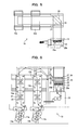
- FIG. 5 is a plan view showing one of the rotary web printing machines arranged transversely
- FIG. 6 is a front view of the rotary web printing machine shown in FIG. 5
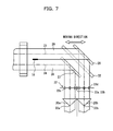
- FIG. 7 is a plan view showing the relationship between a printing plate, a slitter, a turn bar, a paper press roller, and a triangular plate in the case of printing a web width (non-standard web width) which differs from a stand web width.
- FIG. 8 is a schematically perspective view of the rotary web printing machine showing the relationship of printing space to a printing web.
- a first web feed section 11a and a first printing section 12a are arranged in parallel with a second web feed section 11b and a second printing section 12b, and a first web 15a and a second web 15b travel straight until they reach a folding section 13.
- the folding section 13 is arranged at a right angle to the row of the web feed sections 11a, 11b and row of printing sections 12a, 12b, and a folded print is discharged in the direction indicated by an arrow in FIG. 5.
- the traveling direction of the web 30 is turned 90 degrees by the turn bar 28 so that the crease 24 of the web 30 coincides with the extreme end 33a of the triangular plate 20a.
- the two webs 29, 30 are both turned in direction by the turn bar 32 that is at a standard position.
- This turn bar 32 has a length corresponding to the full web width of a standard web, and the turn bars 27, 28 for narrow web widths other than that are disposed in paths differing from that of the turn bar 32.
- the positions of the triangular plates 20a, 20b are at the positions where the creases 23, 24 of the webs 29, 30 coincide with the extreme ends 33b, 33a of the triangular plates 20b, 20a, so they do not need to be moved because of a change in web width.
- the turn bars 27, 28 when switching a web width from newspaper printing (standard web width printing) to non-standard web width printing, components requiring a change in position are the turn bars 27, 28.
- the positions of the turn bars 27, 28 can be adjusted by moving four rollers 22a, 22b, 22c, 22d of the paper press rollers 22 provided on the drag rollers on the triangular plates.
- the web needs to be moved along a path in which the turn bar 32 is arranged. This adjustment can be performed by moving only the aforementioned four rollers 22a, 22b, 22c, 22d in the opposite direction.
- Such a rotary web printing machine is equipped with ink supplyunits for supplying ink to the printing cylinders (the plate cylinder and blanket cylinder) of the printing sections 12a, 12b.
- Each ink supply unit has an array of ink keys arranged in the web width direction (axial direction of the printing cylinder), and by adjusting the opening degree of each ink key, a supply of ink can be adjusted for each ink key width (each ink supply zone) .
- a manipulation desk 1 such as that shown in FIG. 1 is installed in an printing operator room or the like.
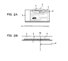
- the manipulation desk 1 is provided with a paper table 2 for placing a sample printed paper 5 thereon, and a plurality of ink adjustment switches (ink adjustment keys) 3 arranged in front of the paper table 2 along the width direction of the sample printed paper 5 placed on the paper table 2.
- the plurality of ink adjustment switches 3 are arranged to correspond to the actual intervals of the ink supply zones. Note that the above-described configuration of the manipulation desk 1 is well known in the prior art.
- a plurality of light-emitting diode (LED) lamps 4 as indicators are arranged along the width direction of the sample printed paper 5 placed on the paper table 2.
- LED lamps 4 are used for the positioning of the sample printed paper 5 that is placed on the paper table 2, and are arranged transversely on the upper portion of the paper table 2 so that they are not hidden with the sample printed paper 5 placed on the paper table 2 and are not away from the sample printed paper 5 placed on the paper table 2.
- the lighting of the LED lamps 4 is controlled through a controller 6 installed on the manipulation desk 1.
- the controller 6 functions to select and light any one of the LED lamps 4.
- a position sensor for detecting a mounting position of a printing plate may be attached to a plate cylinder for inputting the detection information from the sensor to the controller 6, or the mounting position of a printing plate for each page may be input to the controller 6 by hand.
- the printing machine of the preferred embodiment is the above-described rotary web printing machine, and as described above, printing paper is the four-page-wide web 15, and the sample printed paper 5 to be placed on the paper table 2 is equivalent to one of two two-page-wide spaces into which the four-page-wide web 5 is split in the width direction. Therefore, the mounting position of the printing plate for each page in the preferred embodiment means the mounting position of the printing plate relative to the two-page-wide space.
- the width direction position of the printed paper relative to the plate cylinder is the width direction position of the printed paper relative to each ink supply zone (or each ink key) .
- the determination of the central position in the width direction of the two-page-wide space relative to the plate cylinder makes it possible to precisely recognize the entire width direction position of the two-page-wide space. In a stand which holds webs (e.g., a mill roll stand in the web feed section), even when the width of a web is increased or reduced, the web width can be precisely calculated. This makes it possible to grasp the width direction position relative to the printing machine of a space or its printing area, on the basis of a calculated web width and the position of the printing plate relative to the printing cylinder.
- the ink adjustment switches 3 of the manipulation desk 1 are at the positions corresponding to the ink supply zones, so any one of the lamps 4 can be selected and lit so that the width direction position relative to the ink adjustment switches 3 of a two-page-wide space (which is a sample printed paper placed on the paper table 2) is the same as the width direction position relative to the plate cylinder of the printing plate corresponding to this sample printed paper (i.e., the width direction position relative to the ink supply zones of a print image corresponding to the sample printed paper).
- the controller 6 is able to light the LED lamp 4a of the paper table 2 that is away from a position corresponding to that reference position by d1.
- the manipulation desk 1 of the printing machine is constructed as described above. Therefore, for example, as shown in FIG. 3, when mounting a printing plate 31a on a corresponding reverse-printing plate cylinder 16a of a certain printing section 12 of the printing machine 10 to print on the web through a blanket cylinder 17a, the mounting position of the printing plate 31a relative to the plate cylinder 16a is input to the controller 6, and in response to the mounting position of the printing plate 31a, the controller 6 selects a corresponding LED lamp 4a from a plurality of the LED lamps 4 arranged on the paper table 2 and lights the selected lamp 4a.
- the mounting position of the printing plate 31b of the plate cylinder 16b is input to the controller 6, and in response to the mounting position of the printing plate 31b, the controller 6 selects a corresponding LED lamp 4a from a plurality of LED lamps 4 arranged on the paper table 2 and lights the selected lamp 4a.
- the printing operator manipulates an ink adjustment switch 3 of the ink adjustment switches 3 in front of the paper table 2 that corresponds to the width direction position of that sample printed paper 5, thereby being able to adj ust an ink quantity that is supplied to a corresponding place of the printing paper.
- the present invention is extremely effective.
- a specific position or specific positions of a sample printed paper may be either or both of end positions in the width direction of a two-page-wide space.
- the position indicators comprise LED lamps, so small indicators can be adopted, whereby very fine positioning becomes possible.
- the position indicators are not to be limited to LED lamps, but may include existing indicators of every kind. If ink adjustment switches are sheet-type switches disposed on a board, switches of a narrower width can be manufactured and therefore an ink supply adjustment that is finer with respect to the width direction of a paper becomes possible.
- the ink adjustment switches are not to be limited to such sheet-type switches, but may include existing manipulation switches and press buttons of all kinds.
Landscapes
- Inking, Control Or Cleaning Of Printing Machines (AREA)
- Rotary Presses (AREA)
- Supply, Installation And Extraction Of Printed Sheets Or Plates (AREA)
Applications Claiming Priority (1)
| Application Number | Priority Date | Filing Date | Title |
|---|---|---|---|
| JP2006217251A JP2008037046A (ja) | 2006-08-09 | 2006-08-09 | 印刷機の操作デスク |
Publications (2)
| Publication Number | Publication Date |
|---|---|
| EP1892100A2 true EP1892100A2 (de) | 2008-02-27 |
| EP1892100A3 EP1892100A3 (de) | 2011-09-14 |
Family
ID=38920932
Family Applications (1)
| Application Number | Title | Priority Date | Filing Date |
|---|---|---|---|
| EP07002077A Withdrawn EP1892100A3 (de) | 2006-08-09 | 2007-01-31 | Bedienungstisch für Druckmaschinen |
Country Status (3)
| Country | Link |
|---|---|
| US (1) | US20080036800A1 (de) |
| EP (1) | EP1892100A3 (de) |
| JP (1) | JP2008037046A (de) |
Families Citing this family (2)
| Publication number | Priority date | Publication date | Assignee | Title |
|---|---|---|---|---|
| DE102006041881B4 (de) * | 2006-09-06 | 2009-11-26 | Koenig & Bauer Aktiengesellschaft | Farbdosiereinrichtung eines Druckwerks und Verfahren zur Steuerung der Farbdosiereinrichtung |
| DE102007028970A1 (de) * | 2007-06-23 | 2008-12-24 | Manroland Ag | Druckmaschinenleitstand |
Family Cites Families (14)
| Publication number | Priority date | Publication date | Assignee | Title |
|---|---|---|---|---|
| DE2727426B2 (de) * | 1977-06-18 | 1981-04-30 | Heidelberger Druckmaschinen Ag, 6900 Heidelberg | Vorrichtung zum Steuern der Farbzuführung einer Bogen-Offsetdruckmaschine |
| DE2830085C3 (de) * | 1978-07-08 | 1986-07-10 | Heidelberger Druckmaschinen Ag, 6900 Heidelberg | Verfahren und Vorrichtung zum Anzeigen von Stellgrößen |
| US5052298A (en) * | 1985-05-09 | 1991-10-01 | Graphics Microsystems | Ink control system |
| US4864930A (en) * | 1985-05-09 | 1989-09-12 | Graphics Microsystems, Inc. | Ink control system |
| DE3924989A1 (de) * | 1989-07-28 | 1991-02-07 | Roland Man Druckmasch | Vorrichtung zur durchfuehrung einer umfassenden qualitaetskontrolle an druckbogen |
| DE4126562C2 (de) * | 1991-08-10 | 1994-09-29 | Roland Man Druckmasch | Farbsteueranlage für eine Offsetdruckmaschine |
| JPH09507040A (ja) * | 1993-10-28 | 1997-07-15 | ペレッタ グラフィクス コーポレーション | インク濃度を保持するためのシステム |
| US6748860B2 (en) * | 1994-04-15 | 2004-06-15 | Heidelberger Druckmaschinen Ag | Operating panel for a printing machine, inking control system for a printing machine, and inking control method |
| US5778779A (en) * | 1996-01-04 | 1998-07-14 | Heidelberger Druckmaschinen Ag | Printing unit and register mechanism for mounting a printing sleeve |
| US6382101B1 (en) * | 1997-03-04 | 2002-05-07 | Heidelberg Harris, Inc. & Heidelberger Druckmaschinen | Remote ink fountain selection method and apparatus |
| FR2775930B1 (fr) * | 1998-03-11 | 2000-06-02 | Heidelberger Druckmasch Ag | Dispositif de commande de l'impression de bande de matiere dans une machine rotative a imprimer |
| JP2001080050A (ja) * | 1999-09-16 | 2001-03-27 | Komori Corp | 枚葉輪転印刷機 |
| JP2004306302A (ja) * | 2003-04-03 | 2004-11-04 | Ryobi Ltd | 枚葉印刷機 |
| JP2006001209A (ja) * | 2004-06-18 | 2006-01-05 | Mitsubishi Heavy Ind Ltd | 輪転印刷機 |
-
2006
- 2006-08-09 JP JP2006217251A patent/JP2008037046A/ja active Pending
-
2007
- 2007-01-31 EP EP07002077A patent/EP1892100A3/de not_active Withdrawn
- 2007-01-31 US US11/669,433 patent/US20080036800A1/en not_active Abandoned
Also Published As
| Publication number | Publication date |
|---|---|
| EP1892100A3 (de) | 2011-09-14 |
| JP2008037046A (ja) | 2008-02-21 |
| US20080036800A1 (en) | 2008-02-14 |
Similar Documents
| Publication | Publication Date | Title |
|---|---|---|
| US20070144375A1 (en) | Printing machines having at least one machine element that can be adjusted by a setting element | |
| EP3199346A2 (de) | Vorrichtung zur offline-prüfung und farbmessung von bedruckten bögen zur herstellung von banknoten und ähnlichen gedruckten wertpapieren | |
| JP3407112B2 (ja) | 刷版装着位置判定装置 | |
| US7096789B2 (en) | Web printing press and method for controlling print-to-cut and/or circumferential register | |
| CN102802951A (zh) | 用于控制卷筒纸轮转印刷机的输墨装置和/或润湿装置的剂量分配装置的设备以及卷筒纸轮转印刷机和用于控制卷筒纸轮转印刷机的方法 | |
| JP2004338814A (ja) | 輪転印刷機 | |
| CA2354759C (en) | Determining the presetting data for the cut register and/or color register (circumferential register) for printing mechanisms with no lineshaft | |
| WO2008044724A1 (en) | Printer and its operating method | |
| JP6698641B2 (ja) | 枚葉紙印刷機内において印刷用枚葉紙をコード付けする装置 | |
| JP4212425B2 (ja) | クロップマーク設定装置及び方法 | |
| US6880458B2 (en) | Process and device for determining the position and/or the shape of marks on printed-on paper webs | |
| US20080036800A1 (en) | Manipulation desk for printing machines | |
| CN101678978B (zh) | 三角板结构中的裁切套准调节装置以及调节裁切套准的方法 | |
| JP2017024245A (ja) | 不良紙検出システム及び印刷機 | |
| US7980174B2 (en) | Page of a printed product having a plurality of information fields arranged in different print columns, and longitudinal perforation device for producing the page | |
| EP4288290A1 (de) | Bearbeitungsmaschine sowie verfahren zur einstellung einer bearbeitungslänge eines formgebungsaggregats einer bearbeitungsmaschine | |
| WO2008050804A1 (en) | Method for adjusting register and printing machine | |
| EP2280889B1 (de) | Vorrichtung und verfahren zur zufuhr von bändern für eine formmaschine | |
| JPWO2008066178A1 (ja) | 輪転印刷機 | |
| CN120645550B (zh) | 用于在幅带处理印刷机中生成打样印刷的方法 | |
| JP4736027B2 (ja) | 多色印刷システム | |
| US20080148973A1 (en) | Device for controlling a rotary press for printing a web of material and rotary press | |
| EP1914075B1 (de) | System und Verfahren zur Steuerung von Druckanwendungen über variablen Layouts | |
| JP5254639B2 (ja) | 印刷頁表示装置および印刷頁表示方法 | |
| JP2010094846A (ja) | 輪転印刷機および重複判定方法 |
Legal Events
| Date | Code | Title | Description |
|---|---|---|---|
| PUAI | Public reference made under article 153(3) epc to a published international application that has entered the european phase |
Free format text: ORIGINAL CODE: 0009012 |
|
| AK | Designated contracting states |
Kind code of ref document: A2 Designated state(s): AT BE BG CH CY CZ DE DK EE ES FI FR GB GR HU IE IS IT LI LT LU LV MC NL PL PT RO SE SI SK TR |
|
| AX | Request for extension of the european patent |
Extension state: AL BA HR MK YU |
|
| RAP1 | Party data changed (applicant data changed or rights of an application transferred) |
Owner name: MITSUBISHI HEAVY INDUSTRIES PRINTING & PACKING MAC |
|
| RAP1 | Party data changed (applicant data changed or rights of an application transferred) |
Owner name: MITSUBISHI HEAVY INDUSTRIES PRINTING & PACKAGING M |
|
| PUAL | Search report despatched |
Free format text: ORIGINAL CODE: 0009013 |
|
| AK | Designated contracting states |
Kind code of ref document: A3 Designated state(s): AT BE BG CH CY CZ DE DK EE ES FI FR GB GR HU IE IS IT LI LT LU LV MC NL PL PT RO SE SI SK TR |
|
| AX | Request for extension of the european patent |
Extension state: AL BA HR MK RS |
|
| RIC1 | Information provided on ipc code assigned before grant |
Ipc: B41F 31/04 20060101ALI20110808BHEP Ipc: B41F 33/00 20060101AFI20110808BHEP |
|
| STAA | Information on the status of an ep patent application or granted ep patent |
Free format text: STATUS: THE APPLICATION HAS BEEN WITHDRAWN |
|
| 18W | Application withdrawn |
Effective date: 20110923 |