EP1892371A1 - Vorrichtung zur Halterung von Bohrrohren - Google Patents
Vorrichtung zur Halterung von Bohrrohren Download PDFInfo
- Publication number
- EP1892371A1 EP1892371A1 EP07015074A EP07015074A EP1892371A1 EP 1892371 A1 EP1892371 A1 EP 1892371A1 EP 07015074 A EP07015074 A EP 07015074A EP 07015074 A EP07015074 A EP 07015074A EP 1892371 A1 EP1892371 A1 EP 1892371A1
- Authority
- EP
- European Patent Office
- Prior art keywords
- segments
- holding element
- pipe
- annular body
- ribs
- Prior art date
- Legal status (The legal status is an assumption and is not a legal conclusion. Google has not performed a legal analysis and makes no representation as to the accuracy of the status listed.)
- Granted
Links
- 238000005553 drilling Methods 0.000 claims description 8
- 230000006835 compression Effects 0.000 claims description 3
- 238000007906 compression Methods 0.000 claims description 3
- 230000006978 adaptation Effects 0.000 description 1
- 238000003780 insertion Methods 0.000 description 1
- 230000037431 insertion Effects 0.000 description 1
- XLYOFNOQVPJJNP-UHFFFAOYSA-N water Substances O XLYOFNOQVPJJNP-UHFFFAOYSA-N 0.000 description 1
Images


Classifications
-
- E—FIXED CONSTRUCTIONS
- E21—EARTH OR ROCK DRILLING; MINING
- E21B—EARTH OR ROCK DRILLING; OBTAINING OIL, GAS, WATER, SOLUBLE OR MELTABLE MATERIALS OR A SLURRY OF MINERALS FROM WELLS
- E21B19/00—Handling rods, casings, tubes or the like outside the borehole, e.g. in the derrick; Apparatus for feeding the rods or cables
- E21B19/02—Rod or cable suspensions
- E21B19/06—Elevators, i.e. rod- or tube-gripping devices
- E21B19/07—Slip-type elevators
Definitions
- the invention relates to a device device for implementable vertical support of drill pipes, consisting of a plurality of successively arranged via connecting elements coupled pipe segments, for use on drilling platforms with a releasable support on the drilling table for inserting and pulling out of drill pipes, wherein the drill pipe a holding element for releasing Connecting the connecting elements of the pipe segments and handling is connected via winches and the holding element in the form of an annular body can be placed on the drill pipe and has elements for connection to the winch in the outer region and the interior of the holding element for receiving the drill pipe by vertically adjustable segments as jaws has to change the receiving diameter with a cylindrical receiving area.
- Such arrangements are used in the field of offshore drilling platforms to connect or disconnect the plurality of pipe segments arranged one behind the other and connected to one another via connecting elements. It is known to turn holding elements into the end of the pipe segment for handling, to attack via corresponding connections to a wind above the pipe end arranged to make or break the connection between adjacent pipe segments.
- the drill pipe is additionally supported on the drilling table in order to prevent slippage and the resulting sinking of the drill pipe into the water.
- the object of the invention is to provide a simple design of a retaining element, which ensures a secure fixation of the pipe segment without pipe shoulders or attachment pieces with the required security and the holding forces are automatically adjustable by the weight of the coupled pipe segments in the annular body of the holding element.
- the adjustable segments have a conical outer contour and are guided via a corresponding conical guide in the annular body of the holding element displaceable for changing the diameter of the receiving opening, wherein the vertical adjustment of the segments relative to the annular body of the holding element means above the segments associated controllable actuating cylinder for narrowing the receiving opening a clamping holder of the recorded drill pipe is adjustable, wherein the actuating cylinder attack on formed ribs in the outer region of the segments and the ribs of the segments with corresponding ribs of the annular body of the holding element receive a guide rod for holding a tensioned compression spring between the Ribs leads.
- actuating cylinder arranged on the annular body of the holding element acts via a sleeve in each case on a rib of the segment for adjustment.
- a simple design is achieved in that the adjusting elements for the adjustment of the segments are formed by arranged on the annular body compressed air cylinder.
- the arranged compressed air cylinders are coupled together as adjusting elements for the segments.
- the receiving surface of the segments for the drill pipes by inserted clamping elements having contact surfaces in the form of a sawtooth profile.
- the holding element is designed as a hinged and lockable ring body.
- a holding element 1 for receiving a drill pipe not shown in the form of a pipe segment is shown as a hinged ring body.
- This annular body 1 is formed by two hinge-like pivotable elements 2 and 3, which are closable and lockable after wrapping a pipe segment.
- the retaining element it is possible to form the retaining element as a closed annular body 1 and to receive it on a pipe segment via a central receiving opening 4.
- the receiving opening 4 is to be adjusted in its cross section over four segments 5, wherein the segments 5 are formed as acting on the recorded pipe segment clamping jaws and vertically adjustable.
- the segments 5 have a conical outer contour 6 and a corresponding guide 7 in the annular body as a holding element. 1
- the segments 5 are held via a guide rod 8 in the annular body 1, wherein the guide rod 8 are held by ribs 9, 10 on the segment 5 and the ring body 1.
- segments 5 pneumatic actuating cylinders 11 are arranged, which are controllable via lines 12 and the segments 5 vertically down through an intermediate sleeve 13 and cause a reduction of the receiving opening 4 on the conical surfaces 6 and 7 and perform a clamping action on the recorded pipe segment ,
- the actuating cylinder 11 with the intermediate sleeve 13 act on the ribs 9 of the segments 5 a.
- a tensionable compression spring 14 between the ribs 9, 10 of the segment 5 and the retaining ring 1 on the guide rod 8 is arranged.
- the actuating cylinder 11 are fixed via a housing 15 on the ring element 1.
- the cylindrical receiving surface of the segments 5 for the drilling segments is formed in this embodiment by inserted clamping elements 16 with sawtooth.
- a winch is arranged above the ring element 1 with the recorded drilling segment, which engage on both sides on the ring element 1 via elements 17 as a receptacle for shackles 18 or the like, as indicated in Fig. 2.
Landscapes
- Engineering & Computer Science (AREA)
- Life Sciences & Earth Sciences (AREA)
- Geology (AREA)
- Mining & Mineral Resources (AREA)
- Mechanical Engineering (AREA)
- Physics & Mathematics (AREA)
- Environmental & Geological Engineering (AREA)
- Fluid Mechanics (AREA)
- General Life Sciences & Earth Sciences (AREA)
- Geochemistry & Mineralogy (AREA)
- Earth Drilling (AREA)
- Drilling And Boring (AREA)
Abstract
Description
- Die Erfindung betrifft eine Vorrichtung Vorrichtung zur umsetzbaren vertikalen Halterung von Bohrrohren, bestehend aus einer Vielzahl hintereinander angeordneter über verbindungselemente gekoppelter Rohrsegmente, für einen Einsatz auf Bohrplattformen mit einer lösbaren Halterung am Bohrtisch zum Einsetzen und Herausziehen von Bohrrohren, wobei mit dem Bohrrohr ein Halteelement zum Lösen bzw. Verbinden der Verbindungselemente der Rohrsegmente und Handhabung über Winden verbunden ist und das Halteelement in Form eines Ringkörpers auf das Bohrrohr aufsetzbar ist und im Außenbereich Elemente zum Anschluß an die Winde aufweist und der Innenraum des Halteelementes zur Aufnahme des Bohrrohres durch vertikal verstellbare Segmente als Klemmbacken zur Veränderung des Aufnahmedurchmessers mit einem zylindrischen Aufnahmebereich besitzt.
- Derartige Anordnungen werden im Bereich von Offshore-Bohrplattformen verwendet, um die Vielzahl hintereinander angeordneter und miteinander über Verbindungselemente verbundener Rohrsegmente zu verbinden bzw. zu lösen. Hierbei ist es bekannt, Halteelemente in das Ende des Rohrsegmentes zur Handhabung einzudrehen, an die über entsprechende Verbindungen zu einer oberhalb des Rohrendes angeordnete winde angreifen, um die Verbindung zwischen benachbarten Rohrsegmenten herzustellen bzw. zu lösen. Dabei wird das Bohrrohr am Bohrtisch zusätzlich gehaltert, um ein Abrutschen und ein hieraus resultierendes Versinken des Bohrrohres ins Wasser zu verhindern.
- Anordnungen zur Handhabung und Halterung von Bohrrohren sind aus der
DE-42 27 645 A1 und derDE-697 24 670 T2 bekannt. Es ist aber hierbei erforderlich, daß Rohrschultern an den Bohrrohren vorhanden sind, um eine Handhabung zu ermöglichen. Dabei ist auch erforderlich, daß ein zwischenring als sogenannter setting ring zwischengeschaltet ist, der die Keilelemente noch unterdrückt. - Diese Ausbildungen verursachen oftmals Beschädigungen und führen dazu, daß die verwendeten Elevator-Ringe nicht ordnungsgemäß schließen.
- Die Aufgabe der Erfindung ist es, eine einfache Ausbildung eines Halteelementes zu schaffen, das eine sichere Fixierung des Rohrsegmentes auch ohne Rohrschultern bzw. Aufsatzstücke mit der erforderlichen Sicherheit gewährleistet sowie die Haltekräfte durch das Gewicht der gekoppelten Rohrsegmente im Ringkörper des Halteelementes selbsttätig einstellbar sind.
- Die Lösung dieser Aufgabe erfolgt erfindungsgemäß dadurch, daß die die verstellbaren Segmente eine konische Außenkontur aufweisen und über eine korrespondierende konische Führung im Ringkörper des Halteelementes verschiebbar zur Durchmesserveränderung der Aufnahmeöffnung geführt sind, wobei durch die vertikalverstellung der Segmente gegenüber dem Ringkörper des Halteelementes mittels oberhalb der Segmente zugeordnete steuerbarer Stellzylinder zur Verengung der Aufnahmeöffnung eine Klemmhalterung des aufgenommenen Bohrrohres einstellbar ist, wobei die Stellzylinder über gebildete Rippen im Außenbereich der Segmente angreifen und die Rippen der Segmente mit korrespondierenden Rippen des Ringkörpers des Halteelementes eine Führungsstange zur Halterung aufnehmen, die eine spannbare Druckfeder zwischen den Rippen führt.
- Durch diese Anordnung wird eine einfache Handhabung durch Aufsetzen des Ringkörpers auf das Bohrrohr als Halteelement und Einstellen einer anfänglichen Klemmwirkung über die auf die Segmente einwirkenden relativ kleinen Stellzylinder erreicht. Die eigentlichen Haltekräfte werden durch das Gewicht der Rohrsegmente selbsttätig eingestellt, wobei eine Verstellung der Segmente durchgeführt und der Haltering als Lager dient. Somit müssen die Stellzylinder nicht die Haltekräfte für die Rohrsegmente aufbringen, sondern lediglich die anfängliche Klemmwirkung zur Mitnahme der Rohrsegmente einstellen.
- Eine vorteilhafte Ausbildung wird dadurch geschaffen, daß die am Ringkörper des Halteelementes angeordneten Stellzylinder über eine Hülse jeweils auf eine Rippe des Segmentes zur Verstellung einwirkt.
- Eine einfache Ausbildung erfolgt dadurch, daß die Stellelemente für die Verstellung der Segmente durch am Ringkörper angeordnete Druckluftzylinder gebildet sind.
- Um eine gleichmäßige Kraftverteilung zu ermöglichen, wird vorgeschlagen, daß die angeordneten Druckluftzylinder als Stellelemente für die Segmente miteinander gekoppelt sind.
- Zur Verbesserung der Anpassung und Erhöhung der Fixierung wird vorgeschlagen, daß die Aufnahmefläche der Segmente für die Bohrrohre durch eingesetzte Klemmelemente mit Kontaktflächen in Form eines Sägezahnprofils aufweisen.
- Weiterhin ist vorgesehen, daß das Halteelement als aufklappbarer und verriegelbarer Ringkörper ausgebildet ist.
- In der Zeichnung ist ein Ausführungsbeispiel der Erfindung schematisch dargestellt. Es zeigen:
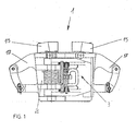
- Fig. 1
- eine Seitenansicht eines Halteelementes;
- Fig. 2
- eine Draufsicht gemäß Fig. 1;
- Fig. 3
- einen Teilschnitt gemäß Linie III-III der Fig. 2 und
- Fig. 4
- eine vergrößerte Detailansicht der Einzelheit IV der Fig. 3.
- Bei der dargestellten Anordnung ist ein Halteelement 1 zur Aufnahme eines nicht näher dargestellten Bohrrohres in Form eines Rohrsegmentes als aufklappbarer Ringkörper dargestellt. Dieser Ringkörper 1 ist durch zwei scharnierartige verschwenkbare Elemente 2 und 3 gebildet, die nach Umhüllung eines Rohrsegmentes verschließbar und verriegelbar sind. Selbstverständlich ist es möglich, das Halteelement als geschlossenen Ringkörper 1 auszubilden und auf ein Rohrsegment über eine zentrale Aufnahmeöffnung 4 aufzunehmen.
- Die Aufnahmeöffnung 4 ist in ihrem Querschnitt über vier Segmente 5 einzustellen, wobei die Segmente 5 als auf das aufgenommene Rohrsegment einwirkende Klemmbacken ausgebildet und vertikal verstellbar sind. Hierzu besitzen die Segmente 5 eine konische Außenkontur 6 und eine korrespondierende Führung 7 im Ringkörper als Halteelement 1.
- Die Segmente 5 sind dabei über eine Führungsstange 8 im Ringkörper 1 gehalten, wobei die Führungsstange 8 über Rippen 9, 10 am Segment 5 und am Ringkörper 1 gehalten sind.
- Oberhalb der Segmente 5 sind pneumatische Stellzylinder 11 angeordnet, die über Leitungen 12 steuerbar sind und die Segmente 5 vertikal nach unten über eine zwischengeschaltete Hülse 13 verstellen sowie eine Verkleinerung der Aufnahmeöffnung 4 über die Konusflächen 6 und 7 herbeiführen und eine Klemmwirkung auf das aufgenommene Rohrsegment ausführen.
- Die Stellzylinder 11 mit der zwischengeschalteten Hülse 13 wirken dabei auf die Rippen 9 der Segmente 5 ein.
- Zur Erhöhung der Rückstellkräfte beim Lösen der Klemmwirkung ist eine spannbare Druckfeder 14 zwischen den Rippen 9, 10 des Segmentes 5 und des Halteringes 1 auf der Führungsstange 8 angeordnet.
- Die Stellzylinder 11 sind dabei über ein Gehäuse 15 am Ringelement 1 festgelegt.
- Die zylindrische Aufnahmefläche der Segmente 5 für die Bohrsegmente wird in dieser Ausführung durch eingesetzte Klemmelemente 16 mit Sägezahnprofil gebildet. Zum Einsetzen und Herausziehen der Bohrrohre ist oberhalb des Ringelementes 1 mit dem aufgenommen Bohrsegment eine Winde angeordnet, die am Ringelement 1 über Elemente 17 als Aufnahme für Schäkel 18 oder dergleichen beidseitig angreifen, wie in Fig. 2 angedeutet ist.
- Hierdurch ist es möglich, das Ringelement 1 entsprechend auf die Rohrsegmente zur Halterung festzusetzen und umzusetzen und über die Winde eine Positionierung des Rohrsegmentes einzustellen, um eine Montage oder Demontage der Verbindungselemente zwischen den Rohrsegmenten durchzuführen.
Claims (6)
- Vorrichtung zur umsetzbaren vertikalen Halterung von Bohrrohren, bestehend aus einer Vielzahl hintereinander angeordneter über Verbindungselemente gekoppelter Rohrsegmente, für einen Einsatz auf Bohrplattformen mit einer lösbaren Halterung am Bohrtisch zum Einsetzen und Herausziehen von Bohrrohren, wobei mit dem Bohrrohr ein Halteelement (1) zum Lösen bzw. Verbinden der Verbindungselemente der Rohrsegmente und Handhabung über Winden verbunden ist und das Halteelement (1) in Form eines Ringkörpers auf das Bohrrohr aufsetzbar ist und im Außenbereich Elemente (17) zum Anschluß an die winde aufweist und der Innenraum (4) des Halteelementes (1) zur Aufnahme des Bohrrohres durch vertikal verstellbare Segmente (5) als Klemmbacken zur Veränderung des Aufnahmedurchmessers mit einem zylindrischen Aufnahmebereich besitzt, dadurch gekennzeichnet, daß die die verstellbaren Segmente (5) eine konische Außenkontur (6) aufweisen und über eine korrespondierende konische Führung (7) im Ringkörper des Halteelementes (1) verschiebbar zur Durchmesserveränderung der Aufnahmeöffnung (4) geführt sind, wobei durch die Vertikalverstellung der Segmente (5) gegenüber dem Ringkörper des Halteelementes (1) mittels oberhalb der Segmente (5) zugeordnete steuerbarer Stellzylinder (11) zur Verengung der Aufnahmeöffnung (4) eine Klemmhalterung des aufgenommenen Bohrrohres einstellbar ist, wobei die Stellzylinder (11) über gebildete Rippen (9) im Außenbereich der Segmente (5) angreifen und die Rippen (9) der Segmente (5) mit korrespondierenden Rippen (10) des Ringkörpers des Halteelementes (1) eine Führungsstange (8) zur Halterung aufnehmen, die eine spannbare Druckfeder (14) zwischen den Rippen (9, 10) führt.
- Vorrichtung nach Anspruch 1, dadurch gekennzeichnet, daß die am Ringkörper des Halteelementes (1) angeordneten Stellzylinder (11) über eine Hülse (13) jeweils auf eine Rippe (9) des Segmentes (5) zur Verstellung einwirkt.
- Vorrichtung nach Anspruch 1, dadurch gekennzeichnet, daß die Stellzylinder (11) für die Verstellung der Segmente (5) durch am Ringkörper (1) angeordnete Druckluftzylinder gebildet sind.
- Vorrichtung nach Anspruch 1 oder 2, dadurch gekennzeichnet, daß die angeordneten Druckluftzylinder (11) als Stellelemente für die Segmente (5) miteinander gekoppelt sind.
- Vorrichtung nach einem der Ansprüche 1 bis 4, dadurch gekennzeichnet, daß die Aufnahmefläche der Segmente (5) für die Bohrrohre durch eingesetzte Klemmelemente (16) mit Kontaktflächen in Form eines Sägezahnprofils aufweisen.
- Vorrichtung nach einem der Ansprüche 1 bis 5, dadurch gekennzeichnet, daß das Halteelement (1) als aufklappbarer und verriegelbarer Ringkörper ausbildet ist.
Priority Applications (1)
| Application Number | Priority Date | Filing Date | Title |
|---|---|---|---|
| PL07015074T PL1892371T3 (pl) | 2006-08-17 | 2007-08-01 | Urządzenie do mocowania rur wiertniczych |
Applications Claiming Priority (1)
| Application Number | Priority Date | Filing Date | Title |
|---|---|---|---|
| DE102006038763A DE102006038763A1 (de) | 2006-08-17 | 2006-08-17 | Vorrichtung zur Halterung von Bohrrohren |
Publications (2)
| Publication Number | Publication Date |
|---|---|
| EP1892371A1 true EP1892371A1 (de) | 2008-02-27 |
| EP1892371B1 EP1892371B1 (de) | 2009-07-08 |
Family
ID=38474232
Family Applications (1)
| Application Number | Title | Priority Date | Filing Date |
|---|---|---|---|
| EP07015074A Not-in-force EP1892371B1 (de) | 2006-08-17 | 2007-08-01 | Vorrichtung zur Halterung von Bohrrohren |
Country Status (6)
| Country | Link |
|---|---|
| US (1) | US20080054662A1 (de) |
| EP (1) | EP1892371B1 (de) |
| AT (1) | ATE435963T1 (de) |
| DE (2) | DE102006038763A1 (de) |
| DK (1) | DK1892371T3 (de) |
| PL (1) | PL1892371T3 (de) |
Cited By (1)
| Publication number | Priority date | Publication date | Assignee | Title |
|---|---|---|---|---|
| CN102094585A (zh) * | 2010-12-14 | 2011-06-15 | 张家港市国锋探矿机械有限公司 | 岩心钻机液压卡盘 |
Families Citing this family (7)
| Publication number | Priority date | Publication date | Assignee | Title |
|---|---|---|---|---|
| US8336937B2 (en) | 2010-11-04 | 2012-12-25 | Robb Farrow | Pipe pile sling |
| US8955620B2 (en) | 2010-12-30 | 2015-02-17 | Longyear Tm, Inc. | Drill rod guide |
| US9140078B2 (en) * | 2011-05-01 | 2015-09-22 | Frank's International, Llc | Extended range single-joint elevator |
| CN102251751B (zh) * | 2011-06-24 | 2013-06-05 | 泰兴石油机械有限公司 | 全自动小鼠洞气动卡盘 |
| CN103552012A (zh) * | 2013-10-17 | 2014-02-05 | 无锡中地地质装备有限公司 | 拧管机用夹持器 |
| CN104612617A (zh) * | 2015-01-22 | 2015-05-13 | 中交二航局第三工程有限公司 | 桩基孔内断钻杆打捞装置 |
| USD936111S1 (en) * | 2019-03-14 | 2021-11-16 | Forum Us, Inc. | Pipe lifting elevator ear |
Citations (2)
| Publication number | Priority date | Publication date | Assignee | Title |
|---|---|---|---|---|
| US5992801A (en) * | 1996-06-26 | 1999-11-30 | Torres; Carlos A. | Pipe gripping assembly and method |
| WO2005106185A1 (en) * | 2004-05-01 | 2005-11-10 | Varco I/P, Inc. | Apparatus and method for handling pipe |
Family Cites Families (9)
| Publication number | Priority date | Publication date | Assignee | Title |
|---|---|---|---|---|
| US1725459A (en) * | 1927-05-05 | 1929-08-20 | Krell | Clamp |
| US2491711A (en) * | 1946-01-14 | 1949-12-20 | Ingram X Calhoun | Hydraulic slip |
| US2889895A (en) * | 1955-12-19 | 1959-06-09 | John E Snow | Pneumatic energy absorber |
| US3358341A (en) * | 1966-05-23 | 1967-12-19 | Byron Jackson Inc | Pipe holding device and slip setting device therefor |
| US4253219A (en) * | 1979-02-14 | 1981-03-03 | Varco International, Inc. | Well slip assembly |
| US4381584A (en) * | 1980-12-15 | 1983-05-03 | Bilco Tools, Inc. | Dual string spider |
| DE4227645C2 (de) * | 1992-08-21 | 1996-10-17 | Weatherford Lamb | Sicherheitsvorrichtung für einen Rohrelevator |
| US5340182A (en) * | 1992-09-04 | 1994-08-23 | Varco International, Inc. | Safety elevator |
| US5791410A (en) * | 1997-01-17 | 1998-08-11 | Frank's Casing Crew & Rental Tools, Inc. | Apparatus and method for improved tubular grip assurance |
-
2006
- 2006-08-17 DE DE102006038763A patent/DE102006038763A1/de not_active Withdrawn
-
2007
- 2007-08-01 PL PL07015074T patent/PL1892371T3/pl unknown
- 2007-08-01 AT AT07015074T patent/ATE435963T1/de not_active IP Right Cessation
- 2007-08-01 EP EP07015074A patent/EP1892371B1/de not_active Not-in-force
- 2007-08-01 DE DE502007001014T patent/DE502007001014D1/de active Active
- 2007-08-01 DK DK07015074T patent/DK1892371T3/da active
- 2007-08-15 US US11/893,381 patent/US20080054662A1/en not_active Abandoned
Patent Citations (2)
| Publication number | Priority date | Publication date | Assignee | Title |
|---|---|---|---|---|
| US5992801A (en) * | 1996-06-26 | 1999-11-30 | Torres; Carlos A. | Pipe gripping assembly and method |
| WO2005106185A1 (en) * | 2004-05-01 | 2005-11-10 | Varco I/P, Inc. | Apparatus and method for handling pipe |
Cited By (1)
| Publication number | Priority date | Publication date | Assignee | Title |
|---|---|---|---|---|
| CN102094585A (zh) * | 2010-12-14 | 2011-06-15 | 张家港市国锋探矿机械有限公司 | 岩心钻机液压卡盘 |
Also Published As
| Publication number | Publication date |
|---|---|
| US20080054662A1 (en) | 2008-03-06 |
| ATE435963T1 (de) | 2009-07-15 |
| DE502007001014D1 (de) | 2009-08-20 |
| EP1892371B1 (de) | 2009-07-08 |
| PL1892371T3 (pl) | 2009-12-31 |
| DE102006038763A1 (de) | 2008-03-20 |
| DK1892371T3 (da) | 2009-10-05 |
Similar Documents
| Publication | Publication Date | Title |
|---|---|---|
| EP1892371B1 (de) | Vorrichtung zur Halterung von Bohrrohren | |
| DE102004062826B4 (de) | Christbaumständer mit am Kraftübertragungselement angreifendem elastischem Element | |
| DE202010012940U1 (de) | Rohr- und Schlauchkupplung | |
| DE102006002293A1 (de) | Vorrichtung zur vertikalen Halterung von Rohren | |
| DE2500859C3 (de) | Hydraulisches Kletterhubwerk | |
| DE2505235C2 (de) | Sattelplatte zur Befestigung von Druckplatten an Rotations-Hochdruckmaschinen | |
| DE102009019998A1 (de) | Entgrater und Verfahren zum Entgraten von Bohrrändern in Gasleitungen | |
| EP2186605B1 (de) | Ausziehkupplung für Einspritzdüsen | |
| DE875329C (de) | Abziehvorrichtung, insbesondere zum Ausziehen und Abziehen von Lagerringen, Zahnkraenzen u. dgl. | |
| DE102020130625A1 (de) | Spannvorrichtung mit Formgedächtnislegierung, Sensor mit einer solchen Spannvorrichtung und Verfahren zum Einspannen eines Bauteils | |
| DE102020005121A1 (de) | Spanneinrichtung zum Positionieren und Spannen von Werkstücken in Innenkonturen, insbesondere Bohrungen | |
| DE102010000283A1 (de) | Vorrichtung und Verfahren zum Herstellen einer Kerze | |
| DE102014101511A1 (de) | Befestigungsvorrichtung insbesondere für ein Spannwerkzeug | |
| DE19740489A1 (de) | Vorrichtung zum Auswechseln bzw. Heben eines in eine Asphaltdecke o.dgl. eingelassenen Rahmens einer Schachtabdeckung | |
| DE10114467B4 (de) | Auszieh- und Eindrückvorrichtung für einen Gasspülstein | |
| DE202012003916U1 (de) | Aufziehvorrichtung für eine Konus-Endabspannklemme | |
| DE102011007826A1 (de) | Vorrichtung zur Sanierung von Rohrleitungen | |
| DE102013003307B4 (de) | Vorrichtung zum Halten eines Schachtkranzes auf einem Schachtelement | |
| DE202015005116U1 (de) | Netzhalterung und Vorrichtung zur Anordnung der Netzhalterung | |
| DE202013104719U1 (de) | Kernbohrständeraufnahme, Kernbohrständer und Kernbohrgerät | |
| DE102010015515A1 (de) | Klemmvorrichtung und Brechvorrichtung mit einer solchen Klemmvorrichtung | |
| EP1426130B1 (de) | Löseeinheit | |
| DE102014101813A1 (de) | Haltevorrichtung für eine Reinigungsvorrichtung an einem Rohr sowie Hochdruckreinigungsvorrichtung zur Reinigung von Rohren | |
| DE202016100577U1 (de) | Probenahmegerät | |
| DE202018101024U1 (de) | Ausrichtvorrichtung für einen Christbaumständer |
Legal Events
| Date | Code | Title | Description |
|---|---|---|---|
| PUAI | Public reference made under article 153(3) epc to a published international application that has entered the european phase |
Free format text: ORIGINAL CODE: 0009012 |
|
| 17P | Request for examination filed |
Effective date: 20071005 |
|
| AK | Designated contracting states |
Kind code of ref document: A1 Designated state(s): AT BE BG CH CY CZ DE DK EE ES FI FR GB GR HU IE IS IT LI LT LU LV MC MT NL PL PT RO SE SI SK TR |
|
| AX | Request for extension of the european patent |
Extension state: AL BA HR MK YU |
|
| AKX | Designation fees paid |
Designated state(s): AT BE BG CH CY CZ DE DK EE ES FI FR GB GR HU IE IS IT LI LT LU LV MC MT NL PL PT RO SE SI SK TR |
|
| GRAP | Despatch of communication of intention to grant a patent |
Free format text: ORIGINAL CODE: EPIDOSNIGR1 |
|
| GRAS | Grant fee paid |
Free format text: ORIGINAL CODE: EPIDOSNIGR3 |
|
| GRAA | (expected) grant |
Free format text: ORIGINAL CODE: 0009210 |
|
| AK | Designated contracting states |
Kind code of ref document: B1 Designated state(s): AT BE BG CH CY CZ DE DK EE ES FI FR GB GR HU IE IS IT LI LT LU LV MC MT NL PL PT RO SE SI SK TR |
|
| REG | Reference to a national code |
Ref country code: GB Ref legal event code: FG4D Free format text: NOT ENGLISH |
|
| REG | Reference to a national code |
Ref country code: CH Ref legal event code: EP |
|
| REG | Reference to a national code |
Ref country code: IE Ref legal event code: FG4D |
|
| REF | Corresponds to: |
Ref document number: 502007001014 Country of ref document: DE Date of ref document: 20090820 Kind code of ref document: P |
|
| REG | Reference to a national code |
Ref country code: DK Ref legal event code: T3 |
|
| PG25 | Lapsed in a contracting state [announced via postgrant information from national office to epo] |
Ref country code: SI Free format text: LAPSE BECAUSE OF FAILURE TO SUBMIT A TRANSLATION OF THE DESCRIPTION OR TO PAY THE FEE WITHIN THE PRESCRIBED TIME-LIMIT Effective date: 20090708 |
|
| NLV1 | Nl: lapsed or annulled due to failure to fulfill the requirements of art. 29p and 29m of the patents act | ||
| REG | Reference to a national code |
Ref country code: PL Ref legal event code: T3 |
|
| PG25 | Lapsed in a contracting state [announced via postgrant information from national office to epo] |
Ref country code: ES Free format text: LAPSE BECAUSE OF FAILURE TO SUBMIT A TRANSLATION OF THE DESCRIPTION OR TO PAY THE FEE WITHIN THE PRESCRIBED TIME-LIMIT Effective date: 20091019 Ref country code: FI Free format text: LAPSE BECAUSE OF FAILURE TO SUBMIT A TRANSLATION OF THE DESCRIPTION OR TO PAY THE FEE WITHIN THE PRESCRIBED TIME-LIMIT Effective date: 20090708 Ref country code: IS Free format text: LAPSE BECAUSE OF FAILURE TO SUBMIT A TRANSLATION OF THE DESCRIPTION OR TO PAY THE FEE WITHIN THE PRESCRIBED TIME-LIMIT Effective date: 20091108 Ref country code: LT Free format text: LAPSE BECAUSE OF FAILURE TO SUBMIT A TRANSLATION OF THE DESCRIPTION OR TO PAY THE FEE WITHIN THE PRESCRIBED TIME-LIMIT Effective date: 20090708 |
|
| REG | Reference to a national code |
Ref country code: IE Ref legal event code: FD4D |
|
| PG25 | Lapsed in a contracting state [announced via postgrant information from national office to epo] |
Ref country code: NL Free format text: LAPSE BECAUSE OF FAILURE TO SUBMIT A TRANSLATION OF THE DESCRIPTION OR TO PAY THE FEE WITHIN THE PRESCRIBED TIME-LIMIT Effective date: 20090708 Ref country code: LV Free format text: LAPSE BECAUSE OF FAILURE TO SUBMIT A TRANSLATION OF THE DESCRIPTION OR TO PAY THE FEE WITHIN THE PRESCRIBED TIME-LIMIT Effective date: 20090708 |
|
| BERE | Be: lapsed |
Owner name: BLOHM + VOSS REPAIR G.M.B.H. Effective date: 20090831 |
|
| PG25 | Lapsed in a contracting state [announced via postgrant information from national office to epo] |
Ref country code: PT Free format text: LAPSE BECAUSE OF FAILURE TO SUBMIT A TRANSLATION OF THE DESCRIPTION OR TO PAY THE FEE WITHIN THE PRESCRIBED TIME-LIMIT Effective date: 20091109 Ref country code: MC Free format text: LAPSE BECAUSE OF NON-PAYMENT OF DUE FEES Effective date: 20090831 Ref country code: BG Free format text: LAPSE BECAUSE OF FAILURE TO SUBMIT A TRANSLATION OF THE DESCRIPTION OR TO PAY THE FEE WITHIN THE PRESCRIBED TIME-LIMIT Effective date: 20091008 |
|
| PG25 | Lapsed in a contracting state [announced via postgrant information from national office to epo] |
Ref country code: RO Free format text: LAPSE BECAUSE OF FAILURE TO SUBMIT A TRANSLATION OF THE DESCRIPTION OR TO PAY THE FEE WITHIN THE PRESCRIBED TIME-LIMIT Effective date: 20090708 Ref country code: IE Free format text: LAPSE BECAUSE OF FAILURE TO SUBMIT A TRANSLATION OF THE DESCRIPTION OR TO PAY THE FEE WITHIN THE PRESCRIBED TIME-LIMIT Effective date: 20090708 Ref country code: EE Free format text: LAPSE BECAUSE OF FAILURE TO SUBMIT A TRANSLATION OF THE DESCRIPTION OR TO PAY THE FEE WITHIN THE PRESCRIBED TIME-LIMIT Effective date: 20090708 |
|
| PLBE | No opposition filed within time limit |
Free format text: ORIGINAL CODE: 0009261 |
|
| STAA | Information on the status of an ep patent application or granted ep patent |
Free format text: STATUS: NO OPPOSITION FILED WITHIN TIME LIMIT |
|
| REG | Reference to a national code |
Ref country code: FR Ref legal event code: ST Effective date: 20100430 |
|
| PG25 | Lapsed in a contracting state [announced via postgrant information from national office to epo] |
Ref country code: SK Free format text: LAPSE BECAUSE OF FAILURE TO SUBMIT A TRANSLATION OF THE DESCRIPTION OR TO PAY THE FEE WITHIN THE PRESCRIBED TIME-LIMIT Effective date: 20090708 |
|
| 26N | No opposition filed |
Effective date: 20100409 |
|
| PG25 | Lapsed in a contracting state [announced via postgrant information from national office to epo] |
Ref country code: BE Free format text: LAPSE BECAUSE OF NON-PAYMENT OF DUE FEES Effective date: 20090831 |
|
| PG25 | Lapsed in a contracting state [announced via postgrant information from national office to epo] |
Ref country code: FR Free format text: LAPSE BECAUSE OF NON-PAYMENT OF DUE FEES Effective date: 20090908 |
|
| PG25 | Lapsed in a contracting state [announced via postgrant information from national office to epo] |
Ref country code: GR Free format text: LAPSE BECAUSE OF FAILURE TO SUBMIT A TRANSLATION OF THE DESCRIPTION OR TO PAY THE FEE WITHIN THE PRESCRIBED TIME-LIMIT Effective date: 20091009 |
|
| PG25 | Lapsed in a contracting state [announced via postgrant information from national office to epo] |
Ref country code: AT Free format text: LAPSE BECAUSE OF NON-PAYMENT OF DUE FEES Effective date: 20090801 |
|
| PGFP | Annual fee paid to national office [announced via postgrant information from national office to epo] |
Ref country code: CZ Payment date: 20100730 Year of fee payment: 4 Ref country code: DE Payment date: 20100823 Year of fee payment: 4 |
|
| PGFP | Annual fee paid to national office [announced via postgrant information from national office to epo] |
Ref country code: PL Payment date: 20100726 Year of fee payment: 4 |
|
| PGFP | Annual fee paid to national office [announced via postgrant information from national office to epo] |
Ref country code: DK Payment date: 20100810 Year of fee payment: 4 |
|
| PG25 | Lapsed in a contracting state [announced via postgrant information from national office to epo] |
Ref country code: LU Free format text: LAPSE BECAUSE OF NON-PAYMENT OF DUE FEES Effective date: 20090801 Ref country code: MT Free format text: LAPSE BECAUSE OF FAILURE TO SUBMIT A TRANSLATION OF THE DESCRIPTION OR TO PAY THE FEE WITHIN THE PRESCRIBED TIME-LIMIT Effective date: 20090708 |
|
| PG25 | Lapsed in a contracting state [announced via postgrant information from national office to epo] |
Ref country code: HU Free format text: LAPSE BECAUSE OF FAILURE TO SUBMIT A TRANSLATION OF THE DESCRIPTION OR TO PAY THE FEE WITHIN THE PRESCRIBED TIME-LIMIT Effective date: 20100109 |
|
| PG25 | Lapsed in a contracting state [announced via postgrant information from national office to epo] |
Ref country code: TR Free format text: LAPSE BECAUSE OF FAILURE TO SUBMIT A TRANSLATION OF THE DESCRIPTION OR TO PAY THE FEE WITHIN THE PRESCRIBED TIME-LIMIT Effective date: 20090708 |
|
| PG25 | Lapsed in a contracting state [announced via postgrant information from national office to epo] |
Ref country code: CY Free format text: LAPSE BECAUSE OF FAILURE TO SUBMIT A TRANSLATION OF THE DESCRIPTION OR TO PAY THE FEE WITHIN THE PRESCRIBED TIME-LIMIT Effective date: 20090708 |
|
| PGFP | Annual fee paid to national office [announced via postgrant information from national office to epo] |
Ref country code: IT Payment date: 20100831 Year of fee payment: 4 |
|
| REG | Reference to a national code |
Ref country code: CH Ref legal event code: PL |
|
| GBPC | Gb: european patent ceased through non-payment of renewal fee |
Effective date: 20110801 |
|
| PG25 | Lapsed in a contracting state [announced via postgrant information from national office to epo] |
Ref country code: LI Free format text: LAPSE BECAUSE OF NON-PAYMENT OF DUE FEES Effective date: 20110831 Ref country code: CZ Free format text: LAPSE BECAUSE OF NON-PAYMENT OF DUE FEES Effective date: 20110801 Ref country code: CH Free format text: LAPSE BECAUSE OF NON-PAYMENT OF DUE FEES Effective date: 20110831 |
|
| REG | Reference to a national code |
Ref country code: DK Ref legal event code: EBP |
|
| PG25 | Lapsed in a contracting state [announced via postgrant information from national office to epo] |
Ref country code: IT Free format text: LAPSE BECAUSE OF NON-PAYMENT OF DUE FEES Effective date: 20110801 |
|
| REG | Reference to a national code |
Ref country code: DE Ref legal event code: R119 Ref document number: 502007001014 Country of ref document: DE Effective date: 20120301 |
|
| PG25 | Lapsed in a contracting state [announced via postgrant information from national office to epo] |
Ref country code: DK Free format text: LAPSE BECAUSE OF NON-PAYMENT OF DUE FEES Effective date: 20110831 |
|
| PG25 | Lapsed in a contracting state [announced via postgrant information from national office to epo] |
Ref country code: GB Free format text: LAPSE BECAUSE OF NON-PAYMENT OF DUE FEES Effective date: 20110801 |
|
| PG25 | Lapsed in a contracting state [announced via postgrant information from national office to epo] |
Ref country code: SE Free format text: LAPSE BECAUSE OF FAILURE TO SUBMIT A TRANSLATION OF THE DESCRIPTION OR TO PAY THE FEE WITHIN THE PRESCRIBED TIME-LIMIT Effective date: 20090708 |
|
| PG25 | Lapsed in a contracting state [announced via postgrant information from national office to epo] |
Ref country code: PL Free format text: LAPSE BECAUSE OF NON-PAYMENT OF DUE FEES Effective date: 20110801 |
|
| REG | Reference to a national code |
Ref country code: PL Ref legal event code: LAPE |
|
| PG25 | Lapsed in a contracting state [announced via postgrant information from national office to epo] |
Ref country code: DE Free format text: LAPSE BECAUSE OF NON-PAYMENT OF DUE FEES Effective date: 20120301 |