EP1892394B1 - Système de traitement postérieur de gaz d'échappement - Google Patents
Système de traitement postérieur de gaz d'échappement Download PDFInfo
- Publication number
- EP1892394B1 EP1892394B1 EP07013161A EP07013161A EP1892394B1 EP 1892394 B1 EP1892394 B1 EP 1892394B1 EP 07013161 A EP07013161 A EP 07013161A EP 07013161 A EP07013161 A EP 07013161A EP 1892394 B1 EP1892394 B1 EP 1892394B1
- Authority
- EP
- European Patent Office
- Prior art keywords
- exhaust
- aftertreatment system
- catalyst
- nitrogen
- particle
- Prior art date
- Legal status (The legal status is an assumption and is not a legal conclusion. Google has not performed a legal analysis and makes no representation as to the accuracy of the status listed.)
- Active
Links
Images

Classifications
-
- F—MECHANICAL ENGINEERING; LIGHTING; HEATING; WEAPONS; BLASTING
- F01—MACHINES OR ENGINES IN GENERAL; ENGINE PLANTS IN GENERAL; STEAM ENGINES
- F01N—GAS-FLOW SILENCERS OR EXHAUST APPARATUS FOR MACHINES OR ENGINES IN GENERAL; GAS-FLOW SILENCERS OR EXHAUST APPARATUS FOR INTERNAL-COMBUSTION ENGINES
- F01N3/00—Exhaust or silencing apparatus having means for purifying, rendering innocuous, or otherwise treating exhaust
- F01N3/08—Exhaust or silencing apparatus having means for purifying, rendering innocuous, or otherwise treating exhaust for rendering innocuous
- F01N3/10—Exhaust or silencing apparatus having means for purifying, rendering innocuous, or otherwise treating exhaust for rendering innocuous by thermal or catalytic conversion of noxious components of exhaust
- F01N3/18—Exhaust or silencing apparatus having means for purifying, rendering innocuous, or otherwise treating exhaust for rendering innocuous by thermal or catalytic conversion of noxious components of exhaust characterised by methods of operation; Control
- F01N3/20—Exhaust or silencing apparatus having means for purifying, rendering innocuous, or otherwise treating exhaust for rendering innocuous by thermal or catalytic conversion of noxious components of exhaust characterised by methods of operation; Control specially adapted for catalytic conversion
- F01N3/206—Adding periodically or continuously substances to exhaust gases for promoting purification, e.g. catalytic material in liquid form, NOx reducing agents
- F01N3/2066—Selective catalytic reduction [SCR]
-
- F—MECHANICAL ENGINEERING; LIGHTING; HEATING; WEAPONS; BLASTING
- F01—MACHINES OR ENGINES IN GENERAL; ENGINE PLANTS IN GENERAL; STEAM ENGINES
- F01N—GAS-FLOW SILENCERS OR EXHAUST APPARATUS FOR MACHINES OR ENGINES IN GENERAL; GAS-FLOW SILENCERS OR EXHAUST APPARATUS FOR INTERNAL-COMBUSTION ENGINES
- F01N13/00—Exhaust or silencing apparatus characterised by constructional features
- F01N13/009—Exhaust or silencing apparatus characterised by constructional features having two or more separate purifying devices arranged in series
-
- F—MECHANICAL ENGINEERING; LIGHTING; HEATING; WEAPONS; BLASTING
- F01—MACHINES OR ENGINES IN GENERAL; ENGINE PLANTS IN GENERAL; STEAM ENGINES
- F01N—GAS-FLOW SILENCERS OR EXHAUST APPARATUS FOR MACHINES OR ENGINES IN GENERAL; GAS-FLOW SILENCERS OR EXHAUST APPARATUS FOR INTERNAL-COMBUSTION ENGINES
- F01N13/00—Exhaust or silencing apparatus characterised by constructional features
- F01N13/011—Exhaust or silencing apparatus characterised by constructional features having two or more purifying devices arranged in parallel
-
- F—MECHANICAL ENGINEERING; LIGHTING; HEATING; WEAPONS; BLASTING
- F01—MACHINES OR ENGINES IN GENERAL; ENGINE PLANTS IN GENERAL; STEAM ENGINES
- F01N—GAS-FLOW SILENCERS OR EXHAUST APPARATUS FOR MACHINES OR ENGINES IN GENERAL; GAS-FLOW SILENCERS OR EXHAUST APPARATUS FOR INTERNAL-COMBUSTION ENGINES
- F01N3/00—Exhaust or silencing apparatus having means for purifying, rendering innocuous, or otherwise treating exhaust
- F01N3/02—Exhaust or silencing apparatus having means for purifying, rendering innocuous, or otherwise treating exhaust for cooling, or for removing solid constituents of, exhaust
- F01N3/021—Exhaust or silencing apparatus having means for purifying, rendering innocuous, or otherwise treating exhaust for cooling, or for removing solid constituents of, exhaust by means of filters
-
- F—MECHANICAL ENGINEERING; LIGHTING; HEATING; WEAPONS; BLASTING
- F01—MACHINES OR ENGINES IN GENERAL; ENGINE PLANTS IN GENERAL; STEAM ENGINES
- F01N—GAS-FLOW SILENCERS OR EXHAUST APPARATUS FOR MACHINES OR ENGINES IN GENERAL; GAS-FLOW SILENCERS OR EXHAUST APPARATUS FOR INTERNAL-COMBUSTION ENGINES
- F01N3/00—Exhaust or silencing apparatus having means for purifying, rendering innocuous, or otherwise treating exhaust
- F01N3/02—Exhaust or silencing apparatus having means for purifying, rendering innocuous, or otherwise treating exhaust for cooling, or for removing solid constituents of, exhaust
- F01N3/037—Exhaust or silencing apparatus having means for purifying, rendering innocuous, or otherwise treating exhaust for cooling, or for removing solid constituents of, exhaust by means of inertial or centrifugal separators, e.g. of cyclone type, optionally combined or associated with agglomerators
-
- F—MECHANICAL ENGINEERING; LIGHTING; HEATING; WEAPONS; BLASTING
- F01—MACHINES OR ENGINES IN GENERAL; ENGINE PLANTS IN GENERAL; STEAM ENGINES
- F01N—GAS-FLOW SILENCERS OR EXHAUST APPARATUS FOR MACHINES OR ENGINES IN GENERAL; GAS-FLOW SILENCERS OR EXHAUST APPARATUS FOR INTERNAL-COMBUSTION ENGINES
- F01N3/00—Exhaust or silencing apparatus having means for purifying, rendering innocuous, or otherwise treating exhaust
- F01N3/08—Exhaust or silencing apparatus having means for purifying, rendering innocuous, or otherwise treating exhaust for rendering innocuous
- F01N3/10—Exhaust or silencing apparatus having means for purifying, rendering innocuous, or otherwise treating exhaust for rendering innocuous by thermal or catalytic conversion of noxious components of exhaust
- F01N3/18—Exhaust or silencing apparatus having means for purifying, rendering innocuous, or otherwise treating exhaust for rendering innocuous by thermal or catalytic conversion of noxious components of exhaust characterised by methods of operation; Control
- F01N3/20—Exhaust or silencing apparatus having means for purifying, rendering innocuous, or otherwise treating exhaust for rendering innocuous by thermal or catalytic conversion of noxious components of exhaust characterised by methods of operation; Control specially adapted for catalytic conversion
- F01N3/2053—By-passing catalytic reactors, e.g. to prevent overheating
-
- F—MECHANICAL ENGINEERING; LIGHTING; HEATING; WEAPONS; BLASTING
- F02—COMBUSTION ENGINES; HOT-GAS OR COMBUSTION-PRODUCT ENGINE PLANTS
- F02M—SUPPLYING COMBUSTION ENGINES IN GENERAL WITH COMBUSTIBLE MIXTURES OR CONSTITUENTS THEREOF
- F02M26/00—Engine-pertinent apparatus for adding exhaust gases to combustion-air, main fuel or fuel-air mixture, e.g. by exhaust gas recirculation [EGR] systems
- F02M26/52—Systems for actuating EGR valves
- F02M26/55—Systems for actuating EGR valves using vacuum actuators
- F02M26/56—Systems for actuating EGR valves using vacuum actuators having pressure modulation valves
- F02M26/57—Systems for actuating EGR valves using vacuum actuators having pressure modulation valves using electronic means, e.g. electromagnetic valves
-
- F—MECHANICAL ENGINEERING; LIGHTING; HEATING; WEAPONS; BLASTING
- F01—MACHINES OR ENGINES IN GENERAL; ENGINE PLANTS IN GENERAL; STEAM ENGINES
- F01N—GAS-FLOW SILENCERS OR EXHAUST APPARATUS FOR MACHINES OR ENGINES IN GENERAL; GAS-FLOW SILENCERS OR EXHAUST APPARATUS FOR INTERNAL-COMBUSTION ENGINES
- F01N2240/00—Combination or association of two or more different exhaust treating devices, or of at least one such device with an auxiliary device, not covered by indexing codes F01N2230/00 or F01N2250/00, one of the devices being
- F01N2240/40—Combination or association of two or more different exhaust treating devices, or of at least one such device with an auxiliary device, not covered by indexing codes F01N2230/00 or F01N2250/00, one of the devices being a hydrolysis catalyst
-
- F—MECHANICAL ENGINEERING; LIGHTING; HEATING; WEAPONS; BLASTING
- F01—MACHINES OR ENGINES IN GENERAL; ENGINE PLANTS IN GENERAL; STEAM ENGINES
- F01N—GAS-FLOW SILENCERS OR EXHAUST APPARATUS FOR MACHINES OR ENGINES IN GENERAL; GAS-FLOW SILENCERS OR EXHAUST APPARATUS FOR INTERNAL-COMBUSTION ENGINES
- F01N2430/00—Influencing exhaust purification, e.g. starting of catalytic reaction, filter regeneration, or the like, by controlling engine operating characteristics
-
- F—MECHANICAL ENGINEERING; LIGHTING; HEATING; WEAPONS; BLASTING
- F01—MACHINES OR ENGINES IN GENERAL; ENGINE PLANTS IN GENERAL; STEAM ENGINES
- F01N—GAS-FLOW SILENCERS OR EXHAUST APPARATUS FOR MACHINES OR ENGINES IN GENERAL; GAS-FLOW SILENCERS OR EXHAUST APPARATUS FOR INTERNAL-COMBUSTION ENGINES
- F01N2570/00—Exhaust treating apparatus eliminating, absorbing or adsorbing specific elements or compounds
- F01N2570/14—Nitrogen oxides
-
- F—MECHANICAL ENGINEERING; LIGHTING; HEATING; WEAPONS; BLASTING
- F01—MACHINES OR ENGINES IN GENERAL; ENGINE PLANTS IN GENERAL; STEAM ENGINES
- F01N—GAS-FLOW SILENCERS OR EXHAUST APPARATUS FOR MACHINES OR ENGINES IN GENERAL; GAS-FLOW SILENCERS OR EXHAUST APPARATUS FOR INTERNAL-COMBUSTION ENGINES
- F01N2610/00—Adding substances to exhaust gases
- F01N2610/02—Adding substances to exhaust gases the substance being ammonia or urea
-
- F—MECHANICAL ENGINEERING; LIGHTING; HEATING; WEAPONS; BLASTING
- F01—MACHINES OR ENGINES IN GENERAL; ENGINE PLANTS IN GENERAL; STEAM ENGINES
- F01N—GAS-FLOW SILENCERS OR EXHAUST APPARATUS FOR MACHINES OR ENGINES IN GENERAL; GAS-FLOW SILENCERS OR EXHAUST APPARATUS FOR INTERNAL-COMBUSTION ENGINES
- F01N2610/00—Adding substances to exhaust gases
- F01N2610/05—Adding substances to exhaust gases the substance being carbon monoxide
-
- F—MECHANICAL ENGINEERING; LIGHTING; HEATING; WEAPONS; BLASTING
- F02—COMBUSTION ENGINES; HOT-GAS OR COMBUSTION-PRODUCT ENGINE PLANTS
- F02B—INTERNAL-COMBUSTION PISTON ENGINES; COMBUSTION ENGINES IN GENERAL
- F02B37/00—Engines characterised by provision of pumps driven at least for part of the time by exhaust
-
- Y—GENERAL TAGGING OF NEW TECHNOLOGICAL DEVELOPMENTS; GENERAL TAGGING OF CROSS-SECTIONAL TECHNOLOGIES SPANNING OVER SEVERAL SECTIONS OF THE IPC; TECHNICAL SUBJECTS COVERED BY FORMER USPC CROSS-REFERENCE ART COLLECTIONS [XRACs] AND DIGESTS
- Y02—TECHNOLOGIES OR APPLICATIONS FOR MITIGATION OR ADAPTATION AGAINST CLIMATE CHANGE
- Y02A—TECHNOLOGIES FOR ADAPTATION TO CLIMATE CHANGE
- Y02A50/00—TECHNOLOGIES FOR ADAPTATION TO CLIMATE CHANGE in human health protection, e.g. against extreme weather
- Y02A50/20—Air quality improvement or preservation, e.g. vehicle emission control or emission reduction by using catalytic converters
-
- Y—GENERAL TAGGING OF NEW TECHNOLOGICAL DEVELOPMENTS; GENERAL TAGGING OF CROSS-SECTIONAL TECHNOLOGIES SPANNING OVER SEVERAL SECTIONS OF THE IPC; TECHNICAL SUBJECTS COVERED BY FORMER USPC CROSS-REFERENCE ART COLLECTIONS [XRACs] AND DIGESTS
- Y02—TECHNOLOGIES OR APPLICATIONS FOR MITIGATION OR ADAPTATION AGAINST CLIMATE CHANGE
- Y02T—CLIMATE CHANGE MITIGATION TECHNOLOGIES RELATED TO TRANSPORTATION
- Y02T10/00—Road transport of goods or passengers
- Y02T10/10—Internal combustion engine [ICE] based vehicles
- Y02T10/12—Improving ICE efficiencies
Definitions
- the invention relates to an exhaust aftertreatment system in operated with excess air internal combustion engines, such as diesel engines and gasoline engines with direct injection.
- nitrogen oxides are among the limited exhaust gas components that arise during combustion processes and whose permissible emissions are being lowered even further.
- different methods are used today.
- the reduction of nitrogen oxides is usually done with the aid of catalysts, in oxygen-rich exhaust gas, a reducing agent is also required in order to increase the selectivity and NO x conversions.
- SCR method where SCR stands for "selective catalytic reduction". They have been used for many years in power plants and, more recently, in internal combustion engines. A detailed description of such methods is the DE 34 28 232 A1 refer to.
- V 2 O 5 -containing mixed oxides for example in the form V 2 O 5 / WO 3 / TiO 2 , can be used. Typical V 2 O 5 contents are between 0.2-3%.
- reducing agents ammonia or ammonia releasing compounds, such as urea or ammonium formate, in solid or solution form are used in practical application.
- One mole of ammonia is necessary for the reaction of one mole of nitrogen monoxide. 4NO + 4NH 3 + O 2 ⁇ 4N 2 + 6H 2 O (1)
- particle separators or particulate filters are used both in power plants and in vehicles.
- a typical arrangement for use in vehicles with Prismabscheider is for example in the EP 1 072 765 A1 described.
- Such arrangements differ from those with particle filters in that the diameter of the channels of the particle separator is substantially larger than the diameter of the largest occurring particles while in particle filters the diameter of the filter channels is in the range of the diameter of the particles.
- particulate filters are prone to clogging, increasing exhaust backpressure and reducing engine performance.
- An arrangement and a method with particle filter is the EP 0 341 832 A2 refer to.
- the two aforementioned arrangements and methods are distinguished by the fact that the oxidation catalyst arranged upstream of the particle separator or particle filter-usually a catalyst with platinum as active material-contains the nitrogen monoxide in the exhaust gas with the aid of the likewise contained residual oxygen to nitrogen dioxide oxidized, which in turn in the particle separator, or particle filter with the carbon particles to CO, CO 2 , N 2 and NO.
- the oxidation catalyst arranged upstream of the particle separator or particle filter usually a catalyst with platinum as active material-contains the nitrogen monoxide in the exhaust gas with the aid of the likewise contained residual oxygen to nitrogen dioxide oxidized, which in turn in the particle separator, or particle filter with the carbon particles to CO, CO 2 , N 2 and NO.
- an arrangement which consists of an oxidation catalyst downstream of this arranged in the exhaust gas flow SCR catalyst and in turn arranged downstream of this in the exhaust gas flow particle filter.
- the supply of the reducing agent for the selective catalytic reaction taking place in the SCR catalytic converter takes place immediately upstream of the SCR catalytic converter via a urea injection device controlled as a function of operating parameters of the internal combustion engine.
- a disadvantage of this arrangement is that the nitrogen dioxide generated in the oxidation catalyst is substantially completely consumed by the selective catalytic reduction in the SCR catalyst, that is, is not available for the implementation of the deposited in the downstream particulate filter fines.
- the regeneration of the particulate filter must therefore be accomplished consuming by cyclically heating the exhaust stream by the exhaust gas stream is enriched with unburned hydrocarbons. This is done either by enriching the combustion mixture or injecting fuel before the particulate filter.
- Such an arrangement for regenerating the particulate filter is on the one hand laborious and therefore expensive, on the other hand, the cyclic regeneration of the particle filter located at the end of the arrangement again generates pollutants which can no longer be removed from the exhaust gas.
- the use of particulate filters can cause blockage of the filters by oil ash, so that they have to be removed and cleaned at certain intervals.
- Another combination of a particle filter and a selective arrangement catalytic reduction is from the EP 1 054 722 A1 known.
- the arrangement described therein consists of an oxidation catalyst arranged in the exhaust gas stream which increases the proportion of nitrogen dioxide in the exhaust gas, downstream a fine filter, a reservoir for the reducing liquid, and an injection device for the reducing liquid, which is arranged behind the fine filter and a downstream in the exhaust gas flow arranged SCR catalyst.
- the arrangement described above allows a continuous reaction of deposited in the fines filter fines particles of carbon black type with the help of the nitrogen dioxide produced in the oxidation catalyst, but has another serious disadvantage.
- the particulate filter causes a cooling of the exhaust gas, so that z. B.
- hydrolysis ie the catalytic decomposition of isocyanic acid (HNCO) into ammonia (NH 3 ) and carbon dioxide (CO 2 ),
- the exhaust aftertreatment system provides an oxidation catalyst in the exhaust gas stream of the internal combustion engine, which converts at least part of the nitrogen monoxide contained in the exhaust gas stream into nitrogen dioxide.
- an ammonia-releasing reactant must be fed into an exhaust gas stream branched off from the exhaust stream upstream of the oxidation catalyst and recycled into the exhaust stream downstream of the oxidation catalyst, to pass the reducing agent downstream of the injection site through the still hot exhaust gas Split off ammonia (NH 3 ), wherein upstream of the oxidation catalyst at least one turbine of at least one exhaust gas turbocharger is arranged and the branch of the exhaust gas partial stream is fed into the reducing agent, upstream of the turbine of the exhaust gas turbocharger.
- the supply of the reducing agent is thus close to the engine and even before the particle or particulate filter whereby a cooling of the exhaust stream is avoided in an advantageous manner.
- the particle separator or particle filter is arranged downstream of the oxidation catalyst in the exhaust gas stream, it is possible to continuously convert the accumulated soot particles into carbon monoxide, carbon dioxide, nitrogen and nitrogen monoxide with the aid of the nitrogen dioxide contained in the exhaust gas stream, so that advantageously a special cyclic regeneration of the particle separator or particulate filter can be dispensed with.
- the reduction of the remaining nitrogen oxides in the exhaust gas to nitrogen and water vapor is advantageously carried out by the downstream downstream SCR system.
- hydrolysis catalytic converter between the feed point and the particle separator or particle filter.
- hydrolysis catalyst and particle separator or particle filter advantageously minimizing the size, can be combined in one component by at least partially coating or impregnating the particle separator or particle filter with an active component forming the hydrolysis catalyst.
- the branch of the exhaust-gas partial stream into which the reducing fluid is injected upstream to the turbine of the exhaust-gas turbocharger in order to achieve the highest possible temperature level for the elimination of the ammonia. If it is a twin-flow turbine, wherein the one flood is fed by at least one first cylinder and the other flood of at least one second cylinder with exhaust gas, it is advantageous to the exhaust gas partial stream of to divert one of the two floods.
- the cylinders of the tide, from which the partial exhaust gas stream branches off, can then be operated with different engine parameters than the cylinders of the other tide, so that an optimization of the conditions in the exhaust gas partial stream with regard to the preparation of the reducing agent is advantageously possible by, for example, the exhaust gas temperature in the starting phase or in low load range is raised.
- the turbine of one exhaust gas turbocharger from a first cylinder bank of the internal combustion engine and the turbine of the other exhaust gas turbocharger from a second cylinder bank of the internal combustion engine is charged with exhaust gas
- the partial exhaust gas flow upstream of the turbine the two exhaust gas turbochargers branches off the exhaust gas flow.
- the cylinders of the cylinder bank, from whose exhaust tract the exhaust partial flow branches off, can then be operated with different engine parameters than the cylinders of the other cylinder bank.
- the exhaust gas temperature is raised in the starting phase or in the low load range.
- a throttle element in the exhaust gas partial flow, which controls the space velocity of the exhaust gas and / or the amount of exhaust gas in the branch.
- the catalyst for the oxidation of NO to NO 2 and for the catalyst for the oxidation of Ammonia can be advantageously used platinum and / or palladium and / or iridium and / or their oxides and / or IrTiOx and / or zeolites as active material.
- the SCR catalysts for the reduction of nitrogen oxides with the aid of ammonia can advantageously contain as active component vanadium and / or vanadium pentoxide and / or titanium dioxide and / or tungsten oxide and / or copper-containing zeolites and / or iron-containing zeolites and / or cobalt-containing zeolites.
- Suitable active components for the hydrolysis catalyst for the release of Ammniak are titanium dioxide and / or silicon dioxide and / or aluminum oxide and / or zeolites.
- the catalysts mentioned above may be solid catalysts and / or coating catalysts, the active components of the catalysts may be applied to ceramic and / or metallic and / or silicate-containing and / or quartz-containing supports.
- the exhaust-gas temperature at the particle separator or particle filter as well as the content of nitrogen dioxide at the particle separator or particle filter significantly influences the effectiveness of the exhaust-gas aftertreatment system
- the engine parameters or by introducing hydrocarbons into the exhaust stream upstream of the oxidation catalyst for oxidizing nitrogen monoxide (and / or hydrocarbon and / or carbon monoxide) the exhaust temperature and nitrogen dioxide content may be increased.
- FIG Fig. 1 An arrangement for the selective catalytic reduction and reduction of solid particles in the exhaust gas of an internal combustion engine is shown schematically in FIG Fig. 1 shown.
- the reducing agent as is the case in motor vehicles with SCR catalyst in practice, is an aqueous urea solution, but of course the addition of urea in solid form is also conceivable, as already described in detail in the relevant specialist literature.
- ammonia as a reducing agent, which is obtained elsewhere, for example under more favorable thermal conditions, from a substance which releases ammonia.
- the metering takes place as a function of operating parameters of the internal combustion engine, controlled by a motor control unit (not shown), in such a way that the aqueous urea solution is sprayed into the exhaust gas flow via a nozzle 2 immediately before a hydrolysis catalytic converter 3.
- the task of the hydrolysis catalyst 3 is to convert the aqueous urea solution as completely as possible into ammonia and water vapor while avoiding by-products. Under certain conditions, this splitting takes place sufficiently without hydrolysis catalyst, so that it can then be omitted.
- an oxidation catalyst 4 is arranged, whose task is to oxidize according to the above-mentioned reaction (2) a portion of the nitrogen monoxide contained in the exhaust gas by means of excess oxygen present in the exhaust gas to nitrogen dioxide.
- the nitrogen dioxide thus produced is used on the one hand in the reduction of the solid particles and on the other hand in the downstream SCR reaction, as described in more detail below.
- a particle separator Downstream of the hydrolysis catalytic converter 3 and the oxidation catalytic converter 4 arranged parallel thereto, a particle separator is arranged, which accumulates the soot particles present in the exhaust gas.
- the soot particles retained in the particle separator 5 are continuously converted into carbon monoxide, carbon dioxide, nitrogen and nitrogen monoxide by the nitrogen dioxide generated upstream with the aid of the oxidation catalyst 4, so that costly regeneration cycles for the particle separator 5 are eliminated.
- the actual selective catalytic reduction of the nitrogen oxides takes place in the SCR catalyst downstream of the particle separator, which is intended to transfer the largest possible proportion of the nitrogen oxides (NO X ) present in the exhaust gas with simultaneous high selectivity of the reduction into nitrogen and water vapor, without any excess ammonia (NH 3 ) remains in the exhaust stream.
- NO X nitrogen oxides
- NH 3 ammonia
- the residual nitrogen dioxide possibly still present in the exhaust gas stream is more reactive than the remaining NO contained in the exhaust gas, it is therefore desirable to design the oxidation catalyst so that the highest possible proportion of nitrogen monoxide is converted into nitrogen dioxide, so more if possible as is necessary to implement the soot particles in the particle separator.
- V 2 O 5 -free SCR catalysts which are usually based on iron, cobalt or copper zeolite material, may be useful.
- the hydrolysis catalytic converter 3 can be dispensed with.
- the difference between particle separator and particle filter has already been carried out.
- the interchangeability of particle separator and particle filter also applies to the examples described below without being explicitly referred to again.
- FIG. 2 One opposite to the example FIG. 1 simplified embodiment shows the example Fig. 2 ,
- a parallel guidance of the exhaust gas flow which is also indicated in this example by arrows, is dispensed with, so that the exhaust point for the reducing agent downstream of an arranged in the exhaust stream oxidation catalyst 4 ', which converts a portion of the nitrogen monoxide contained in the exhaust stream into nitrogen dioxide followed.
- the supply of the reducing agent, in this example aqueous urea solution (AdBlue) is effected by a depending on operating parameters of the internal combustion engine metering device 9, which removes the aqueous urea solution from a reservoir and a nozzle 2 ', depending on the operating condition of the internal combustion engine, in predetermined amounts injected into the exhaust stream.
- a particle filter 5 ' Downstream of the feed point, a particle filter 5 'is arranged in the exhaust gas stream whose upstream part is coated with an active component which promotes the hydrolysis of the reducing agent.
- active components are already in connection with FIG. 1 listed.
- the deposited soot particles are continuously converted into carbon monoxide, carbon dioxide, nitrogen and nitrogen monoxide in the particle separator by means of the nitrogen dioxide formed in the oxidation catalyst 4 '.
- the reduction of the nitrogen oxides takes place in the downstream of the particle separator arranged SCR catalyst 6, which is followed by a NH 3 oxidation catalyst 7.
- the function of the SCR catalyst 6 and the NH 3 oxidation catalyst 7 is identical to that in the example according to FIG. 1 described, so that further explanations on this unnecessary, it is referred to the mentioned passage in the description.
- FIG. 3 A further exemplary embodiment of the exhaust aftertreatment system according to the invention is shown in FIG Fig. 3 shown.
- FIG Fig. 3 shows a further exemplary embodiment of the exhaust aftertreatment system according to the invention.
- FIG. 1 differs only in the preparation of the reducing agent, only the deviating parts are described below, with respect to the example according to FIG. 1 the same parts will be referred to the relevant parts of the description for example FIG. 1 directed.
- oxidation catalyst 4 ' which oxidizes nitrogen monoxide to nitrogen dioxide
- Task of the obturator 12 is, on the one hand mass flow and exhaust gas in the exhaust gas flow part 11 in dependence on the operating point of the internal combustion engine to control and on the other hand, under certain operating conditions, eg. B. in engine braking operation in a Commercial vehicle installed internal combustion engine to prevent the return flow of ammonia-laden exhaust gases in the direction of the engine.
- Downstream of the obturator 12 is a metering device for the reducing agent disposed with the to FIG. 2 is identical. To avoid repetition, refer to the corresponding passages of the description FIG. 2 directed.
- a hydrolysis catalyst 3 Downstream of the supply point for the reducing agent, in turn, a hydrolysis catalyst 3 "is arranged, which assures the removal of ammonia from the reducing agent even under unfavorable temperature conditions SCR catalyst and the NH 3 oxidation catalyst supplied, the function already in conjunction with FIG. 1 was explained in detail. For this purpose, please refer to the description FIG. 1 directed.
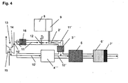
- the exhaust gas flow from the internal combustion engine branches before the turbine 14 of the exhaust gas turbocharger 13 into an exhaust main flow 10 ', which is guided via the turbine 14 and drives the compressor 15 via this and an exhaust gas partial flow 11'.
- the partial exhaust gas stream 11 ' is passed through an oxidation catalyst 16, which converts on the one hand in the normal direction indicated by the arrows flow direction of the exhaust gas nitrogen monoxide in nitrogen dioxide and on the other hand, for. B. oxidized possibly in the engine braking operation with the exhaust gas flow in the direction of the engine back flowing ammonia or back flowing unreacted reducing agent.
- a shut-off device 12 follows in the exhaust gas substream 11 ', which in construction and function in connection with FIG. 3 Applies to the described obturator, it is for this purpose in the relevant parts of the description of FIG. 3 directed. Downstream to the obturator is with a metering device as they already closed FIG. 2 is described, the reducing agent in the exhaust side stream 11 'is supplied, which splits off by the prevailing in the exhaust gas side stream relatively high exhaust gas temperature and the supply point downstream hydrolysis without the onset problematic reaction products such as cyanuric acid, ammonia.
- the exhaust main flow 10' is passed through an oxidation catalyst 4 "'which in turn oxidizes nitrogen monoxide contained in the exhaust gas to nitrogen dioxide the parallel exhaust gas flows again and flow through the downstream Pumbleabscheider 5, where, as already stated for the other embodiments, the particulate matter in the 5 deposited soot particles using the generated in the oxidation catalysts 4 '"and 16 nitrogen dioxide to carbon monoxide, carbon dioxide, nitrogen and nitrogen monoxide be implemented continuously.
- the particle separator is followed by an SCR catalytic converter 6 'which, by way of selective catalytic reduction, converts the nitrogen oxides present in the exhaust gas into nitrogen and water vapor.
- the SCR catalyst 6 ' is coated in its downstream region with an active material forming an NH 3 oxidation catalyst 7'.
- the turbine 14 deviates in deviation FIG. 4 it is advantageous to divert the partial exhaust gas flow from one of the two floods around a twin-flow turbine, wherein the one flood is fed by a first number of cylinders and the other flood of a second number of cylinders with exhaust gas.
- the cylinders of the tide, from which the partial exhaust gas stream branches off, can then be operated with other engine parameters (eg fuel injection times or amounts) than the cylinders of the other tide, so that optimizing the conditions in the exhaust gas partial stream with regard to the preparation of the reducing agent is advantageously possible
- the exhaust gas temperature in the starting phase or in the low load range, z. B. by a post-injection in the expansion or Ausschubtakt is raised.
- the cylinders of the cylinder bank branches from the exhaust tract of the exhaust gas partial stream, then with other engine parameters (eg Kraftstoffeinspritz réelle- or Amounts) are operated as the cylinder of the other cylinder bank, so that also here an optimization of the conditions in the exhaust gas partial stream with respect to the preparation of the reducing agent is possible by, for example, the exhaust gas temperature in the starting phase or in low load range, eg. B. by a post-injection in the expansion or Ausschubtakt, is raised.
- the active components of the catalysts can be applied to ceramic and / or metallic and / or silicate-containing and / or quartz-containing supports.
- Such catalysts can be prepared by means of many known preparation processes, it is expressly made to the relevant literature.
- Platinum and / or palladium and / or iridium and / or their oxides and / or IrTiOx and / or zeolites can be used as active materials for the oxidation catalysts mentioned in the preceding examples.
- active components for the SCR catalysts for the reduction of nitrogen oxides with the aid of ammonia vanadium and / or vanadium pentoxide and / or titanium dioxide and / or tungsten oxide and / or copper-containing zeolites and / or iron-containing zeolites and / or cobalt-containing zeolites are used.
- titanium dioxide and / or silicon dioxide and / or aluminum oxide and / or zeolites can be used as active components.
- the exhaust gas temperature and / or the content of nitrogen dioxide may be attached to the particulate depositors by adjusting engine parameters and / or by increasing the hydrocarbon concentration by adjusting engine parameters and / or by supplying engine parameters Hydrocarbons in the exhaust stream upstream of the catalysts for Oxidation of nitric oxide and / or hydrocarbons and / or carbon monoxide can be changed.
Landscapes
- Engineering & Computer Science (AREA)
- Chemical & Material Sciences (AREA)
- Combustion & Propulsion (AREA)
- Mechanical Engineering (AREA)
- General Engineering & Computer Science (AREA)
- Chemical Kinetics & Catalysis (AREA)
- Health & Medical Sciences (AREA)
- Toxicology (AREA)
- Physics & Mathematics (AREA)
- Electromagnetism (AREA)
- Exhaust Gas After Treatment (AREA)
Claims (18)
- Système de post-traitement des gaz d'échappement pour réduire les oxydes d'azote et les particules dans les moteurs à combustion interne fonctionnant avec un excédant d'air, selon lequel,
on réduit les oxydes d'azote à l'aide d'un catalyseur SCR (6, 6'), et
on réduit les particules à l'aide d'un séparateur de particules (5, 5') ou d'un filtre à particules,
procédé dans lequel,- un catalyseur d'oxydation (4, 4', 4", 4"', 16) est installé dans la veine des gaz d'échappement du moteur à combustion interne, ce catalyseur transforme au moins une partie du monoxyde d'azote contenu dans la veine des gaz d'échappement en dioxyde d'azote,- un réservoir (8) d'agent réducteur et son installation de dosage (9) sont prévus, l'installation de dosage (9) fournissant l'agent réducteur en parallèle au catalyseur d'oxydation (4, 4", 4''') dans une veine partielle de gaz d'échappement, dérivée en amont du catalyseur d'oxydation (4, 4", 4''') de la veine des gaz d'échappement et retournée dans la veine des gaz d'échappement en aval du catalyseur d'oxydation (4, 4", 4'''),- en amont du catalyseur d'oxydation (4'''), il est prévu au moins une turbine (14) d'au moins un turbocompresseur de gaz d'échappement (13), et la dérivation de la veine partielle de gaz d'échappement qui reçoit l'agent réducteur se trouve en amont de la turbine (14) du turbocompresseur de gaz d'échappement (13),- l'agent réducteur est une matière qui dégage de l'ammoniac sous l'effet des gaz d'échappement chauds en aval du point d'introduction,- en aval du catalyseur d'oxydation (4, 4', 4", 4"', 16) et en aval du point d'introduction de l'agent réducteur, le séparateur de particules (5, 5') ou filtre à particules dans la veine des gaz d'échappement transforme les particules de noir de fumée stockées dans le séparateur de particules (5, 5') ou le filtre à particules, à l'aide du dioxyde d'azote contenu dans la veine des gaz d'échappement pour donner du monoxyde de carbone, du dioxyde de carbone, de l'azote et du monoxyde d'azote,- en aval du séparateur de particules (5, 5') ou filtre à particules, se trouve le catalyseur SCR (6, 6') qui réduit les oxydes d'azote contenus dans la veine des gaz d'échappement à l'aide de l'ammoniac séparé au cours de la réduction catalytique sélective pour donner de l'azote et de la vapeur d'eau. - Système de post-traitement des gaz d'échappement selon la revendication 1,
caractérisé par
un catalyseur d'hydrolyse (3, 3', 3") pour améliorer le dégagement d'ammoniac, entre le point d'introduction de l'agent réducteur et le séparateur de particules (5, 5') ou filtre à particules. - Système de post-traitement des gaz d'échappement selon la revendication 2,
caractérisé en ce que
le catalyseur d'hydrolyse (3') et le séparateur de particules (5') ou le filtre à particules, sont réunis en un composant de façon que le séparateur de particules (5') ou le filtre à particules soit revêtu ou imprégné au moins en partie d'un composant actif formant le catalyseur d'hydrolyse (3'). - Système de post-traitement des gaz d'échappement selon la revendication 1 ou 2,
caractérisé en ce que
le catalyseur d'hydrolyse (3) et le catalyseur d'oxydation (4) constituent un composant commun de façon à être installés tous deux en parallèle dans un boîtier unique de façon que la veine partielle des gaz d'échappement ne traverse que le catalyseur d'hydrolyse (3) et que la veine des gaz d'échappement ne traverse que le catalyseur d'oxydation (4), et l'agent réducteur est ajouté à la veine partielle des gaz d'échappement qui ne traverse que le catalyseur d'hydrolyse (3). - Système de post-traitement des gaz d'échappement selon la revendication 4,
caractérisé en ce que
la turbine est alimentée par deux flux, un premier flux venant au moins d'un premier cylindre et l'autre flux d'au moins un second cylindre donnant des gaz d'échappement et la veine partielle des gaz d'échappement est dérivée de l'un des deux flux. - Système de post-traitement des gaz d'échappement selon la revendication 5,
caractérisé en ce que
les cylindres donnant le flux dont la veine partielle des gaz d'échappement est prélevée, fonctionnent selon d'autres paramètres de moteur que les cylindres de l'autre flux. - Système de post-traitement des gaz d'échappement selon la revendication 6,
caractérisé par
deux turbocompresseurs de gaz d'échappement dont la turbine de l'un est alimentée en gaz d'échappement à partir du premier banc de cylindres du moteur à combustion interne et dont la turbine de l'autre est alimentée en gaz d'échappement à partir du second banc de cylindres du moteur à combustion interne, et
la veine partielle des gaz d'échappement, est dérivée de la veine des gaz d'échappement en amont de la turbine de l'un des deux turbocompresseurs de gaz d'échappement. - Système de post-traitement des gaz d'échappement selon la revendication 7,
caractérisé en ce que
le banc de cylindres avec la conduite des gaz d'échappement dont est dérivée une veine partielle de gaz d'échappement, fonctionne selon d'autres paramètres du moteur que l'autre banc de cylindres. - Système de post-traitement des gaz d'échappement selon les revendications précédentes,
caractérisé par
un élément d'étranglement installé dans la veine partielle des gaz d'échappement, cet élément d'étranglement étant commandé et/ou régulé en fonction de la vitesse spatiale des gaz d'échappement et/ou des quantités de gaz d'échappement dans la conduite de dérivation. - Système de post-traitement des gaz d'échappement selon les revendications précédentes,
caractérisé par
un clapet antiretour installé dans la conduite partielle des gaz d'échappement, en amont de la conduite d'alimentation fournissant l'agent réducteur. - Système de post-traitement des gaz d'échappement selon les revendications précédentes,
caractérisé en ce qu'
un élément d'arrêt, commandé ou régulé (12) est prévu en amont du point d'introduction de l'agent réducteur dans la veine partielle des gaz d'échappement. - Système de post-traitement des gaz d'échappement selon les revendications précédentes,
caractérisé en ce qu'
un catalyseur d'oxydation NH3 (7, 7') est prévu en aval du catalyseur SCR (6, 6'). - Système de post-traitement des gaz d'échappement selon les revendications précédentes,
caractérisé en ce qu'
on utilise du platine et/ou du palladium et/ou de l'iridium et/ou leurs oxydes et/ou IrTiOx et/ou des zéolithes comme composant actif du catalyseur d'oxydation (4, 4', 4", 4"', 16), pour transformer le monoxyde d'azote en oxydes d'azote et/ou pour le catalyseur d'oxydation NH3 (7, 7') pour l'oxydation de l'ammoniac. - Système de post-traitement des gaz d'échappement selon les revendications précédentes,
caractérisé en ce que
pour réduire les oxydes d'azote à l'aide d'ammoniac, le catalyseur SCR (6, 6') comporte comme composants actifs, du vanadium et/ou du pentoxyde de vanadium et/ou du dioxyde de titane et/ou de l'oxyde de tungstène et/ou des zéolithes contenant du cuivre et/ou des zéolithes contenant du fer et/ou des zéolithes contenant du cobalt. - Système de post-traitement des gaz d'échappement selon les revendications 2 à 14,
caractérisé en ce que
pour libérer de l'ammoniac, le catalyseur d'hydrolyse (3, 3', 3") contient comme composants actifs, du dioxyde de titane et/ou du dioxyde de silicium et/ou de l'oxyde d'aluminium et/ou des zéolithes. - Système de post-traitement des gaz d'échappement selon les revendications précédentes,
caractérisé en ce que
la température des gaz d'échappement et/ou la teneur en dioxyde d'azote au niveau du séparateur de particules (5, 5') ou du filtre à particules se modifie(nt) par réglage des paramètres du moteur et/ou par relevage de la concentration en hydrocarbures à l'aide du réglage de paramètres du moteur et/ou par l'introduction d'hydrocarbures dans la veine des gaz d'échappement en amont du catalyseur d'oxydation (4, 4', 4", 4"', 16) pour oxyder le monoxyde d'azote. - Système de post-traitement des gaz d'échappement selon les revendications précédentes,
caractérisé par
plusieurs catalyseurs et/ou séparateurs de particules logés dans un boîtier commun. - Système de post-traitement des gaz d'échappement selon les revendications précédentes,
caractérisé en ce que
les filtres à particules et/ou les séparateurs de particules sont construits pour être interchangeables.
Applications Claiming Priority (1)
| Application Number | Priority Date | Filing Date | Title |
|---|---|---|---|
| DE102006038290A DE102006038290A1 (de) | 2006-08-16 | 2006-08-16 | Abgasnachbehandlungssystem |
Publications (2)
| Publication Number | Publication Date |
|---|---|
| EP1892394A1 EP1892394A1 (fr) | 2008-02-27 |
| EP1892394B1 true EP1892394B1 (fr) | 2009-05-13 |
Family
ID=38662834
Family Applications (1)
| Application Number | Title | Priority Date | Filing Date |
|---|---|---|---|
| EP07013161A Active EP1892394B1 (fr) | 2006-08-16 | 2007-07-05 | Système de traitement postérieur de gaz d'échappement |
Country Status (3)
| Country | Link |
|---|---|
| US (1) | US7937933B2 (fr) |
| EP (1) | EP1892394B1 (fr) |
| DE (2) | DE102006038290A1 (fr) |
Families Citing this family (27)
| Publication number | Priority date | Publication date | Assignee | Title |
|---|---|---|---|---|
| EP2126295B1 (fr) * | 2007-02-21 | 2015-08-05 | Volvo Lastvagnar AB | Système et procédé de post-traitement de gaz d'échappement |
| US20100199634A1 (en) * | 2007-05-02 | 2010-08-12 | David Mark Heaton | Exhaust treatment system implementing selective doc bypass |
| US7799289B2 (en) * | 2007-07-31 | 2010-09-21 | Caterpillar Inc | Exhaust treatment system with NO2 control |
| DE102007061005A1 (de) | 2007-12-18 | 2009-06-25 | Man Nutzfahrzeuge Ag | Verfahren zur Verbesserung der Hydrolyse eines Reduktionsmittels in einem Abgasnachbehandlungssystem |
| US20090173063A1 (en) * | 2008-01-07 | 2009-07-09 | Boorse R Samuel | Mitigation of Particulates and NOx in Engine Exhaust |
| JP5251266B2 (ja) * | 2008-06-03 | 2013-07-31 | いすゞ自動車株式会社 | 排気ガス浄化装置及び排気ガス浄化システム |
| KR101466697B1 (ko) * | 2008-07-10 | 2014-12-01 | 삼성전자주식회사 | 메모리 장치 및 메모리 데이터 프로그래밍 방법 |
| US20100170225A1 (en) * | 2009-01-08 | 2010-07-08 | Caterpillar Inc. | Exhaust treatment system having a reductant supply system |
| DE102009004418A1 (de) | 2009-01-13 | 2010-07-15 | Man Nutzfahrzeuge Ag | Verfahren zur Nachbehandlung eines Abgasstroms einer mehrzylindrigen Brennkraftmaschine eines Fahrzeuges sowie Abgasnachbehandlungsvorrichtung |
| DE102009004416A1 (de) | 2009-01-13 | 2010-07-15 | Man Nutzfahrzeuge Aktiengesellschaft | Verfahren zum Betrieb von Komponenten der Abgasnachbehandlung sowie Abgasnachbehandlungsvorrichung |
| DE102009004417A1 (de) | 2009-01-13 | 2010-07-15 | Man Nutzfahrzeuge Aktiengesellschaft | Verfahren zur Nachbehandlung eines Abgasstroms einer mehrzylindrigen Brennkraftmaschine eines Fahrzeuges sowie Abgasnachbehandlungsvorrichtung |
| BRPI1004924B1 (pt) | 2009-01-13 | 2020-07-21 | Man Truck & Bus Ag. | "método para funcionamento de componentes do tratamento posterior de gás de escape e dispositivo de tratamento posterior de gás de escape" |
| JP2010242515A (ja) * | 2009-04-01 | 2010-10-28 | Isuzu Motors Ltd | 排気ガス浄化システム及び排気ガス浄化方法 |
| DE102009024535A1 (de) | 2009-06-10 | 2010-12-16 | J. Eberspächer GmbH & Co. KG | Abgasnachbehandlungsvorrichtung |
| AT507633B1 (de) * | 2009-06-25 | 2012-06-15 | Avl List Gmbh | Abgasanlage mit einem abgasnachbehandlungssystem |
| DE102009032022A1 (de) * | 2009-07-07 | 2011-01-13 | Man Nutzfahrzeuge Aktiengesellschaft | Verfahren und Vorrichtung zur Regeneration eines im Abgastrakt einer Brennkraftmaschine angeordneten Partikelfilters |
| US8371108B2 (en) * | 2009-07-29 | 2013-02-12 | Ford Global Technologies, Llc | Twin turbo diesel aftertreatment system |
| DE102010025893A1 (de) | 2010-07-02 | 2012-01-05 | Audi Ag | Verfahren zur Nachbehandlung des Abgases einer Brennkraftmaschine, Abgasnachbehandlungsvorrichtung sowie Kraftwagen |
| KR101509689B1 (ko) * | 2011-07-01 | 2015-04-08 | 현대자동차 주식회사 | 배기 가스 정화 장치 및 이를 포함하는 배기 장치 |
| US8689544B2 (en) | 2011-07-15 | 2014-04-08 | GM Global Technology Operations LLC | Emission control system for a vehicle |
| CN103291419B (zh) * | 2012-02-29 | 2015-12-16 | 北京市劳动保护科学研究所 | 一种内燃机尾气净化装置 |
| DE102014201579B4 (de) * | 2013-02-13 | 2017-06-14 | Ford Global Technologies, Llc | Brennkraftmaschine mit selektivem Katalysator zur Reduzierung der Stickoxide und Verfahren zum Betreiben einer derartigen Brennkraftmaschine |
| DE102014201709B4 (de) * | 2013-02-15 | 2016-12-29 | Ford Global Technologies, Llc | Abgasturboaufgeladene Brennkraftmaschine mit Abgasnachbehandlung und Verfahren zum Betreiben einer derartigen Brennkraftmaschine |
| US10300435B2 (en) * | 2015-02-26 | 2019-05-28 | Ngk Spark Plug Co., Ltd. | Ammonia generation apparatus and ammonia generation control apparatus |
| FR3054857B1 (fr) * | 2016-08-04 | 2020-10-16 | Peugeot Citroen Automobiles Sa | Dispositif de post-traitement des gaz d’echappement d’un moteur thermique |
| DE102017123492A1 (de) * | 2017-10-10 | 2019-04-11 | Volkswagen Aktiengesellschaft | Abgasnachbehandlungssystem und Verfahren zur Abgasnachbehandlung eines Verbrennungsmotors |
| CN113864030B (zh) * | 2021-08-16 | 2022-06-14 | 安庆中船柴油机有限公司 | 一种柴油机机载尿素喷射系统 |
Family Cites Families (19)
| Publication number | Priority date | Publication date | Assignee | Title |
|---|---|---|---|---|
| DE3428232A1 (de) | 1984-07-31 | 1986-02-06 | Süd-Chemie AG, 8000 München | Katalysator zur entfernung von stickoxiden aus abgasen |
| US4902487A (en) | 1988-05-13 | 1990-02-20 | Johnson Matthey, Inc. | Treatment of diesel exhaust gases |
| DE4038054A1 (de) | 1990-11-29 | 1992-06-04 | Man Technologie Gmbh | Verfahren und vorrichtung zur selektiven katalytischen no(pfeil abwaerts)x(pfeil abwaerts)-reduktion in sauerstoffhaltigen abgasen |
| GB9802504D0 (en) | 1998-02-06 | 1998-04-01 | Johnson Matthey Plc | Improvements in emission control |
| US6615580B1 (en) * | 1999-06-23 | 2003-09-09 | Southwest Research Institute | Integrated system for controlling diesel engine emissions |
| DE19934932B4 (de) | 1999-07-26 | 2011-06-30 | MAN Truck & Bus AG, 80995 | Verfahren und Vorrichtung zur Abscheidung von Feinstpartikeln aus dem Abgas von Brennkraftmaschinen |
| DE10207986A1 (de) * | 2002-02-25 | 2003-09-04 | Daimler Chrysler Ag | Abgasreinigungsanlage für eine Brennkraftmaschine |
| DE10218255B4 (de) * | 2002-04-24 | 2005-07-07 | J. Eberspächer GmbH & Co. KG | Abgasanlage für einen Dieselmotor und zugehöriger Schalldämpfer |
| JP3791470B2 (ja) * | 2002-07-02 | 2006-06-28 | トヨタ自動車株式会社 | 内燃機関の排気浄化装置 |
| US6928806B2 (en) | 2002-11-21 | 2005-08-16 | Ford Global Technologies, Llc | Exhaust gas aftertreatment systems |
| US6832473B2 (en) * | 2002-11-21 | 2004-12-21 | Delphi Technologies, Inc. | Method and system for regenerating NOx adsorbers and/or particulate filters |
| US7229597B2 (en) * | 2003-08-05 | 2007-06-12 | Basfd Catalysts Llc | Catalyzed SCR filter and emission treatment system |
| JP4290037B2 (ja) * | 2004-03-02 | 2009-07-01 | 日産ディーゼル工業株式会社 | エンジンの排気浄化装置 |
| EP1799980A1 (fr) * | 2004-09-08 | 2007-06-27 | Donaldson Company, Inc. | Construction d'un composant d'un systeme d'echappement d'un moteur |
| US7402292B2 (en) * | 2005-09-19 | 2008-07-22 | Delphi Technologies, Inc. | Device and methods of ammonia generation for NOx abatement |
| US7610750B2 (en) * | 2006-07-25 | 2009-11-03 | Gm Global Technology Operations, Inc. | Method and apparatus for monitoring a urea injection system in an exhaust aftertreatment system |
| US7614214B2 (en) * | 2006-07-26 | 2009-11-10 | Eaton Corporation | Gasification of soot trapped in a particulate filter under reducing conditions |
| US7434387B2 (en) * | 2006-07-26 | 2008-10-14 | Eaton Corporation | Integrated DPF-reformer |
| DE102006038289A1 (de) * | 2006-08-16 | 2008-02-21 | Man Nutzfahrzeuge Aktiengesellschaft | Abgasnachbehandlungssystem |
-
2006
- 2006-08-16 DE DE102006038290A patent/DE102006038290A1/de not_active Withdrawn
-
2007
- 2007-07-05 EP EP07013161A patent/EP1892394B1/fr active Active
- 2007-07-05 DE DE502007000724T patent/DE502007000724D1/de active Active
- 2007-08-16 US US11/840,081 patent/US7937933B2/en active Active
Also Published As
| Publication number | Publication date |
|---|---|
| DE502007000724D1 (de) | 2009-06-25 |
| US7937933B2 (en) | 2011-05-10 |
| DE102006038290A1 (de) | 2008-02-21 |
| US20080041053A1 (en) | 2008-02-21 |
| EP1892394A1 (fr) | 2008-02-27 |
Similar Documents
| Publication | Publication Date | Title |
|---|---|---|
| EP1892395B1 (fr) | Système de traitement de gaz d'échappement | |
| EP1900916B1 (fr) | Système de traitement postérieur de gaz d'échappement | |
| EP2101049B1 (fr) | Système de post-traitement de gaz d'échappement compact | |
| EP1892394A1 (fr) | Système de traitement postérieur de gaz d'échappement | |
| EP1985819B1 (fr) | Système de traitement de gaz d'échappement | |
| EP1892396B1 (fr) | Système de traitement de gaz d'échappement | |
| EP2075050B1 (fr) | Procédé et dispositif d'amélioration de l'hydrolyse d'un moyen de réduction dans un système de retraitement des gaz d'échappement | |
| DE102008017280B4 (de) | Anordnung zur Beeinflussung des Umsatzverhaltens von Abgaskatalysatoren | |
| EP2037091B1 (fr) | Système de traitement postérieur de gaz d'échappement autonettoyant | |
| EP2154344B1 (fr) | Procédé et dispositif de régénération d'un filtre à particules agencé dans une ligne d'échappement d'un moteur à combustion interne | |
| EP2379851B1 (fr) | Dispositif et procédé de régénération d'un filtre à particules disposé dans la conduite de gaz d'échappement d'un moteur à combustion interne | |
| EP2154345B1 (fr) | Procédé et dispositif de régénération d'un filtre à particules agencé dans le système d'échappement d'un moteur à combustion interne | |
| EP2644857B1 (fr) | Procédé destiné à l'utilisation en liaison avec un dispositif de post-traitement de gaz d'échappement | |
| EP1771644A1 (fr) | Systeme d'echappement, notamment pour un moteur a combustion interne d'un vehicule a moteur | |
| EP2280155A2 (fr) | Procédé et dispositif de nettoyage d'un flux de gaz d'échappement d'un moteur à combustion interne | |
| WO2020069548A1 (fr) | Procédé et moteur à allumage commandé équipé d'un système scr amélioré | |
| EP2107222B1 (fr) | Procédé d'accentuation de la part de dioxyde d'azote dans les gaz d'échappement | |
| EP2166207B1 (fr) | Dispositif et procédé de purification d'un flux de gaz d'échappement d'un moteur à combustion interne, notamment d'un moteur à combustion interne à mélange pauvre | |
| EP2659950B1 (fr) | Système de traitement postérieur de gaz d'échappement | |
| AT521743B1 (de) | Verfahren und Ottomotoranordnung mit einem verbesserten SCR-System | |
| DE102020100534A1 (de) | Abgasnachbehandlungssystem sowie Verfahren zur Abgasnachbehandlung eines Verbrennungsmotors |
Legal Events
| Date | Code | Title | Description |
|---|---|---|---|
| PUAI | Public reference made under article 153(3) epc to a published international application that has entered the european phase |
Free format text: ORIGINAL CODE: 0009012 |
|
| AK | Designated contracting states |
Kind code of ref document: A1 Designated state(s): AT BE BG CH CY CZ DE DK EE ES FI FR GB GR HU IE IS IT LI LT LU LV MC MT NL PL PT RO SE SI SK TR |
|
| AX | Request for extension of the european patent |
Extension state: AL BA HR MK YU |
|
| 17P | Request for examination filed |
Effective date: 20080313 |
|
| 17Q | First examination report despatched |
Effective date: 20080409 |
|
| AKX | Designation fees paid |
Designated state(s): DE FR IT NL SE |
|
| GRAP | Despatch of communication of intention to grant a patent |
Free format text: ORIGINAL CODE: EPIDOSNIGR1 |
|
| RTI1 | Title (correction) |
Free format text: EXHAUST GAS AFTERTREATMENT SYSTEM |
|
| GRAS | Grant fee paid |
Free format text: ORIGINAL CODE: EPIDOSNIGR3 |
|
| GRAA | (expected) grant |
Free format text: ORIGINAL CODE: 0009210 |
|
| AK | Designated contracting states |
Kind code of ref document: B1 Designated state(s): DE FR IT NL SE |
|
| REF | Corresponds to: |
Ref document number: 502007000724 Country of ref document: DE Date of ref document: 20090625 Kind code of ref document: P |
|
| REG | Reference to a national code |
Ref country code: SE Ref legal event code: TRGR |
|
| PLBE | No opposition filed within time limit |
Free format text: ORIGINAL CODE: 0009261 |
|
| 26N | No opposition filed |
Effective date: 20100216 |
|
| REG | Reference to a national code |
Ref country code: NL Ref legal event code: TD Effective date: 20110304 |
|
| REG | Reference to a national code |
Ref country code: FR Ref legal event code: CD |
|
| REG | Reference to a national code |
Ref country code: DE Ref legal event code: R081 Ref document number: 502007000724 Country of ref document: DE Owner name: MAN TRUCK & BUS AG, DE Free format text: FORMER OWNER: MAN NUTZFAHRZEUGE AG, 80995 MUENCHEN, DE Effective date: 20110406 |
|
| PLAA | Information modified related to event that no opposition was filed |
Free format text: ORIGINAL CODE: 0009299DELT |
|
| PLBE | No opposition filed within time limit |
Free format text: ORIGINAL CODE: 0009261 |
|
| STAA | Information on the status of an ep patent application or granted ep patent |
Free format text: STATUS: NO OPPOSITION FILED WITHIN TIME LIMIT |
|
| R26N | No opposition filed (corrected) |
Effective date: 20100216 |
|
| RIN2 | Information on inventor provided after grant (corrected) |
Inventor name: DOERING, ANDREAS Inventor name: SPANIOL, PETER |
|
| REG | Reference to a national code |
Ref country code: FR Ref legal event code: PLFP Year of fee payment: 10 |
|
| REG | Reference to a national code |
Ref country code: FR Ref legal event code: PLFP Year of fee payment: 11 |
|
| REG | Reference to a national code |
Ref country code: FR Ref legal event code: PLFP Year of fee payment: 12 |
|
| REG | Reference to a national code |
Ref country code: DE Ref legal event code: R081 Ref document number: 502007000724 Country of ref document: DE Owner name: MAN TRUCK & BUS SE, DE Free format text: FORMER OWNER: MAN TRUCK & BUS AG, 80995 MUENCHEN, DE |
|
| PGFP | Annual fee paid to national office [announced via postgrant information from national office to epo] |
Ref country code: NL Payment date: 20250724 Year of fee payment: 19 |
|
| PGFP | Annual fee paid to national office [announced via postgrant information from national office to epo] |
Ref country code: DE Payment date: 20250728 Year of fee payment: 19 |
|
| PGFP | Annual fee paid to national office [announced via postgrant information from national office to epo] |
Ref country code: IT Payment date: 20250721 Year of fee payment: 19 |
|
| PGFP | Annual fee paid to national office [announced via postgrant information from national office to epo] |
Ref country code: FR Payment date: 20250725 Year of fee payment: 19 |
|
| PGFP | Annual fee paid to national office [announced via postgrant information from national office to epo] |
Ref country code: SE Payment date: 20250725 Year of fee payment: 19 |