EP1892440A1 - Piston - Google Patents
Piston Download PDFInfo
- Publication number
- EP1892440A1 EP1892440A1 EP07014563A EP07014563A EP1892440A1 EP 1892440 A1 EP1892440 A1 EP 1892440A1 EP 07014563 A EP07014563 A EP 07014563A EP 07014563 A EP07014563 A EP 07014563A EP 1892440 A1 EP1892440 A1 EP 1892440A1
- Authority
- EP
- European Patent Office
- Prior art keywords
- piston
- seal
- cylinder
- piston according
- annular groove
- Prior art date
- Legal status (The legal status is an assumption and is not a legal conclusion. Google has not performed a legal analysis and makes no representation as to the accuracy of the status listed.)
- Withdrawn
Links
Images
Classifications
-
- F—MECHANICAL ENGINEERING; LIGHTING; HEATING; WEAPONS; BLASTING
- F16—ENGINEERING ELEMENTS AND UNITS; GENERAL MEASURES FOR PRODUCING AND MAINTAINING EFFECTIVE FUNCTIONING OF MACHINES OR INSTALLATIONS; THERMAL INSULATION IN GENERAL
- F16J—PISTONS; CYLINDERS; SEALINGS
- F16J15/00—Sealings
- F16J15/56—Other sealings for reciprocating rods
-
- F—MECHANICAL ENGINEERING; LIGHTING; HEATING; WEAPONS; BLASTING
- F15—FLUID-PRESSURE ACTUATORS; HYDRAULICS OR PNEUMATICS IN GENERAL
- F15B—SYSTEMS ACTING BY MEANS OF FLUIDS IN GENERAL; FLUID-PRESSURE ACTUATORS, e.g. SERVOMOTORS; DETAILS OF FLUID-PRESSURE SYSTEMS, NOT OTHERWISE PROVIDED FOR
- F15B15/00—Fluid-actuated devices for displacing a member from one position to another; Gearing associated therewith
- F15B15/08—Characterised by the construction of the motor unit
- F15B15/14—Characterised by the construction of the motor unit of the straight-cylinder type
- F15B15/1423—Component parts; Constructional details
- F15B15/1447—Pistons; Piston to piston rod assemblies
- F15B15/1452—Piston sealings
-
- F—MECHANICAL ENGINEERING; LIGHTING; HEATING; WEAPONS; BLASTING
- F16—ENGINEERING ELEMENTS AND UNITS; GENERAL MEASURES FOR PRODUCING AND MAINTAINING EFFECTIVE FUNCTIONING OF MACHINES OR INSTALLATIONS; THERMAL INSULATION IN GENERAL
- F16D—COUPLINGS FOR TRANSMITTING ROTATION; CLUTCHES; BRAKES
- F16D25/00—Fluid-actuated clutches
- F16D25/08—Fluid-actuated clutches with fluid-actuated member not rotating with a clutching member
-
- F—MECHANICAL ENGINEERING; LIGHTING; HEATING; WEAPONS; BLASTING
- F16—ENGINEERING ELEMENTS AND UNITS; GENERAL MEASURES FOR PRODUCING AND MAINTAINING EFFECTIVE FUNCTIONING OF MACHINES OR INSTALLATIONS; THERMAL INSULATION IN GENERAL
- F16D—COUPLINGS FOR TRANSMITTING ROTATION; CLUTCHES; BRAKES
- F16D25/00—Fluid-actuated clutches
- F16D25/08—Fluid-actuated clutches with fluid-actuated member not rotating with a clutching member
- F16D25/088—Fluid-actuated clutches with fluid-actuated member not rotating with a clutching member the line of action of the fluid-actuated members being distinctly separate from the axis of rotation
-
- F—MECHANICAL ENGINEERING; LIGHTING; HEATING; WEAPONS; BLASTING
- F16—ENGINEERING ELEMENTS AND UNITS; GENERAL MEASURES FOR PRODUCING AND MAINTAINING EFFECTIVE FUNCTIONING OF MACHINES OR INSTALLATIONS; THERMAL INSULATION IN GENERAL
- F16D—COUPLINGS FOR TRANSMITTING ROTATION; CLUTCHES; BRAKES
- F16D25/00—Fluid-actuated clutches
- F16D25/12—Details not specific to one of the before-mentioned types
-
- F—MECHANICAL ENGINEERING; LIGHTING; HEATING; WEAPONS; BLASTING
- F16—ENGINEERING ELEMENTS AND UNITS; GENERAL MEASURES FOR PRODUCING AND MAINTAINING EFFECTIVE FUNCTIONING OF MACHINES OR INSTALLATIONS; THERMAL INSULATION IN GENERAL
- F16D—COUPLINGS FOR TRANSMITTING ROTATION; CLUTCHES; BRAKES
- F16D48/00—External control of clutches
- F16D48/02—Control by fluid pressure
-
- F—MECHANICAL ENGINEERING; LIGHTING; HEATING; WEAPONS; BLASTING
- F16—ENGINEERING ELEMENTS AND UNITS; GENERAL MEASURES FOR PRODUCING AND MAINTAINING EFFECTIVE FUNCTIONING OF MACHINES OR INSTALLATIONS; THERMAL INSULATION IN GENERAL
- F16J—PISTONS; CYLINDERS; SEALINGS
- F16J15/00—Sealings
- F16J15/16—Sealings between relatively-moving surfaces
- F16J15/32—Sealings between relatively-moving surfaces with elastic sealings, e.g. O-rings
- F16J15/3204—Sealings between relatively-moving surfaces with elastic sealings, e.g. O-rings with at least one lip
- F16J15/3232—Sealings between relatively-moving surfaces with elastic sealings, e.g. O-rings with at least one lip having two or more lips
- F16J15/3236—Sealings between relatively-moving surfaces with elastic sealings, e.g. O-rings with at least one lip having two or more lips with at least one lip for each surface, e.g. U-cup packings
-
- F—MECHANICAL ENGINEERING; LIGHTING; HEATING; WEAPONS; BLASTING
- F16—ENGINEERING ELEMENTS AND UNITS; GENERAL MEASURES FOR PRODUCING AND MAINTAINING EFFECTIVE FUNCTIONING OF MACHINES OR INSTALLATIONS; THERMAL INSULATION IN GENERAL
- F16D—COUPLINGS FOR TRANSMITTING ROTATION; CLUTCHES; BRAKES
- F16D25/00—Fluid-actuated clutches
- F16D25/08—Fluid-actuated clutches with fluid-actuated member not rotating with a clutching member
- F16D2025/081—Hydraulic devices that initiate movement of pistons in secondary cylinders for actuating clutches, i.e. primary cylinders
-
- F—MECHANICAL ENGINEERING; LIGHTING; HEATING; WEAPONS; BLASTING
- F16—ENGINEERING ELEMENTS AND UNITS; GENERAL MEASURES FOR PRODUCING AND MAINTAINING EFFECTIVE FUNCTIONING OF MACHINES OR INSTALLATIONS; THERMAL INSULATION IN GENERAL
- F16D—COUPLINGS FOR TRANSMITTING ROTATION; CLUTCHES; BRAKES
- F16D48/00—External control of clutches
- F16D48/02—Control by fluid pressure
- F16D2048/0212—Details of pistons for primary or secondary cylinders especially adapted for fluid control
-
- F—MECHANICAL ENGINEERING; LIGHTING; HEATING; WEAPONS; BLASTING
- F16—ENGINEERING ELEMENTS AND UNITS; GENERAL MEASURES FOR PRODUCING AND MAINTAINING EFFECTIVE FUNCTIONING OF MACHINES OR INSTALLATIONS; THERMAL INSULATION IN GENERAL
- F16D—COUPLINGS FOR TRANSMITTING ROTATION; CLUTCHES; BRAKES
- F16D48/00—External control of clutches
- F16D48/02—Control by fluid pressure
- F16D2048/0215—Control by fluid pressure for damping of pulsations within the fluid system
Definitions
- the present invention relates to a piston for a cylinder, in particular piston for a master cylinder or slave cylinder of a hydraulic system, in particular a hydraulic system for actuating a vehicle clutch or service brake of a motor vehicle, wherein the piston and the cylinder include a pressure chamber by means of a seal against a Overflow or sealed against the environment.
- the invention further relates to a method for producing such a piston.
- the seal in the prior art is either in a groove on the piston or it is axially fixed by an additional component.
- the tool parting plane is also located in the groove base, among other things. Since in the groove base, the seal of the cylinder are sealed arise in known arrangements of seals on pistons due to excessive tool offset and a resulting axially extending burr after demolding of the injection molding from the mold or template problems in the tightness.
- An object of the present invention is to improve the reliability of the sealing effect between piston and seal.
- a piston for a cylinder in particular piston for a master cylinder or slave cylinder of a hydraulic system, in particular a hydraulic system for actuating a vehicle clutch or service brake of a motor vehicle
- the piston and the cylinder include a pressure chamber, which by means of a seal a follow-up space or sealed to the environment, wherein the piston has a seal receptacle with a substantially conical seal seat for receiving the seal.
- the seal receptacle comprises a circumferential annular groove, into which engages a circumferential bulge of the seal. By embracing the annular groove through the bulge, a positive connection between the piston and seal is produced. The seal can be pushed over the conical seal seat for mounting.
- the seal thus has an additional bulge at the inner diameter of the seal back. This engages in the circumferential groove of the piston. As a result, the seal is fixed to the piston. The seal between the piston and seal takes place at the inner lip of the seal. At this point, the plastic piston can be demolded in the axial direction whereby the seal seat has no tool offset or burr-free.
- the circumferential annular groove preferably has a substantially trapezoidal cross-section. It is preferably provided that the circumferential bulge has a corresponding to the circumferential annular groove cross-section. It is preferably provided that the circumferential annular groove is arranged on the side facing away from the pressure chamber of the seal holder.
- the piston is preferably made of plastic e.g. manufactured as an injection molded part. It is preferably provided that the conical seal seat was produced by means of an axially demoulding die.
- the seal seat is preferably formed without burrs, preferably by the conical seal seat is made by means of an axially demoulding die.
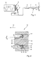
- Fig. 1 shows a schematic representation of a possible embodiment of a hydraulic system 1 with a pressure relief valve (Kribbelfilter) 2, a master cylinder 4, a slave cylinder 5.
- the slave cylinder 5 actuates a clutch release 3.
- the clutch release 3 actuates the clutch 8 hydraulically by acting on the master cylinder 4 by means of an actuator 9, a foot pedal, an actuator, For example, an electric actuator, or the like may be.
- 10 pressure in the master cylinder 4 is constructed by means of a mechanical transmission, which builds up a pressure in the slave cylinder 5 via the pressure line 7 and the pressure limiting valve 2 arranged therein.
- the slave cylinder 5 is actuated via a release mechanism 6, a non-illustrated releaser, such as a release bearing, for example, actuates a clutch disc via a plate spring.
- the slave cylinder 5 may alternatively be arranged concentrically around the transmission input shaft 11 and axially supported on a not shown - gear housing and apply the necessary disengaging force on the release bearing on the clutch 8, or on the release elements such as a plate spring.
- To apply the disengagement of the slave cylinder 5 is fixed to the housing respectively on the gear housing, which is not shown here, or attached to another housing-fixed component.
- the transmission input shaft 11 transmits, with the clutch 8, the torque of the internal combustion engine 12 to a not-shown gear and then to the drive wheels of a motor vehicle.
- the pressure limiting valve 2 is arranged in the pressure line 7 for damping vibrations that are introduced into the hydraulic system by the crankshaft and the clutch via the slave cylinder.
- the piston / cylinder arrangement 14 can be, for example, the master cylinder 4 or the slave cylinder 5 according to FIG.
- the piston / cylinder assembly 14 includes a piston 15 which is movably disposed in a cylinder 16.
- the piston 15 and the cylinder 16 include a pressure chamber 17 a.
- a hydraulic connection for connection to the pressure line 7 is provided with a donor and a slave cylinder, in a master cylinder, a sniffer device is additionally present, for example, with the piston 15th can interact in the manner of a valve.
- the piston 15 is pressed by a preload spring 18 in one direction, the arrangement and pressure direction of the preload spring 18 depends on the intended use of the piston / cylinder assembly as master cylinder 4 or slave cylinder 5 from.
- a seal 19 seals the pressure chamber 17 against a follow-up space or the environment over which the pressure chamber 17 is connected by means of a gap 20 between the piston 15 and the cylinder 16 from. Along the gap 20 more seals can follow, so z. B. the seal 19 may be a primary seal at a master cylinder, to which a secondary seal to the seal of the enclosed between the two Follow-up space can connect to the environment.
- the piston 15 comprises a piston body 21, which has approximately an outer diameter slightly smaller than the inner diameter of the cylinder 16, so that between them is a clearance fit.
- a seal receptacle 22 connects to the piston body 21.
- the seal seat 22 has a smaller diameter than the piston body 21.
- the seal seat 22 includes a substantially conical seal seat 23.
- the conical surface of the seal seat 23 is thus inclined by an angle ⁇ with respect to a rotation axis 24 of the piston / cylinder assembly 14.
- the transition of the piston body 21 to the seal seat 22 is formed by a disc-shaped contact surface 25, which, viewed in the direction of the pressure chamber 17, merges into a substantially trapezoidal circumferential annular groove 26.
- the encircling annular groove 26 comprises a first bevel 27, which is inclined in the direction of the rotation axis 24 as viewed from the contact surface 25, and a second bevel 28, which is arranged approximately perpendicular to the rotation axis 24 and thus approximately parallel to the contact surface 25.
- the circumferential annular groove 26 thus forms an undercut, which is arranged between the seal seat 23 and the contact surface 25.
- the piston 15 is made at least in the region of receiving the seal 19 made of a thermoplastic material as an injection molded part.
- the seal 19 comprises a piston-side sealing lip 29, which merges in the direction of the contact surface 25 in a circumferential bulge 30.
- the circumferential bulge 30 is arranged on a sealing back 31, which merges into a cylinder-side sealing lip 32.
- the piston-side sealing lip 29 and the circumferential bulge 30 correspond to the circumferential annular groove 26 and the seal seat 23 and together form a positive connection with this.
- the seal seat 23 by the bevel ⁇ allows a manufacturing process in which a die of a pressure or injection molding in the direction of arrow 33 can be deducted.
- the remaining parts of the piston 14 may be formed, for example, with a separate in the drawing plane of FIG. 2 die.
- the circumferential annular groove 26 can also be formed. With this measure, no Entformungsgrat on the seal seat 23 is present. As a result, the sealing effect between the seal seat 23 and the piston-side sealing lip 29 is not impaired.
Landscapes
- Engineering & Computer Science (AREA)
- General Engineering & Computer Science (AREA)
- Mechanical Engineering (AREA)
- Physics & Mathematics (AREA)
- Fluid Mechanics (AREA)
- Hydraulic Clutches, Magnetic Clutches, Fluid Clutches, And Fluid Joints (AREA)
Applications Claiming Priority (1)
| Application Number | Priority Date | Filing Date | Title |
|---|---|---|---|
| DE102006039543 | 2006-08-23 |
Publications (1)
| Publication Number | Publication Date |
|---|---|
| EP1892440A1 true EP1892440A1 (fr) | 2008-02-27 |
Family
ID=38752512
Family Applications (1)
| Application Number | Title | Priority Date | Filing Date |
|---|---|---|---|
| EP07014563A Withdrawn EP1892440A1 (fr) | 2006-08-23 | 2007-07-25 | Piston |
Country Status (1)
| Country | Link |
|---|---|
| EP (1) | EP1892440A1 (fr) |
Cited By (2)
| Publication number | Priority date | Publication date | Assignee | Title |
|---|---|---|---|---|
| WO2022057962A1 (fr) * | 2020-04-24 | 2022-03-24 | Schaeffler Technologies AG & Co. KG | Système de débrayage |
| CN117377601A (zh) * | 2021-05-27 | 2024-01-09 | 罗伯特·博世有限公司 | 存储器活塞装置 |
Citations (4)
| Publication number | Priority date | Publication date | Assignee | Title |
|---|---|---|---|---|
| US4281590A (en) * | 1979-01-02 | 1981-08-04 | Weaver Joe T | Piston construction for reciprocating pumps |
| US5865442A (en) * | 1996-06-12 | 1999-02-02 | Kurashiki Kako Co., Ltd. | Lip-like seal |
| DE19915022A1 (de) * | 1999-04-01 | 2000-10-26 | Bruss Dichtungstechnik | Elastomerdichtung zwischen einem Kolben und einem Zylinder und/oder einem Schaft eines automatischen Kraftfahrzeuggetriebes |
| EP1164316A2 (fr) * | 2000-06-09 | 2001-12-19 | FTE automotive GmbH | Actionneur hydraulique pour une tringle de commande d'une boíte de vitesse |
-
2007
- 2007-07-25 EP EP07014563A patent/EP1892440A1/fr not_active Withdrawn
Patent Citations (4)
| Publication number | Priority date | Publication date | Assignee | Title |
|---|---|---|---|---|
| US4281590A (en) * | 1979-01-02 | 1981-08-04 | Weaver Joe T | Piston construction for reciprocating pumps |
| US5865442A (en) * | 1996-06-12 | 1999-02-02 | Kurashiki Kako Co., Ltd. | Lip-like seal |
| DE19915022A1 (de) * | 1999-04-01 | 2000-10-26 | Bruss Dichtungstechnik | Elastomerdichtung zwischen einem Kolben und einem Zylinder und/oder einem Schaft eines automatischen Kraftfahrzeuggetriebes |
| EP1164316A2 (fr) * | 2000-06-09 | 2001-12-19 | FTE automotive GmbH | Actionneur hydraulique pour une tringle de commande d'une boíte de vitesse |
Cited By (2)
| Publication number | Priority date | Publication date | Assignee | Title |
|---|---|---|---|---|
| WO2022057962A1 (fr) * | 2020-04-24 | 2022-03-24 | Schaeffler Technologies AG & Co. KG | Système de débrayage |
| CN117377601A (zh) * | 2021-05-27 | 2024-01-09 | 罗伯特·博世有限公司 | 存储器活塞装置 |
Similar Documents
| Publication | Publication Date | Title |
|---|---|---|
| DE10262406B3 (de) | Kupplungsausrückvorrichtung und Verfahren zur Montage eines Kolbens einer Kupplungsausrückvorrichtung | |
| EP0615085B1 (fr) | Méthode de fabrication d'un joint d'étanchéité à lèvres | |
| DE112007000291B4 (de) | Vorrichtung zur Betätigung einer Kupplung | |
| DE10351907B4 (de) | Hydraulisches System | |
| DE10039242A1 (de) | Ausrücksystem | |
| DE10106958A1 (de) | Hydraulisches System | |
| DE10327437A1 (de) | Hydraulisches System | |
| WO2003100260A2 (fr) | Systeme hydraulique, en particulier pour vehicules a moteur | |
| EP2831453A1 (fr) | Frein à disque, en particulier pour un véhicule utilitaire | |
| DE102020113100A1 (de) | Zentralausrückeranordnung | |
| DE102014208085A1 (de) | 2K-Hybriddichtung und Brems-/ Kupplungsgeberzylinder mit 2K-Primärdichtung | |
| DE102008052446B4 (de) | Kupplungsnehmerzylinder | |
| EP3175153A1 (fr) | Dispositif d'actionnement hydraulique pour actionner des actionneurs dans une boîte de vitesses de véhicule automobile | |
| WO2009092463A1 (fr) | Système de vérin pour un actionneur d’embrayage commandé par un fluide sous pression | |
| DE102007034616A1 (de) | Kolben | |
| DE102015211831A1 (de) | Ausrücksystem für ein Kupplungsbetätigungssystem, insbesondere mit einer pneumatischen Übertragungsstrecke | |
| EP2009308B1 (fr) | Système de déclenchement à couplage | |
| DE102011087103A1 (de) | Geberzylinder | |
| DE102022133562B4 (de) | Kupplungsanordnung mit Entlüftungsfunktion | |
| DE102015200471A1 (de) | Verstelleinheit | |
| DE102015217582A1 (de) | Hydraulischer Aktor zur Betätigung einer Reibkupplung | |
| DE102018115882A1 (de) | Zentralaktuator für eine hydraulische oder pneumatische Kupplungsbetätigung | |
| DE102013209995A1 (de) | Kupplungsanordnung, insbesondere für eine Reibungskupplung in einem Kupplungsausrücksystem eines Kraftfahrzeuges | |
| DE10358836A1 (de) | Hydraulisches System | |
| DE102022133448B4 (de) | Nehmerzylinder mit vormontierter Dichtscheibe |
Legal Events
| Date | Code | Title | Description |
|---|---|---|---|
| PUAI | Public reference made under article 153(3) epc to a published international application that has entered the european phase |
Free format text: ORIGINAL CODE: 0009012 |
|
| AK | Designated contracting states |
Kind code of ref document: A1 Designated state(s): AT BE BG CH CY CZ DE DK EE ES FI FR GB GR HU IE IS IT LI LT LU LV MC MT NL PL PT RO SE SI SK TR |
|
| AX | Request for extension of the european patent |
Extension state: AL BA HR MK YU |
|
| 17P | Request for examination filed |
Effective date: 20080827 |
|
| 17Q | First examination report despatched |
Effective date: 20081001 |
|
| AKX | Designation fees paid |
Designated state(s): AT BE BG CH CY CZ DE DK EE ES FI FR GB GR HU IE IS IT LI LT LU LV MC MT NL PL PT RO SE SI SK TR |
|
| STAA | Information on the status of an ep patent application or granted ep patent |
Free format text: STATUS: THE APPLICATION IS DEEMED TO BE WITHDRAWN |
|
| 18D | Application deemed to be withdrawn |
Effective date: 20090212 |
|
| P01 | Opt-out of the competence of the unified patent court (upc) registered |
Effective date: 20230523 |