EP1892441B1 - Joint de tête de cylindre - Google Patents
Joint de tête de cylindre Download PDFInfo
- Publication number
- EP1892441B1 EP1892441B1 EP07015424.0A EP07015424A EP1892441B1 EP 1892441 B1 EP1892441 B1 EP 1892441B1 EP 07015424 A EP07015424 A EP 07015424A EP 1892441 B1 EP1892441 B1 EP 1892441B1
- Authority
- EP
- European Patent Office
- Prior art keywords
- sheet metal
- cylinder head
- combustion chamber
- head gasket
- metal layer
- Prior art date
- Legal status (The legal status is an assumption and is not a legal conclusion. Google has not performed a legal analysis and makes no representation as to the accuracy of the status listed.)
- Active
Links
Images
Classifications
-
- F—MECHANICAL ENGINEERING; LIGHTING; HEATING; WEAPONS; BLASTING
- F16—ENGINEERING ELEMENTS AND UNITS; GENERAL MEASURES FOR PRODUCING AND MAINTAINING EFFECTIVE FUNCTIONING OF MACHINES OR INSTALLATIONS; THERMAL INSULATION IN GENERAL
- F16J—PISTONS; CYLINDERS; SEALINGS
- F16J15/00—Sealings
- F16J15/02—Sealings between relatively-stationary surfaces
- F16J15/06—Sealings between relatively-stationary surfaces with solid packing compressed between sealing surfaces
- F16J15/08—Sealings between relatively-stationary surfaces with solid packing compressed between sealing surfaces with exclusively metal packing
- F16J15/0818—Flat gaskets
-
- F—MECHANICAL ENGINEERING; LIGHTING; HEATING; WEAPONS; BLASTING
- F02—COMBUSTION ENGINES; HOT-GAS OR COMBUSTION-PRODUCT ENGINE PLANTS
- F02F—CYLINDERS, PISTONS OR CASINGS, FOR COMBUSTION ENGINES; ARRANGEMENTS OF SEALINGS IN COMBUSTION ENGINES
- F02F11/00—Arrangements of sealings in combustion engines
- F02F11/002—Arrangements of sealings in combustion engines involving cylinder heads
-
- F—MECHANICAL ENGINEERING; LIGHTING; HEATING; WEAPONS; BLASTING
- F16—ENGINEERING ELEMENTS AND UNITS; GENERAL MEASURES FOR PRODUCING AND MAINTAINING EFFECTIVE FUNCTIONING OF MACHINES OR INSTALLATIONS; THERMAL INSULATION IN GENERAL
- F16J—PISTONS; CYLINDERS; SEALINGS
- F16J15/00—Sealings
- F16J15/02—Sealings between relatively-stationary surfaces
- F16J15/06—Sealings between relatively-stationary surfaces with solid packing compressed between sealing surfaces
- F16J15/08—Sealings between relatively-stationary surfaces with solid packing compressed between sealing surfaces with exclusively metal packing
- F16J15/0818—Flat gaskets
- F16J2015/0862—Flat gaskets with a bore ring
Definitions
- the invention relates to a cylinder head gasket for a multi-cylinder engine, in particular for a commercial vehicle diesel engine, which has a single-layer sealing plate with a single sheet metal layer, combustion chamber openings and for each combustion chamber opening at least one annular combustion chamber sealing element which surrounds the associated combustion chamber opening and has the shape of a arranged on the sheet metal layer and materially connected thereto by welding metal sheet ring.
- the present invention relates to such cylinder head gaskets in which is sealed around a combustion chamber opening around only with a metal ring, so that it forms the single combustion chamber sealing element.
- cylinder head gaskets of the type mentioned are designed as flat rings metal rings on that side of the sheet metal layer (usually and hereinafter referred to as support plate), which is facing the cylinder head with built-in seal.
- the sheet metal rings are connected to the carrier sheet, which is flat under the sheet metal rings, by welding, namely by spot welding or by means of continuous welds.
- the material of the welds or welds used to fasten the sheet metal rings frequently overhangs the metal rings, albeit only slightly, and secondly, the material melted during welding and then solidifies "Welding cores" which, when the cylinder head gasket is mounted and pressed, are subjected to high compressive forces and thereby pressed towards the inside of the carrier sheet.
- a cylinder head gasket for a multi-cylinder engine which has a single-layer gasket plate with a single, over the entire gasket plate extending sheet metal layer, combustion chamber openings and for each combustion chamber opening on each side of the sheet metal layer, an annular combustion chamber sealing element, the associated combustion chamber Opening surrounds and has the shape of a arranged on the sheet metal layer and directly connected thereto by welding metal sheet ring, wherein the metal sheet rings are the only Form combustion chamber sealing elements.
- this known cylinder head gasket all metal sheet rings and the sheet metal layer are flat overall.
- the sealing plate has a single, over the entire gasket plate extending sheet metal layer and for each combustion chamber opening a surrounding this metal sheet ring, which is connected to the sheet metal layer, however, via a likewise annular plastic layer.
- Fig. 1 is sealed around each combustion chamber opening by means of a provided in the sheet metal layer bead, for which the sheet metal ring forms a deformation limiter, that is, a so-called stopper.
- the DE-A-100 21 975 leaves open whether the metal sheet rings with built-in cylinder head gasket on the cylinder head or the engine block facing side of the sheet metal layer.
- a cylinder head gasket for a multi-cylinder engine having a gasket plate with a single metal sheet layer extending over the entire gasket plate provided around each combustion chamber opening with a bead for sealing the latter and molded into the metal sheet layer.
- Each of these beads is assigned to a fixed metal sheet metal sheet ring, which is to protect the bead from excessive flattening, that forms a so-called stopper.
- the sheet metal rings are sealed to the engine block facing side of the sheet metal layer around the combustion chamber openings around but sealed with the beads, which the sheet metal rings as deformation limiter, that is assigned as so-called stopper are.
- the cylinder head gasket disclosed a single-layered gasket sheet having a single sheet metal sheet provided with a bead formed in the sheet metal sheet for sealing around each combustion chamber opening.
- a metal sheet ring is secured on the sheet metal layer between each combustion chamber opening and the sealing bead serving to protect the bead from excessive deformation, that forms a stopper for the bead.
- the invention relates to a cylinder head gasket for a multi-cylinder engine, in particular for a high density commercial vehicle diesel engine having a single-layer gasket with a single sheet metal layer, combustion chamber openings and for each combustion chamber opening at least one annular combustion chamber sealing element, the associated combustion chamber And encloses the shape of a arranged on the sheet metal layer and materially connected thereto by welding metal sheet ring, wherein the metal sheet rings form the only combustion chamber sealing elements.
- the metal sheet rings provided with a height profile varies the height of such a sheet metal ring around the combustion chamber opening associated therewith, and according to claim 1 provided around the combustion chamber openings around height profiles are designed so that they with built-in cylinder head gasket the Waste of bolt forces with increasing distance from the cylinder head bolts and the locally varying component stiffness account.
- the metal sheet rings form the only combustion chamber sealing elements, which means that the cylinder head gasket around the combustion chamber openings for their sealing has no beads and the metal sheet rings and the sheet metal rings adjacent, ie covered by the latter areas of the sheet metal layer, apart are at least substantially planar from the height profiles, at least in the vicinity of the combustion chamber openings.
- the inventors are based on the consideration that the above-described sliding movements at least substantially only take place between the cylinder head gasket and the sealing surface of the cylinder head, even if far smaller sliding movements can also take place between the cylinder head gasket and the sealing surface of the engine block.
- the invention proposes to install all the metal rings on the cylinder block with the installed side facing the engine block side of the sheet metal layer (the support plate).
- the carrier plate has combustion chamber openings and fluid openings for the passage of liquid media, such as cooling water and lubricating oil. At the edges of the fluid openings annular elastomeric sealing elements are molded onto the support plate.
- each combustion chamber opening around this known cylinder head gasket is provided with a combustion chamber sealing element in the form of a sheet metal ring arranged on the support plate; adjacent to the combustion chamber opening, the support plate and the sheet metal ring each have a flat, annular edge region, connect to the radially outwardly interlocking full corrugations of the support plate and the sheet metal ring, wherein the carrier sheet facing convex side of the sheet metal ring bead in the concave side the carrier sheet bead engages.
- this known cylinder head gasket belongs to a different type of seal than the improved by the present invention type of seal, because in this known cylinder head gasket is sealed around the combustion chamber opening mainly by the full corrugations of the support plate and the sheet metal ring, while the cylinder head gasket according to the invention in the region of the sheet metal ring is without beads and seals in the immediate vicinity of the combustion chamber opening around it by the fact that during installation of the cylinder head gasket by the cylinder head bolts the thickened by the sheet metal ring ring portion of the sealing plate is clamped with particularly high pressure forces between the engine block and the cylinder head.
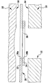
- FIG. 1 shows a section through a combustion chamber opening having a region of the cylinder head gasket and the built-in cylinder head gasket of these adjacent areas of the engine block and the cylinder head, to improve the clarity of illustration, the various components were drawn at a distance from each other and the dimensions of the support plate and the metal ring were not reproduced to scale.
- the drawing shows an engine block 10 with a combustion chamber 12 and an engine block sealing surface 14, a cylinder head 16 with a cylinder head sealing surface 18 and a cylinder head gasket 20 (all only partially).
- the illustrated embodiment of the cylinder head gasket has a flat support plate 22 and - as shown - a sheet metal ring 24.
- the cylinder head gasket 20 has a designated as a whole 26 combustion chamber opening, which from an opening 26a in the support plate 22 and the opening 26b the sheet metal ring 24 is formed.
- the cylinder head gasket according to the invention need not be purely metallic and may be provided with one or more in particular elastomeric coatings and / or inserts, which were not shown in the drawing.
- the metal sheet ring 24 is substantially thinner than the carrier sheet 22 and is mounted on that side of the carrier sheet 22 which, when the cylinder head gasket is installed, faces the engine block 10.
- the sheet metal ring 24 may, as already mentioned, be connected to the carrier plate 22 by spot welding or by means of a continuous weld.
- the lower side of the sheet metal ring 24 according to the drawing can be provided with the above-described height profile, which is produced by embossing.
- the sheet metal ring 24 adjacent portion of the support plate 22 is provided with a height profile, before the sheet metal ring 24 secured to the support plate 22, said height profile provided on the side facing away from the sheet metal ring 24 of the support plate 22 should be.
- the sheet metal ring 24 directly adjoins the combustion chamber opening 26, although in principle it could have an opening 26b whose diameter is slightly larger than the diameter of the combustion chamber 12.
- the cylinder head gasket for sealing around a combustion chamber opening around several combustion chamber sealing elements although this is not desirable for cost reasons.
- the sheet metal rings are very thin - their thickness is between 0.05 mm and 0.40 mm, preferably of the order of 0.25 mm.
- the support plate is much thicker and has a thickness of up to 1.10 mm, preferably of about 0.40 mm.
Landscapes
- Engineering & Computer Science (AREA)
- General Engineering & Computer Science (AREA)
- Mechanical Engineering (AREA)
- Chemical & Material Sciences (AREA)
- Combustion & Propulsion (AREA)
- Gasket Seals (AREA)
Claims (6)
- Joint de culasse (20) pour un moteur à cylindres multiples, lequel présente une plaque d'étanchéité monocouche avec une unique couche de tôle métallique (22) s'étendant au moins sensiblement sur toute la plaque d'étanchéité, des ouvertures de chambre de combustion (26a, 26b) ainsi que, pour chaque ouverture de chambre de combustion, au moins un élément étanche de chambre de combustion de forme annulaire, qui renferme l'ouverture de chambre de combustion associée et a la configuration d'un anneau en tôle métallique (24) disposé sur la couche de tôle métallique et relié à celle-ci par liaison de matière par soudage,
dans lequel les anneaux en tôle métallique forment les uniques éléments étanches de chambre de combustion,
et le joint de culasse est sans moulure dans les zones des anneaux en tôle métallique,
dans lequel afin d'homogénéiser les forces de pression agissant sur le joint de culasse (20) installé autour des ouvertures de chambre de combustion (26a, 26b),- l'anneau en tôle métallique (24), sur son côté se détourner de la couche de tôle métallique (22)
ou- la zone, adjacente à l'anneau en tôle métallique (24), de la couche de tôle métallique (22) sur son côté se détourner de l'anneau en tôle métalliqueprésente autour de l'ouverture de chambre de combustion associée un profil en hauteur estampé,
dans lequel les anneaux en tôle métallique sont respectivement plus minces que la couche de tôle métallique, et
dans lequel tous les anneaux en tôle métallique sont installés sur le côté, tourné vers le bloc moteur lorsque le joint de culasse est monté, de la couche de tôle métallique. - Joint de culasse selon la revendication 1, dans lequel l'anneau en tôle métallique (24) jouxte directement l'ouverture de chambre de combustion (26a, 26b) associée à celui-ci.
- Joint de culasse selon la revendication 1 ou 2, dans lequel l'épaisseur des anneaux en tôle métallique (24) présente une valeur de 0,05 mm à 0,40 mm.
- Joint de culasse selon la revendication 3, dans lequel l'épaisseur des anneaux en tôle métallique présente une valeur d'environ 0,25 mm.
- Joint de culasse selon l'une quelconque des revendications 1 à 4, dans lequel l'épaisseur de la couche de tôle métallique (22) présente au maximum une valeur de 1,10 mm.
- Joint de culasse selon la revendication 5, dans lequel l'épaisseur de la couche de tôle métallique (22) présente une valeur d'environ 0,40 mm.
Applications Claiming Priority (2)
| Application Number | Priority Date | Filing Date | Title |
|---|---|---|---|
| DE102006040121 | 2006-08-26 | ||
| DE102006055741A DE102006055741A1 (de) | 2006-08-26 | 2006-11-25 | Zylinderkopfdichtung |
Publications (2)
| Publication Number | Publication Date |
|---|---|
| EP1892441A1 EP1892441A1 (fr) | 2008-02-27 |
| EP1892441B1 true EP1892441B1 (fr) | 2019-05-29 |
Family
ID=38800752
Family Applications (1)
| Application Number | Title | Priority Date | Filing Date |
|---|---|---|---|
| EP07015424.0A Active EP1892441B1 (fr) | 2006-08-26 | 2007-08-07 | Joint de tête de cylindre |
Country Status (3)
| Country | Link |
|---|---|
| US (1) | US8100411B2 (fr) |
| EP (1) | EP1892441B1 (fr) |
| DE (1) | DE102006055741A1 (fr) |
Families Citing this family (2)
| Publication number | Priority date | Publication date | Assignee | Title |
|---|---|---|---|---|
| US9970548B2 (en) | 2013-03-14 | 2018-05-15 | Federal-Mogul Llc | Multi-layer gasket |
| EP3008363A1 (fr) | 2013-06-10 | 2016-04-20 | Federal-Mogul Corporation | Joint statique et son procédé de fabrication |
Family Cites Families (18)
| Publication number | Priority date | Publication date | Assignee | Title |
|---|---|---|---|---|
| JPS62155375A (ja) * | 1985-12-27 | 1987-07-10 | Nippon Metal Gasket Kk | 金属ガスケツト |
| DE3741344A1 (de) * | 1987-12-07 | 1989-06-15 | Yamaha Corp | Metalldichtung |
| EP0468526B1 (fr) * | 1990-07-26 | 1995-04-05 | Taiho Kogyo Co., Ltd. | Joint métallique |
| JP3135911B2 (ja) * | 1990-10-20 | 2001-02-19 | 大豊工業株式会社 | 金属ガスケットの製造方法 |
| DE4142600C2 (de) | 1991-12-21 | 1995-07-13 | Elringklinger Gmbh | Zylinderkopfdichtung |
| US5618049A (en) * | 1993-06-04 | 1997-04-08 | Japan Metal Gasket Co., Ltd. | Metallic gasket |
| US5582415A (en) * | 1993-08-31 | 1996-12-10 | Kokusan Parts Industry Co., Ltd. | Metal gasket |
| US5938208A (en) * | 1994-12-30 | 1999-08-17 | Kokusan Parts Industry Co., Ltd. | Separate plate placed between adjacent valve bodies in a control valve unit of an automatic transmission |
| DE19520695C1 (de) * | 1995-06-07 | 1996-07-04 | Elringklinger Gmbh | Metallische Zylinderkopfdichtung |
| DE29812037U1 (de) * | 1997-07-19 | 1998-09-24 | Elring Klinger GmbH, 72581 Dettingen | Zylinderkopfdichtung |
| JP3363781B2 (ja) * | 1998-03-18 | 2003-01-08 | 石川ガスケット株式会社 | 複数のシール部を有する金属板ガスケット |
| JP3057443B1 (ja) * | 1999-02-12 | 2000-06-26 | 石川ガスケット株式会社 | ボアリングを有する金属ガスケット |
| US6715770B2 (en) * | 1999-07-24 | 2004-04-06 | Federal-Mogul Sealing Systems Gmbh | Cylinder head gasket having a welded-on overlay |
| DE10021975A1 (de) * | 2000-05-05 | 2001-11-22 | Reinz Dichtungs Gmbh | Metallische Flachdichtung |
| JP2002054740A (ja) * | 2000-08-07 | 2002-02-20 | Ishikawa Gasket Co Ltd | 多気筒用のヘッドガスケット |
| US7200932B2 (en) * | 2004-01-13 | 2007-04-10 | Federal-Mogul Worldwide, Inc. | Laser welded multi-layered steel gasket assembly |
| DE102005012172B4 (de) * | 2004-11-05 | 2013-03-14 | Federal-Mogul Sealing Systems Gmbh | Flachdichtung |
| DE102004056638A1 (de) * | 2004-11-24 | 2006-10-12 | Federal-Mogul Sealing Systems Gmbh | Flachdichtung |
-
2006
- 2006-11-25 DE DE102006055741A patent/DE102006055741A1/de not_active Withdrawn
-
2007
- 2007-08-07 EP EP07015424.0A patent/EP1892441B1/fr active Active
- 2007-08-14 US US11/891,979 patent/US8100411B2/en active Active
Non-Patent Citations (1)
| Title |
|---|
| None * |
Also Published As
| Publication number | Publication date |
|---|---|
| US20080048401A1 (en) | 2008-02-28 |
| DE102006055741A1 (de) | 2008-02-28 |
| EP1892441A1 (fr) | 2008-02-27 |
| US8100411B2 (en) | 2012-01-24 |
Similar Documents
| Publication | Publication Date | Title |
|---|---|---|
| EP0747614B1 (fr) | Joint de culasse métallique | |
| DE3820796C2 (fr) | ||
| DE102008020277B4 (de) | Zylinderkopfdichtung | |
| EP1577590B1 (fr) | Joint de culasse | |
| EP1327799B1 (fr) | Joint de culasse pour la compensation de dépressions locales dans la zone du limiteur de compression | |
| DE20021017U1 (de) | Zylinderkopfdichtung | |
| DE60006435T2 (de) | Metallische Flachdichtung mit einem Ring in den Bohrungen | |
| EP1892441B1 (fr) | Joint de tête de cylindre | |
| DE10244853B4 (de) | Mehrlagige Zylinderkopfdichtung | |
| EP0769616B1 (fr) | Système d'étanchéité pour moteurs à combustion interne | |
| DE102010013545A1 (de) | Abgasstrang-Flachdichtung | |
| DE102008064044A1 (de) | Dichtsystem und Zylinderkopfdichtung für einen Hubkolben-Verbrennungsmotor | |
| DE19822143C9 (de) | Zylinderkopfdichtung | |
| EP2138745B1 (fr) | Joint de culasse | |
| DE19725986A1 (de) | Metallische Zylinderkopfdichtung | |
| WO2004081424A1 (fr) | Joint plat, en particulier joint de culasse | |
| DE19523825A1 (de) | Metallische Flachdichtung | |
| DE19749053C2 (de) | Metallische Zylinderkopfdichtung | |
| DE102013101253A1 (de) | Zylinderkopfdichtung | |
| DE10123487B4 (de) | Zylinderkopfdichtung für Motoren mit Zylinderbuchsen | |
| DE102013221784A1 (de) | Zylinderkopfdichtung | |
| EP1735553B1 (fr) | Joint de culasse metallique sans couche de separation | |
| DE29812037U1 (de) | Zylinderkopfdichtung | |
| DE19731132A1 (de) | Zylinderkopfdichtung | |
| DE19548574A1 (de) | Metallische Flachdichtung |
Legal Events
| Date | Code | Title | Description |
|---|---|---|---|
| PUAI | Public reference made under article 153(3) epc to a published international application that has entered the european phase |
Free format text: ORIGINAL CODE: 0009012 |
|
| AK | Designated contracting states |
Kind code of ref document: A1 Designated state(s): AT BE BG CH CY CZ DE DK EE ES FI FR GB GR HU IE IS IT LI LT LU LV MC MT NL PL PT RO SE SI SK TR |
|
| AX | Request for extension of the european patent |
Extension state: AL BA HR MK YU |
|
| 17P | Request for examination filed |
Effective date: 20080229 |
|
| AKX | Designation fees paid |
Designated state(s): AT BE BG CH CY CZ DE DK EE ES FI FR GB GR HU IE IS IT LI LT LU LV MC MT NL PL PT RO SE SI SK TR |
|
| 17Q | First examination report despatched |
Effective date: 20110117 |
|
| STAA | Information on the status of an ep patent application or granted ep patent |
Free format text: STATUS: EXAMINATION IS IN PROGRESS |
|
| GRAP | Despatch of communication of intention to grant a patent |
Free format text: ORIGINAL CODE: EPIDOSNIGR1 |
|
| STAA | Information on the status of an ep patent application or granted ep patent |
Free format text: STATUS: GRANT OF PATENT IS INTENDED |
|
| INTG | Intention to grant announced |
Effective date: 20190107 |
|
| GRAS | Grant fee paid |
Free format text: ORIGINAL CODE: EPIDOSNIGR3 |
|
| GRAA | (expected) grant |
Free format text: ORIGINAL CODE: 0009210 |
|
| STAA | Information on the status of an ep patent application or granted ep patent |
Free format text: STATUS: THE PATENT HAS BEEN GRANTED |
|
| AK | Designated contracting states |
Kind code of ref document: B1 Designated state(s): AT BE BG CH CY CZ DE DK EE ES FI FR GB GR HU IE IS IT LI LT LU LV MC MT NL PL PT RO SE SI SK TR |
|
| REG | Reference to a national code |
Ref country code: GB Ref legal event code: FG4D Free format text: NOT ENGLISH |
|
| REG | Reference to a national code |
Ref country code: CH Ref legal event code: EP |
|
| REG | Reference to a national code |
Ref country code: AT Ref legal event code: REF Ref document number: 1138454 Country of ref document: AT Kind code of ref document: T Effective date: 20190615 |
|
| REG | Reference to a national code |
Ref country code: DE Ref legal event code: R096 Ref document number: 502007016690 Country of ref document: DE |
|
| REG | Reference to a national code |
Ref country code: IE Ref legal event code: FG4D Free format text: LANGUAGE OF EP DOCUMENT: GERMAN |
|
| REG | Reference to a national code |
Ref country code: NL Ref legal event code: MP Effective date: 20190529 |
|
| REG | Reference to a national code |
Ref country code: LT Ref legal event code: MG4D |
|
| PG25 | Lapsed in a contracting state [announced via postgrant information from national office to epo] |
Ref country code: ES Free format text: LAPSE BECAUSE OF FAILURE TO SUBMIT A TRANSLATION OF THE DESCRIPTION OR TO PAY THE FEE WITHIN THE PRESCRIBED TIME-LIMIT Effective date: 20190529 Ref country code: LT Free format text: LAPSE BECAUSE OF FAILURE TO SUBMIT A TRANSLATION OF THE DESCRIPTION OR TO PAY THE FEE WITHIN THE PRESCRIBED TIME-LIMIT Effective date: 20190529 Ref country code: FI Free format text: LAPSE BECAUSE OF FAILURE TO SUBMIT A TRANSLATION OF THE DESCRIPTION OR TO PAY THE FEE WITHIN THE PRESCRIBED TIME-LIMIT Effective date: 20190529 Ref country code: PT Free format text: LAPSE BECAUSE OF FAILURE TO SUBMIT A TRANSLATION OF THE DESCRIPTION OR TO PAY THE FEE WITHIN THE PRESCRIBED TIME-LIMIT Effective date: 20190930 Ref country code: SE Free format text: LAPSE BECAUSE OF FAILURE TO SUBMIT A TRANSLATION OF THE DESCRIPTION OR TO PAY THE FEE WITHIN THE PRESCRIBED TIME-LIMIT Effective date: 20190529 |
|
| PG25 | Lapsed in a contracting state [announced via postgrant information from national office to epo] |
Ref country code: LV Free format text: LAPSE BECAUSE OF FAILURE TO SUBMIT A TRANSLATION OF THE DESCRIPTION OR TO PAY THE FEE WITHIN THE PRESCRIBED TIME-LIMIT Effective date: 20190529 Ref country code: BG Free format text: LAPSE BECAUSE OF FAILURE TO SUBMIT A TRANSLATION OF THE DESCRIPTION OR TO PAY THE FEE WITHIN THE PRESCRIBED TIME-LIMIT Effective date: 20190829 Ref country code: GR Free format text: LAPSE BECAUSE OF FAILURE TO SUBMIT A TRANSLATION OF THE DESCRIPTION OR TO PAY THE FEE WITHIN THE PRESCRIBED TIME-LIMIT Effective date: 20190830 |
|
| PG25 | Lapsed in a contracting state [announced via postgrant information from national office to epo] |
Ref country code: RO Free format text: LAPSE BECAUSE OF FAILURE TO SUBMIT A TRANSLATION OF THE DESCRIPTION OR TO PAY THE FEE WITHIN THE PRESCRIBED TIME-LIMIT Effective date: 20190529 Ref country code: CZ Free format text: LAPSE BECAUSE OF FAILURE TO SUBMIT A TRANSLATION OF THE DESCRIPTION OR TO PAY THE FEE WITHIN THE PRESCRIBED TIME-LIMIT Effective date: 20190529 Ref country code: NL Free format text: LAPSE BECAUSE OF FAILURE TO SUBMIT A TRANSLATION OF THE DESCRIPTION OR TO PAY THE FEE WITHIN THE PRESCRIBED TIME-LIMIT Effective date: 20190529 Ref country code: EE Free format text: LAPSE BECAUSE OF FAILURE TO SUBMIT A TRANSLATION OF THE DESCRIPTION OR TO PAY THE FEE WITHIN THE PRESCRIBED TIME-LIMIT Effective date: 20190529 Ref country code: DK Free format text: LAPSE BECAUSE OF FAILURE TO SUBMIT A TRANSLATION OF THE DESCRIPTION OR TO PAY THE FEE WITHIN THE PRESCRIBED TIME-LIMIT Effective date: 20190529 Ref country code: SK Free format text: LAPSE BECAUSE OF FAILURE TO SUBMIT A TRANSLATION OF THE DESCRIPTION OR TO PAY THE FEE WITHIN THE PRESCRIBED TIME-LIMIT Effective date: 20190529 |
|
| PG25 | Lapsed in a contracting state [announced via postgrant information from national office to epo] |
Ref country code: IT Free format text: LAPSE BECAUSE OF FAILURE TO SUBMIT A TRANSLATION OF THE DESCRIPTION OR TO PAY THE FEE WITHIN THE PRESCRIBED TIME-LIMIT Effective date: 20190529 |
|
| REG | Reference to a national code |
Ref country code: DE Ref legal event code: R097 Ref document number: 502007016690 Country of ref document: DE |
|
| PG25 | Lapsed in a contracting state [announced via postgrant information from national office to epo] |
Ref country code: TR Free format text: LAPSE BECAUSE OF FAILURE TO SUBMIT A TRANSLATION OF THE DESCRIPTION OR TO PAY THE FEE WITHIN THE PRESCRIBED TIME-LIMIT Effective date: 20190529 |
|
| PLBE | No opposition filed within time limit |
Free format text: ORIGINAL CODE: 0009261 |
|
| STAA | Information on the status of an ep patent application or granted ep patent |
Free format text: STATUS: NO OPPOSITION FILED WITHIN TIME LIMIT |
|
| GBPC | Gb: european patent ceased through non-payment of renewal fee |
Effective date: 20190829 |
|
| PG25 | Lapsed in a contracting state [announced via postgrant information from national office to epo] |
Ref country code: PL Free format text: LAPSE BECAUSE OF FAILURE TO SUBMIT A TRANSLATION OF THE DESCRIPTION OR TO PAY THE FEE WITHIN THE PRESCRIBED TIME-LIMIT Effective date: 20190529 |
|
| 26N | No opposition filed |
Effective date: 20200303 |
|
| PG25 | Lapsed in a contracting state [announced via postgrant information from national office to epo] |
Ref country code: LU Free format text: LAPSE BECAUSE OF NON-PAYMENT OF DUE FEES Effective date: 20190807 Ref country code: MC Free format text: LAPSE BECAUSE OF FAILURE TO SUBMIT A TRANSLATION OF THE DESCRIPTION OR TO PAY THE FEE WITHIN THE PRESCRIBED TIME-LIMIT Effective date: 20190529 Ref country code: SI Free format text: LAPSE BECAUSE OF FAILURE TO SUBMIT A TRANSLATION OF THE DESCRIPTION OR TO PAY THE FEE WITHIN THE PRESCRIBED TIME-LIMIT Effective date: 20190529 Ref country code: LI Free format text: LAPSE BECAUSE OF NON-PAYMENT OF DUE FEES Effective date: 20190831 Ref country code: CH Free format text: LAPSE BECAUSE OF NON-PAYMENT OF DUE FEES Effective date: 20190831 |
|
| REG | Reference to a national code |
Ref country code: BE Ref legal event code: MM Effective date: 20190831 |
|
| PG25 | Lapsed in a contracting state [announced via postgrant information from national office to epo] |
Ref country code: IE Free format text: LAPSE BECAUSE OF NON-PAYMENT OF DUE FEES Effective date: 20190807 |
|
| PG25 | Lapsed in a contracting state [announced via postgrant information from national office to epo] |
Ref country code: GB Free format text: LAPSE BECAUSE OF NON-PAYMENT OF DUE FEES Effective date: 20190829 Ref country code: BE Free format text: LAPSE BECAUSE OF NON-PAYMENT OF DUE FEES Effective date: 20190831 |
|
| REG | Reference to a national code |
Ref country code: AT Ref legal event code: MM01 Ref document number: 1138454 Country of ref document: AT Kind code of ref document: T Effective date: 20190807 |
|
| PG25 | Lapsed in a contracting state [announced via postgrant information from national office to epo] |
Ref country code: AT Free format text: LAPSE BECAUSE OF NON-PAYMENT OF DUE FEES Effective date: 20190807 |
|
| PG25 | Lapsed in a contracting state [announced via postgrant information from national office to epo] |
Ref country code: CY Free format text: LAPSE BECAUSE OF FAILURE TO SUBMIT A TRANSLATION OF THE DESCRIPTION OR TO PAY THE FEE WITHIN THE PRESCRIBED TIME-LIMIT Effective date: 20190529 |
|
| PG25 | Lapsed in a contracting state [announced via postgrant information from national office to epo] |
Ref country code: IS Free format text: LAPSE BECAUSE OF FAILURE TO SUBMIT A TRANSLATION OF THE DESCRIPTION OR TO PAY THE FEE WITHIN THE PRESCRIBED TIME-LIMIT Effective date: 20190929 |
|
| PG25 | Lapsed in a contracting state [announced via postgrant information from national office to epo] |
Ref country code: HU Free format text: LAPSE BECAUSE OF FAILURE TO SUBMIT A TRANSLATION OF THE DESCRIPTION OR TO PAY THE FEE WITHIN THE PRESCRIBED TIME-LIMIT; INVALID AB INITIO Effective date: 20070807 Ref country code: MT Free format text: LAPSE BECAUSE OF FAILURE TO SUBMIT A TRANSLATION OF THE DESCRIPTION OR TO PAY THE FEE WITHIN THE PRESCRIBED TIME-LIMIT Effective date: 20190529 |
|
| PGFP | Annual fee paid to national office [announced via postgrant information from national office to epo] |
Ref country code: FR Payment date: 20210823 Year of fee payment: 15 |
|
| P01 | Opt-out of the competence of the unified patent court (upc) registered |
Effective date: 20230512 |
|
| PG25 | Lapsed in a contracting state [announced via postgrant information from national office to epo] |
Ref country code: FR Free format text: LAPSE BECAUSE OF NON-PAYMENT OF DUE FEES Effective date: 20220831 |
|
| PGFP | Annual fee paid to national office [announced via postgrant information from national office to epo] |
Ref country code: DE Payment date: 20250819 Year of fee payment: 19 |