EP1892474A1 - Brûleur avec élément de protection pour électrodes d'allumage - Google Patents
Brûleur avec élément de protection pour électrodes d'allumage Download PDFInfo
- Publication number
- EP1892474A1 EP1892474A1 EP06017534A EP06017534A EP1892474A1 EP 1892474 A1 EP1892474 A1 EP 1892474A1 EP 06017534 A EP06017534 A EP 06017534A EP 06017534 A EP06017534 A EP 06017534A EP 1892474 A1 EP1892474 A1 EP 1892474A1
- Authority
- EP
- European Patent Office
- Prior art keywords
- burner
- ignition
- protective element
- ignition electrode
- electrode
- Prior art date
- Legal status (The legal status is an assumption and is not a legal conclusion. Google has not performed a legal analysis and makes no representation as to the accuracy of the status listed.)
- Withdrawn
Links
- 230000001681 protective effect Effects 0.000 claims abstract description 26
- 239000000463 material Substances 0.000 claims description 4
- 238000005452 bending Methods 0.000 abstract description 4
- 238000009434 installation Methods 0.000 abstract description 4
- 230000035939 shock Effects 0.000 abstract description 3
- 239000000446 fuel Substances 0.000 description 10
- VNWKTOKETHGBQD-UHFFFAOYSA-N methane Chemical compound C VNWKTOKETHGBQD-UHFFFAOYSA-N 0.000 description 6
- 238000002485 combustion reaction Methods 0.000 description 5
- 238000011161 development Methods 0.000 description 4
- 230000018109 developmental process Effects 0.000 description 4
- 239000007789 gas Substances 0.000 description 4
- 241001156002 Anthonomus pomorum Species 0.000 description 3
- 239000003345 natural gas Substances 0.000 description 3
- 229910000831 Steel Inorganic materials 0.000 description 2
- 230000001419 dependent effect Effects 0.000 description 2
- 238000010304 firing Methods 0.000 description 2
- 239000000203 mixture Substances 0.000 description 2
- 239000010959 steel Substances 0.000 description 2
- 230000002411 adverse Effects 0.000 description 1
- 239000002737 fuel gas Substances 0.000 description 1
- 239000000295 fuel oil Substances 0.000 description 1
- 239000007788 liquid Substances 0.000 description 1
- 239000002184 metal Substances 0.000 description 1
- 239000003208 petroleum Substances 0.000 description 1
- 238000005476 soldering Methods 0.000 description 1
- 238000010792 warming Methods 0.000 description 1
- 238000003466 welding Methods 0.000 description 1
Images


Classifications
-
- F—MECHANICAL ENGINEERING; LIGHTING; HEATING; WEAPONS; BLASTING
- F23—COMBUSTION APPARATUS; COMBUSTION PROCESSES
- F23Q—IGNITION; EXTINGUISHING-DEVICES
- F23Q9/00—Pilot flame igniters
-
- F—MECHANICAL ENGINEERING; LIGHTING; HEATING; WEAPONS; BLASTING
- F23—COMBUSTION APPARATUS; COMBUSTION PROCESSES
- F23Q—IGNITION; EXTINGUISHING-DEVICES
- F23Q3/00—Igniters using electrically-produced sparks
- F23Q3/006—Details
-
- F—MECHANICAL ENGINEERING; LIGHTING; HEATING; WEAPONS; BLASTING
- F23—COMBUSTION APPARATUS; COMBUSTION PROCESSES
- F23Q—IGNITION; EXTINGUISHING-DEVICES
- F23Q7/00—Incandescent ignition; Igniters using electrically-produced heat, e.g. lighters for cigarettes; Electrically-heated glowing plugs
- F23Q7/22—Details
- F23Q7/24—Safety arrangements
Definitions
- the invention relates to a burner with an igniter and at least one ignition electrode, in particular one for installation in a burner of a gas turbine.
- a designed as a pilot burner torch with a detonator and igniter leading ignition electrodes is, for example, in EP 0 193 838 B1 described.
- the detonator has the task of igniting the fuel.
- the ignition electrodes are attached to the outside of the pilot burner and run parallel to its longitudinal axis.
- the fuel supply is located inside the pilot burner and ends in fuel outlet openings.
- the ignition electrodes end in the region of the fuel outlet openings and ignite the fuel emerging there by means of a spark.
- the spark is generated by an ignition voltage between two ignition electrodes and is active during the entire ignition duration.
- Damage to or bending of one or both of the ignition electrodes mounted on the pilot burner during transport or installation may adversely affect the performance of the ignition electrodes. Damage or bending may therefore necessitate replacement of the ignition electrodes.
- the replacement of the ignition electrodes may also be necessary if one of the electrodes is so bent that, instead of between the electrode tips between an electrode line and another metallic component to the electric flashover and therefore the gas mixture can not be ignited.
- the invention has for its object to provide a burner with at least one ignition electrode available, in which the above problem does not occur or only to a reduced extent.
- the burner can be designed in particular as a pilot burner.
- the solution of the problem is that the burner is equipped with at least one extending on its outer side ignition electrode, said electrode is associated with a protective element which projects beyond the outside of the burner and beyond the ignition electrode.
- the advantage of the solution according to the invention is therefore that the ignition electrodes are protected and therefore damage during transport or when installing and removing the ignition electrodes can be avoided.
- the protective element is connected to the outside of the burner, so that the necessary stability is ensured.
- the protective element surrounds the ignition electrodes, wherein the ignition electrode is at least partially covered lengthwise, so that the at least one ignition electrode is optimally protected.
- the protective member may be U-shaped and fixed with the open side and the outside of the burner, so that the ignition electrode are protected from three sides to the outside.
- the protective element can completely enclose the electrodes at least in the front region near the electrode tips.
- the protective element may be formed by at least one rib, so that a better accessibility of the ignition electrodes is ensured.
- the rib can run parallel to the ignition electrode. There may also be at least one rib on each side of the ignition electrode.
- the protective element is made of a rigid and impact-resistant material, so that a deformation of the protective element, which could lead to a deformation of the internal ignition electrodes, is avoided.
- a further advantageous development is that the distance between the protective element and the ignition electrode is at least so great that when an ignition voltage applied to the ignition electrode no flashover between the protective element and the ignition electrode, so that a current flashover between the ignition electrode and the protective element can be reliably avoided ,
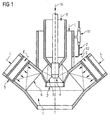
- the burner assembly shown in FIG 1 belongs to a gas turbine plant, the preferred field of application of the invention.
- the burner arrangement is, however, also suitable for gas-fired furnaces of boilers.
- the burner arrangement consists of at least one first burner 2 (not shown in FIG 1, see FIGS 2, 3), which serves as a pilot burner, and a second burner 1, which serves as a main burner and in the middle of the first burner 2 is used coaxially.
- the first burner 2 has a burner head 4 with a swirl blading 3 and can be operated with natural gas E and / or fuel oil H as fuel.
- the head 4 of the first burner 2 is coaxial with respect to the burner axis, surrounded by an air supply channel 6, which serves to supply the main portion of the combustion air L to a combustion zone (not shown) formed downstream of the burner head 4.
- the annular gap, the pressurized combustion air L is supplied from a compressor of the gas turbine plant. The hot fuel gases flow into the turbine blading.
- the main burner serving as the second burner 1 is supplemented by the first, serving as a pilot burner burner 2, i. In natural gas mode, it is possible to switch from pilot burner to main burner mode with its lower NOx values after starting up and warming up.
- the first burner 2 serves to stabilize the flame.
- the second burner comprises nozzle tubes 5 and an air supply channel 6.
- the nozzle tubes are connected to a fuel supply system (not shown) and serve to mix petroleum, natural gas or other gaseous or liquid fuel with the supplied combustion air L.
- the air supply channel 6 passes the combustion air L possibly with admixed fuel to the flame area.
- the ignition of the first burner 2 supplied air-fuel mixture via a rod or tubular electrode assembly with two ignition electrodes 7.
- the ignition electrodes 7 are mainly parallel to the axis of the first burner 2. In the region of the support plate 9 through which the ignition electrodes however, the distance of the ignition electrodes 7 from the outer wall of the first burner is significantly greater. The distance of the ignition electrodes 7 from each other is greater in the region of the support plate than in the region of the outer wall of the first burner 2.
- the ignition electrodes are fastened with connecting pieces 11 on the outside of the first burner 2.
- a burner 2 is shown as an exemplary embodiment of a burner according to the invention, on the outer wall of which two ignition electrodes 7 extending in the longitudinal direction of the burner 2 are mounted.
- the burner 2 can in particular serve as the first burner in the burner arrangement described with reference to FIG.
- the ignition electrodes of the burner 2 are covered by a protective element 8, which is formed in the present example as a U-shaped bent sheet 8.
- the legs of the sheet 8 each have an angled region in which they are attached to the outer wall of the burner 2.
- the attachment 10 is advantageously carried out by means of suitable detachable connecting elements, for example screws, so that, if necessary, access to the ignition electrodes 7 is possible.
- detachable connecting elements for example screws
- non-detachable connections are also possible instead of the detachable connection, for example welded connections.
- the U-shaped metal sheet extends at least over the front part of the ignition electrodes 7, ie the part which lies close to the electrode tips 12.
- the sheet 8 should be made of an impact resistant and rigid material such as e.g. Be made of steel.
- the distance of the sheet 8 from the ignition electrodes 7 should be at least so great that when a firing voltage applied to the ignition electrodes 7 no flashover between the fender 8 and the ignition electrodes 7 takes place.
- the concrete value for the distance depends on the dielectric strength of the medium between the electrodes 7 and the protective plate 8 as well as the geometry of the ignition electrodes and the temperature prevailing when the ignition voltage is applied. In the present embodiment with air as the medium, a safety distance of at least 5 mm should be maintained if the ignition voltage is 5 kV.
- FIG. 3 shows an ignition electrode 7 mounted in the burner 2 with two ignition electrodes 7 mounted on its outer wall.
- This burner 2 can also be used, in particular, as the first burner in the burner arrangement described with reference to FIG.
- the longitudinal ribs 8 project from the surface of the burner 2 via the ignition electrodes 7, so that the ignition electrodes 7 are protected from shocks.
- the ribs 8 are fixedly connected to the wall of the burner 2.
- the attachment 10 can be made for example by welding or soldering. Although detachable connections between the longitudinal ribs 8 and the burner 2, for example by means of screws, are also possible, non-detachable connections are completely sufficient since the arrangement does not substantially restrict access to the ignition electrodes 7 and the ribs 8 are therefore accessible the electrodes 7 need not be removed.
- the ribs 8 should be made of a shock-resistant and rigid material such as steel.
- the distance of the ribs from the ignition electrodes 7 should be at least at a starting voltage of 5 kV 5 mm so that no flashover between a firing electrode and a rib can take place.
Landscapes
- Engineering & Computer Science (AREA)
- Chemical & Material Sciences (AREA)
- Combustion & Propulsion (AREA)
- Mechanical Engineering (AREA)
- General Engineering & Computer Science (AREA)
- Gas Burners (AREA)
- Spark Plugs (AREA)
- Measuring Oxygen Concentration In Cells (AREA)
- Investigating, Analyzing Materials By Fluorescence Or Luminescence (AREA)
Priority Applications (13)
| Application Number | Priority Date | Filing Date | Title |
|---|---|---|---|
| EP06017534A EP1892474A1 (fr) | 2006-08-23 | 2006-08-23 | Brûleur avec élément de protection pour électrodes d'allumage |
| PT07788421T PT2054669E (pt) | 2006-08-23 | 2007-08-14 | Queimador com um elemento de segurança para eléctrodos de ignição |
| RU2009110175/06A RU2439433C2 (ru) | 2006-08-23 | 2007-08-14 | Горелка газовой турбины и газовая турбина |
| AT07788421T ATE462933T1 (de) | 2006-08-23 | 2007-08-14 | Brenner mit einem schutzelement für zündelektroden |
| ES07788421T ES2342500T3 (es) | 2006-08-23 | 2007-08-14 | Quemador con un elemento protector para electrodo de ignicion. |
| US12/310,284 US8327616B2 (en) | 2006-08-23 | 2007-08-14 | Burner having a protective element for ignition electrodes |
| KR1020097005879A KR101391212B1 (ko) | 2006-08-23 | 2007-08-14 | 점화 전극용 보호 요소를 구비한 버너 |
| PCT/EP2007/058411 WO2008022948A1 (fr) | 2006-08-23 | 2007-08-14 | brûleur doté d'un élément de projection pour des électrodes d'allumage |
| JP2009525023A JP2010501767A (ja) | 2006-08-23 | 2007-08-14 | 点火電極の保護要素を備えたバーナ |
| DE502007003342T DE502007003342D1 (de) | 2006-08-23 | 2007-08-14 | Brenner mit einem schutzelement für zündelektroden |
| EP07788421A EP2054669B1 (fr) | 2006-08-23 | 2007-08-14 | Bruleur dote d'un element de protection pour des electrodes d'allumage |
| CN2007800289382A CN101501401B (zh) | 2006-08-23 | 2007-08-14 | 具有点火极保护件的燃烧器 |
| JP2011281519A JP5484436B2 (ja) | 2006-08-23 | 2011-12-22 | 点火電極の保護要素を備えたバーナ |
Applications Claiming Priority (1)
| Application Number | Priority Date | Filing Date | Title |
|---|---|---|---|
| EP06017534A EP1892474A1 (fr) | 2006-08-23 | 2006-08-23 | Brûleur avec élément de protection pour électrodes d'allumage |
Publications (1)
| Publication Number | Publication Date |
|---|---|
| EP1892474A1 true EP1892474A1 (fr) | 2008-02-27 |
Family
ID=37606836
Family Applications (2)
| Application Number | Title | Priority Date | Filing Date |
|---|---|---|---|
| EP06017534A Withdrawn EP1892474A1 (fr) | 2006-08-23 | 2006-08-23 | Brûleur avec élément de protection pour électrodes d'allumage |
| EP07788421A Active EP2054669B1 (fr) | 2006-08-23 | 2007-08-14 | Bruleur dote d'un element de protection pour des electrodes d'allumage |
Family Applications After (1)
| Application Number | Title | Priority Date | Filing Date |
|---|---|---|---|
| EP07788421A Active EP2054669B1 (fr) | 2006-08-23 | 2007-08-14 | Bruleur dote d'un element de protection pour des electrodes d'allumage |
Country Status (11)
| Country | Link |
|---|---|
| US (1) | US8327616B2 (fr) |
| EP (2) | EP1892474A1 (fr) |
| JP (2) | JP2010501767A (fr) |
| KR (1) | KR101391212B1 (fr) |
| CN (1) | CN101501401B (fr) |
| AT (1) | ATE462933T1 (fr) |
| DE (1) | DE502007003342D1 (fr) |
| ES (1) | ES2342500T3 (fr) |
| PT (1) | PT2054669E (fr) |
| RU (1) | RU2439433C2 (fr) |
| WO (1) | WO2008022948A1 (fr) |
Cited By (1)
| Publication number | Priority date | Publication date | Assignee | Title |
|---|---|---|---|---|
| US8564276B2 (en) | 2008-11-21 | 2013-10-22 | Siemens Aktiengesellschaft | Method and measurement device for determining a condition of an electric igniter of a gas turbine burner and an ignition device for a gas turbine burner |
Families Citing this family (5)
| Publication number | Priority date | Publication date | Assignee | Title |
|---|---|---|---|---|
| EP2012060A1 (fr) * | 2007-07-03 | 2009-01-07 | Siemens Aktiengesellschaft | Fixation à trois points d'électrodes d'allumage d'un brûleur |
| GB2489963B (en) * | 2011-04-13 | 2015-11-04 | Rolls Royce Plc | Fuel injector arrangement having an igniter |
| RU2493489C2 (ru) * | 2011-07-28 | 2013-09-20 | Общество с ограниченной ответственностью "Энерго Эстейт" | Способ безопасной работы горелки в широком диапазоне нагрузок |
| CN109595587B (zh) * | 2017-09-30 | 2024-01-16 | 宁波方太厨具有限公司 | 一种点火针及应用有该点火针的燃气燃烧器 |
| CN109838816B (zh) * | 2017-11-29 | 2023-11-17 | 宁波方太厨具有限公司 | 一种燃气灶点火针及安装有该点火针的燃烧器 |
Citations (7)
| Publication number | Priority date | Publication date | Assignee | Title |
|---|---|---|---|---|
| US2850084A (en) * | 1954-03-19 | 1958-09-02 | Robertshaw Fulton Coutrols Com | Electric ignition device for gaseous fuel |
| US3823345A (en) * | 1971-01-19 | 1974-07-09 | J Willson | Electric igniter construction |
| US4029936A (en) * | 1975-01-13 | 1977-06-14 | The Tappan Company | Igniter assembly |
| EP0193838A2 (fr) * | 1985-03-04 | 1986-09-10 | Siemens Aktiengesellschaft | Disposition de brûleur pour installations de combustion, en particulier pour chambres de combustion d'installations de turbines à gaz ainsi que procédé de sa mise en oeuvre |
| US5856651A (en) * | 1998-04-06 | 1999-01-05 | Surface Igniter Corporation | Shield for a hot surface ignitor and method for fabricating a shield |
| US5860804A (en) * | 1997-10-30 | 1999-01-19 | Societe En Commandite Gaz Metropolitain | Baffle ignitor assembly |
| US6777650B1 (en) * | 2000-02-04 | 2004-08-17 | Saint-Gobtain Industrial Ceramics, Inc. | Igniter shields |
Family Cites Families (15)
| Publication number | Priority date | Publication date | Assignee | Title |
|---|---|---|---|---|
| FR1592091A (fr) * | 1968-02-27 | 1970-05-11 | ||
| JPS5130904U (fr) * | 1974-08-28 | 1976-03-05 | ||
| JPS5130904A (ja) * | 1974-09-09 | 1976-03-16 | Seiko Koki Kk | Dokimootaatonishosarerudenjikudosochi |
| JPS5257106U (fr) * | 1975-10-23 | 1977-04-25 | ||
| JPS5257106A (en) * | 1975-11-06 | 1977-05-11 | Shiyouji Nanba | Stable high concentrated liquid alminium alkolate composition with easy handling |
| US4149373A (en) * | 1977-08-29 | 1979-04-17 | United Technologies Corporation | Combustion chamber stress reducing means |
| DE3536198A1 (de) * | 1985-10-10 | 1987-04-16 | Webasto Werk Baier Kg W | Zuendfunkengeber fuer brennstoffbetriebenes heizgeraet |
| EP0228091A3 (fr) * | 1986-01-03 | 1988-08-24 | A/S Kongsberg Väpenfabrikk | Brûleur compact dans le sens axial pour une turbine à gaz et procédé pour le refroidir |
| US4903476A (en) * | 1988-12-27 | 1990-02-27 | General Electric Company | Gas turbine igniter with ball-joint support |
| US5393224A (en) * | 1993-12-02 | 1995-02-28 | American Standard Inc. | Ignitor assembly for power burner furnace |
| US5465571A (en) * | 1993-12-21 | 1995-11-14 | United Technologies Corporation | Fuel nozzle attachment in gas turbine combustors |
| US5802859A (en) * | 1996-12-16 | 1998-09-08 | Hudson Technologies, Inc. | Apparatus for recovering and analyzing volatile refrigerants |
| JP3875395B2 (ja) * | 1998-03-24 | 2007-01-31 | 財団法人石油産業活性化センター | 触媒燃焼装置 |
| CN100510538C (zh) * | 2003-08-22 | 2009-07-08 | 株式会社能率 | 点火装置 |
| DE202004006644U1 (de) * | 2004-04-27 | 2004-08-26 | Buderus Heiztechnik Gmbh | Elektrode |
-
2006
- 2006-08-23 EP EP06017534A patent/EP1892474A1/fr not_active Withdrawn
-
2007
- 2007-08-14 WO PCT/EP2007/058411 patent/WO2008022948A1/fr not_active Ceased
- 2007-08-14 CN CN2007800289382A patent/CN101501401B/zh active Active
- 2007-08-14 ES ES07788421T patent/ES2342500T3/es active Active
- 2007-08-14 KR KR1020097005879A patent/KR101391212B1/ko active Active
- 2007-08-14 JP JP2009525023A patent/JP2010501767A/ja active Pending
- 2007-08-14 RU RU2009110175/06A patent/RU2439433C2/ru active
- 2007-08-14 DE DE502007003342T patent/DE502007003342D1/de active Active
- 2007-08-14 AT AT07788421T patent/ATE462933T1/de active
- 2007-08-14 US US12/310,284 patent/US8327616B2/en active Active
- 2007-08-14 EP EP07788421A patent/EP2054669B1/fr active Active
- 2007-08-14 PT PT07788421T patent/PT2054669E/pt unknown
-
2011
- 2011-12-22 JP JP2011281519A patent/JP5484436B2/ja active Active
Patent Citations (7)
| Publication number | Priority date | Publication date | Assignee | Title |
|---|---|---|---|---|
| US2850084A (en) * | 1954-03-19 | 1958-09-02 | Robertshaw Fulton Coutrols Com | Electric ignition device for gaseous fuel |
| US3823345A (en) * | 1971-01-19 | 1974-07-09 | J Willson | Electric igniter construction |
| US4029936A (en) * | 1975-01-13 | 1977-06-14 | The Tappan Company | Igniter assembly |
| EP0193838A2 (fr) * | 1985-03-04 | 1986-09-10 | Siemens Aktiengesellschaft | Disposition de brûleur pour installations de combustion, en particulier pour chambres de combustion d'installations de turbines à gaz ainsi que procédé de sa mise en oeuvre |
| US5860804A (en) * | 1997-10-30 | 1999-01-19 | Societe En Commandite Gaz Metropolitain | Baffle ignitor assembly |
| US5856651A (en) * | 1998-04-06 | 1999-01-05 | Surface Igniter Corporation | Shield for a hot surface ignitor and method for fabricating a shield |
| US6777650B1 (en) * | 2000-02-04 | 2004-08-17 | Saint-Gobtain Industrial Ceramics, Inc. | Igniter shields |
Cited By (1)
| Publication number | Priority date | Publication date | Assignee | Title |
|---|---|---|---|---|
| US8564276B2 (en) | 2008-11-21 | 2013-10-22 | Siemens Aktiengesellschaft | Method and measurement device for determining a condition of an electric igniter of a gas turbine burner and an ignition device for a gas turbine burner |
Also Published As
| Publication number | Publication date |
|---|---|
| EP2054669B1 (fr) | 2010-03-31 |
| CN101501401A (zh) | 2009-08-05 |
| WO2008022948A1 (fr) | 2008-02-28 |
| CN101501401B (zh) | 2011-01-26 |
| KR101391212B1 (ko) | 2014-05-02 |
| ES2342500T3 (es) | 2010-07-07 |
| JP2010501767A (ja) | 2010-01-21 |
| RU2009110175A (ru) | 2010-09-27 |
| US20110120077A1 (en) | 2011-05-26 |
| JP2012107624A (ja) | 2012-06-07 |
| RU2439433C2 (ru) | 2012-01-10 |
| US8327616B2 (en) | 2012-12-11 |
| PT2054669E (pt) | 2010-04-21 |
| JP5484436B2 (ja) | 2014-05-07 |
| KR20090048508A (ko) | 2009-05-13 |
| DE502007003342D1 (de) | 2010-05-12 |
| ATE462933T1 (de) | 2010-04-15 |
| EP2054669A1 (fr) | 2009-05-06 |
Similar Documents
| Publication | Publication Date | Title |
|---|---|---|
| DE102011055241B4 (de) | Einrichtung und Verfahren zum Zünden einer Brennkammeranordnung | |
| EP2054669B1 (fr) | Bruleur dote d'un element de protection pour des electrodes d'allumage | |
| EP1754002B1 (fr) | Brûleur étagé à prémélange comprenant in injecteur de carburant liquide | |
| DE1201122B (de) | Flammenzuendeinrichtung fuer die Brennkammer einer Gasturbinenanlage | |
| CH697703B1 (de) | Kraftstoffdüsenanordnung. | |
| DE102004041272B4 (de) | Hybridbrennerlanze | |
| DE602004000485T2 (de) | Nachverbrennungsvorrichtung | |
| EP2092245B1 (fr) | Brûleur pour turbine à gaz avec un écran thermique pour l'alimentation de combustible | |
| EP2037173B1 (fr) | Tête de brûleur et procédé de combustion à un étage de combustible dans une zone de combustion éloignée de la tête de brûleur | |
| EP2236934A1 (fr) | Agencement de brûleur | |
| DE3238206A1 (de) | Zuendeinrichtung fuer kohlenstaubfeuerungen | |
| DE102009013664A1 (de) | System zum Einleiten von Kraftstoffen in den Abgasstrang eines Kraftfahrzeugs und Kraftstoffverdampfer hierfür | |
| DE811056C (de) | Brennkammeranordnung fuer fluessige Brennstoffe fuer Brennkraftturbinen | |
| EP2422136B1 (fr) | Brûleur à prémélange | |
| DE4446609A1 (de) | Verfahren und Vorrichtung zur Brennstoffzuführung zu einem sowohl für flüssige als auch für gasförmige Brennstoffe geeigneten Brenner | |
| DE102004030790B4 (de) | Zündkerze mit Zündkabel | |
| DE882775C (de) | Zuendeinrichtung fuer Gasturbinentriebwerke | |
| CH688525A5 (de) | Brenneranordnung. | |
| AT395761B (de) | Brenner | |
| DE19741508A1 (de) | Mischeinrichtung | |
| EP2048440B1 (fr) | Brûleur | |
| DE102007025761B4 (de) | Flammrohr | |
| DE29901832U1 (de) | Flammenüberwachungs- und Zündeinrichtung | |
| DE102022117210A1 (de) | Vorrichtung zur Bereitstellung einer elektrischen Gas- oder Funkenentladung und Verfahren zur Zündung eines Brenners | |
| DE3911924A1 (de) | Duese, insbesondere mit piezoelektrischer zuendung, und zuendmodul mit einer solchen duese |
Legal Events
| Date | Code | Title | Description |
|---|---|---|---|
| PUAI | Public reference made under article 153(3) epc to a published international application that has entered the european phase |
Free format text: ORIGINAL CODE: 0009012 |
|
| AK | Designated contracting states |
Kind code of ref document: A1 Designated state(s): AT BE BG CH CY CZ DE DK EE ES FI FR GB GR HU IE IS IT LI LT LU LV MC NL PL PT RO SE SI SK TR |
|
| AX | Request for extension of the european patent |
Extension state: AL BA HR MK YU |
|
| 17P | Request for examination filed |
Effective date: 20080411 |
|
| 17Q | First examination report despatched |
Effective date: 20080520 |
|
| AKX | Designation fees paid |
Designated state(s): AT BE BG CH CY CZ DE DK EE ES FI FR GB GR HU IE IS IT LI LT LU LV MC NL PL PT RO SE SI SK TR |
|
| STAA | Information on the status of an ep patent application or granted ep patent |
Free format text: STATUS: THE APPLICATION IS DEEMED TO BE WITHDRAWN |
|
| 18D | Application deemed to be withdrawn |
Effective date: 20101110 |