EP1892492A2 - Heat exchange module, in particular for an automobile vehicle, comprising a main radiator and a secondary radiator, and system comprising this module - Google Patents
Heat exchange module, in particular for an automobile vehicle, comprising a main radiator and a secondary radiator, and system comprising this module Download PDFInfo
- Publication number
- EP1892492A2 EP1892492A2 EP07110096A EP07110096A EP1892492A2 EP 1892492 A2 EP1892492 A2 EP 1892492A2 EP 07110096 A EP07110096 A EP 07110096A EP 07110096 A EP07110096 A EP 07110096A EP 1892492 A2 EP1892492 A2 EP 1892492A2
- Authority
- EP
- European Patent Office
- Prior art keywords
- main
- heat exchanger
- radiator
- heat exchange
- heat
- Prior art date
- Legal status (The legal status is an assumption and is not a legal conclusion. Google has not performed a legal analysis and makes no representation as to the accuracy of the status listed.)
- Withdrawn
Links
Images




Classifications
-
- F—MECHANICAL ENGINEERING; LIGHTING; HEATING; WEAPONS; BLASTING
- F28—HEAT EXCHANGE IN GENERAL
- F28F—DETAILS OF HEAT-EXCHANGE AND HEAT-TRANSFER APPARATUS, OF GENERAL APPLICATION
- F28F21/00—Constructions of heat-exchange apparatus characterised by the selection of particular materials
- F28F21/06—Constructions of heat-exchange apparatus characterised by the selection of particular materials of plastics material
- F28F21/067—Details
-
- F—MECHANICAL ENGINEERING; LIGHTING; HEATING; WEAPONS; BLASTING
- F02—COMBUSTION ENGINES; HOT-GAS OR COMBUSTION-PRODUCT ENGINE PLANTS
- F02B—INTERNAL-COMBUSTION PISTON ENGINES; COMBUSTION ENGINES IN GENERAL
- F02B29/00—Engines characterised by provision for charging or scavenging not provided for in groups F02B25/00, F02B27/00 or F02B33/00 - F02B39/00; Details thereof
- F02B29/04—Cooling of air intake supply
- F02B29/045—Constructional details of the heat exchangers, e.g. pipes, plates, ribs, insulation, materials, or manufacturing and assembly
- F02B29/0456—Air cooled heat exchangers
-
- F—MECHANICAL ENGINEERING; LIGHTING; HEATING; WEAPONS; BLASTING
- F02—COMBUSTION ENGINES; HOT-GAS OR COMBUSTION-PRODUCT ENGINE PLANTS
- F02B—INTERNAL-COMBUSTION PISTON ENGINES; COMBUSTION ENGINES IN GENERAL
- F02B29/00—Engines characterised by provision for charging or scavenging not provided for in groups F02B25/00, F02B27/00 or F02B33/00 - F02B39/00; Details thereof
- F02B29/04—Cooling of air intake supply
- F02B29/045—Constructional details of the heat exchangers, e.g. pipes, plates, ribs, insulation, materials, or manufacturing and assembly
- F02B29/0475—Constructional details of the heat exchangers, e.g. pipes, plates, ribs, insulation, materials, or manufacturing and assembly the intake air cooler being combined with another device, e.g. heater, valve, compressor, filter or EGR cooler, or being assembled on a special engine location
-
- F—MECHANICAL ENGINEERING; LIGHTING; HEATING; WEAPONS; BLASTING
- F28—HEAT EXCHANGE IN GENERAL
- F28D—HEAT-EXCHANGE APPARATUS, NOT PROVIDED FOR IN ANOTHER SUBCLASS, IN WHICH THE HEAT-EXCHANGE MEDIA DO NOT COME INTO DIRECT CONTACT
- F28D1/00—Heat-exchange apparatus having stationary conduit assemblies for one heat-exchange medium only, the media being in contact with different sides of the conduit wall, in which the other heat-exchange medium is a large body of fluid, e.g. domestic or motor car radiators
- F28D1/02—Heat-exchange apparatus having stationary conduit assemblies for one heat-exchange medium only, the media being in contact with different sides of the conduit wall, in which the other heat-exchange medium is a large body of fluid, e.g. domestic or motor car radiators with heat-exchange conduits immersed in the body of fluid
- F28D1/04—Heat-exchange apparatus having stationary conduit assemblies for one heat-exchange medium only, the media being in contact with different sides of the conduit wall, in which the other heat-exchange medium is a large body of fluid, e.g. domestic or motor car radiators with heat-exchange conduits immersed in the body of fluid with tubular conduits
- F28D1/0408—Multi-circuit heat exchangers, e.g. integrating different heat exchange sections in the same unit or heat exchangers for more than two fluids
- F28D1/0417—Multi-circuit heat exchangers, e.g. integrating different heat exchange sections in the same unit or heat exchangers for more than two fluids with particular circuits for the same heat exchange medium, e.g. with the heat exchange medium flowing through sections having different heat exchange capacities or for heating/cooling the heat exchange medium at different temperatures
-
- F—MECHANICAL ENGINEERING; LIGHTING; HEATING; WEAPONS; BLASTING
- F28—HEAT EXCHANGE IN GENERAL
- F28D—HEAT-EXCHANGE APPARATUS, NOT PROVIDED FOR IN ANOTHER SUBCLASS, IN WHICH THE HEAT-EXCHANGE MEDIA DO NOT COME INTO DIRECT CONTACT
- F28D1/00—Heat-exchange apparatus having stationary conduit assemblies for one heat-exchange medium only, the media being in contact with different sides of the conduit wall, in which the other heat-exchange medium is a large body of fluid, e.g. domestic or motor car radiators
- F28D1/02—Heat-exchange apparatus having stationary conduit assemblies for one heat-exchange medium only, the media being in contact with different sides of the conduit wall, in which the other heat-exchange medium is a large body of fluid, e.g. domestic or motor car radiators with heat-exchange conduits immersed in the body of fluid
- F28D1/04—Heat-exchange apparatus having stationary conduit assemblies for one heat-exchange medium only, the media being in contact with different sides of the conduit wall, in which the other heat-exchange medium is a large body of fluid, e.g. domestic or motor car radiators with heat-exchange conduits immersed in the body of fluid with tubular conduits
- F28D1/0408—Multi-circuit heat exchangers, e.g. integrating different heat exchange sections in the same unit or heat exchangers for more than two fluids
- F28D1/0426—Multi-circuit heat exchangers, e.g. integrating different heat exchange sections in the same unit or heat exchangers for more than two fluids with units having particular arrangement relative to the large body of fluid, e.g. with interleaved units or with adjacent heat exchange units in common air flow or with units extending at an angle to each other or with units arranged around a central element
- F28D1/0435—Combination of units extending one behind the other
-
- F—MECHANICAL ENGINEERING; LIGHTING; HEATING; WEAPONS; BLASTING
- F28—HEAT EXCHANGE IN GENERAL
- F28F—DETAILS OF HEAT-EXCHANGE AND HEAT-TRANSFER APPARATUS, OF GENERAL APPLICATION
- F28F1/00—Tubular elements; Assemblies of tubular elements
- F28F1/10—Tubular elements and assemblies thereof with means for increasing heat-transfer area, e.g. with fins, with projections, with recesses
- F28F1/12—Tubular elements and assemblies thereof with means for increasing heat-transfer area, e.g. with fins, with projections, with recesses the means being only outside the tubular element
- F28F1/126—Tubular elements and assemblies thereof with means for increasing heat-transfer area, e.g. with fins, with projections, with recesses the means being only outside the tubular element consisting of zig-zag shaped fins
-
- F—MECHANICAL ENGINEERING; LIGHTING; HEATING; WEAPONS; BLASTING
- F28—HEAT EXCHANGE IN GENERAL
- F28F—DETAILS OF HEAT-EXCHANGE AND HEAT-TRANSFER APPARATUS, OF GENERAL APPLICATION
- F28F1/00—Tubular elements; Assemblies of tubular elements
- F28F1/10—Tubular elements and assemblies thereof with means for increasing heat-transfer area, e.g. with fins, with projections, with recesses
- F28F1/12—Tubular elements and assemblies thereof with means for increasing heat-transfer area, e.g. with fins, with projections, with recesses the means being only outside the tubular element
- F28F1/24—Tubular elements and assemblies thereof with means for increasing heat-transfer area, e.g. with fins, with projections, with recesses the means being only outside the tubular element and extending transversely
- F28F1/32—Tubular elements and assemblies thereof with means for increasing heat-transfer area, e.g. with fins, with projections, with recesses the means being only outside the tubular element and extending transversely the means having portions engaging further tubular elements
- F28F1/325—Fins with openings
-
- F—MECHANICAL ENGINEERING; LIGHTING; HEATING; WEAPONS; BLASTING
- F28—HEAT EXCHANGE IN GENERAL
- F28F—DETAILS OF HEAT-EXCHANGE AND HEAT-TRANSFER APPARATUS, OF GENERAL APPLICATION
- F28F27/00—Control arrangements or safety devices specially adapted for heat-exchange or heat-transfer apparatus
- F28F27/02—Control arrangements or safety devices specially adapted for heat-exchange or heat-transfer apparatus for controlling the distribution of heat-exchange media between different channels
-
- F—MECHANICAL ENGINEERING; LIGHTING; HEATING; WEAPONS; BLASTING
- F28—HEAT EXCHANGE IN GENERAL
- F28F—DETAILS OF HEAT-EXCHANGE AND HEAT-TRANSFER APPARATUS, OF GENERAL APPLICATION
- F28F9/00—Casings; Header boxes; Auxiliary supports for elements; Auxiliary members within casings
- F28F9/26—Arrangements for connecting different sections of heat-exchange elements, e.g. of radiators
-
- F—MECHANICAL ENGINEERING; LIGHTING; HEATING; WEAPONS; BLASTING
- F01—MACHINES OR ENGINES IN GENERAL; ENGINE PLANTS IN GENERAL; STEAM ENGINES
- F01P—COOLING OF MACHINES OR ENGINES IN GENERAL; COOLING OF INTERNAL-COMBUSTION ENGINES
- F01P3/00—Liquid cooling
- F01P3/18—Arrangements or mounting of liquid-to-air heat-exchangers
- F01P2003/187—Arrangements or mounting of liquid-to-air heat-exchangers arranged in series
-
- F—MECHANICAL ENGINEERING; LIGHTING; HEATING; WEAPONS; BLASTING
- F01—MACHINES OR ENGINES IN GENERAL; ENGINE PLANTS IN GENERAL; STEAM ENGINES
- F01P—COOLING OF MACHINES OR ENGINES IN GENERAL; COOLING OF INTERNAL-COMBUSTION ENGINES
- F01P2060/00—Cooling circuits using auxiliaries
- F01P2060/02—Intercooler
-
- F—MECHANICAL ENGINEERING; LIGHTING; HEATING; WEAPONS; BLASTING
- F01—MACHINES OR ENGINES IN GENERAL; ENGINE PLANTS IN GENERAL; STEAM ENGINES
- F01P—COOLING OF MACHINES OR ENGINES IN GENERAL; COOLING OF INTERNAL-COMBUSTION ENGINES
- F01P2060/00—Cooling circuits using auxiliaries
- F01P2060/04—Lubricant cooler
-
- F—MECHANICAL ENGINEERING; LIGHTING; HEATING; WEAPONS; BLASTING
- F01—MACHINES OR ENGINES IN GENERAL; ENGINE PLANTS IN GENERAL; STEAM ENGINES
- F01P—COOLING OF MACHINES OR ENGINES IN GENERAL; COOLING OF INTERNAL-COMBUSTION ENGINES
- F01P2060/00—Cooling circuits using auxiliaries
- F01P2060/08—Cabin heater
-
- F—MECHANICAL ENGINEERING; LIGHTING; HEATING; WEAPONS; BLASTING
- F01—MACHINES OR ENGINES IN GENERAL; ENGINE PLANTS IN GENERAL; STEAM ENGINES
- F01P—COOLING OF MACHINES OR ENGINES IN GENERAL; COOLING OF INTERNAL-COMBUSTION ENGINES
- F01P2060/00—Cooling circuits using auxiliaries
- F01P2060/14—Condenser
-
- F—MECHANICAL ENGINEERING; LIGHTING; HEATING; WEAPONS; BLASTING
- F01—MACHINES OR ENGINES IN GENERAL; ENGINE PLANTS IN GENERAL; STEAM ENGINES
- F01P—COOLING OF MACHINES OR ENGINES IN GENERAL; COOLING OF INTERNAL-COMBUSTION ENGINES
- F01P2060/00—Cooling circuits using auxiliaries
- F01P2060/16—Outlet manifold
-
- F—MECHANICAL ENGINEERING; LIGHTING; HEATING; WEAPONS; BLASTING
- F28—HEAT EXCHANGE IN GENERAL
- F28D—HEAT-EXCHANGE APPARATUS, NOT PROVIDED FOR IN ANOTHER SUBCLASS, IN WHICH THE HEAT-EXCHANGE MEDIA DO NOT COME INTO DIRECT CONTACT
- F28D21/00—Heat-exchange apparatus not covered by any of the groups F28D1/00 - F28D20/00
- F28D2021/0019—Other heat exchangers for particular applications; Heat exchange systems not otherwise provided for
- F28D2021/008—Other heat exchangers for particular applications; Heat exchange systems not otherwise provided for for vehicles
- F28D2021/0084—Condensers
-
- F—MECHANICAL ENGINEERING; LIGHTING; HEATING; WEAPONS; BLASTING
- F28—HEAT EXCHANGE IN GENERAL
- F28D—HEAT-EXCHANGE APPARATUS, NOT PROVIDED FOR IN ANOTHER SUBCLASS, IN WHICH THE HEAT-EXCHANGE MEDIA DO NOT COME INTO DIRECT CONTACT
- F28D21/00—Heat-exchange apparatus not covered by any of the groups F28D1/00 - F28D20/00
- F28D2021/0019—Other heat exchangers for particular applications; Heat exchange systems not otherwise provided for
- F28D2021/008—Other heat exchangers for particular applications; Heat exchange systems not otherwise provided for for vehicles
- F28D2021/0089—Oil coolers
-
- F—MECHANICAL ENGINEERING; LIGHTING; HEATING; WEAPONS; BLASTING
- F28—HEAT EXCHANGE IN GENERAL
- F28D—HEAT-EXCHANGE APPARATUS, NOT PROVIDED FOR IN ANOTHER SUBCLASS, IN WHICH THE HEAT-EXCHANGE MEDIA DO NOT COME INTO DIRECT CONTACT
- F28D21/00—Heat-exchange apparatus not covered by any of the groups F28D1/00 - F28D20/00
- F28D2021/0019—Other heat exchangers for particular applications; Heat exchange systems not otherwise provided for
- F28D2021/008—Other heat exchangers for particular applications; Heat exchange systems not otherwise provided for for vehicles
- F28D2021/0091—Radiators
- F28D2021/0094—Radiators for recooling the engine coolant
-
- F—MECHANICAL ENGINEERING; LIGHTING; HEATING; WEAPONS; BLASTING
- F28—HEAT EXCHANGE IN GENERAL
- F28F—DETAILS OF HEAT-EXCHANGE AND HEAT-TRANSFER APPARATUS, OF GENERAL APPLICATION
- F28F9/00—Casings; Header boxes; Auxiliary supports for elements; Auxiliary members within casings
- F28F9/02—Header boxes; End plates
- F28F2009/0285—Other particular headers or end plates
- F28F2009/0287—Other particular headers or end plates having passages for different heat exchange media
-
- F—MECHANICAL ENGINEERING; LIGHTING; HEATING; WEAPONS; BLASTING
- F28—HEAT EXCHANGE IN GENERAL
- F28F—DETAILS OF HEAT-EXCHANGE AND HEAT-TRANSFER APPARATUS, OF GENERAL APPLICATION
- F28F2215/00—Fins
- F28F2215/12—Fins with U-shaped slots for laterally inserting conduits
-
- Y—GENERAL TAGGING OF NEW TECHNOLOGICAL DEVELOPMENTS; GENERAL TAGGING OF CROSS-SECTIONAL TECHNOLOGIES SPANNING OVER SEVERAL SECTIONS OF THE IPC; TECHNICAL SUBJECTS COVERED BY FORMER USPC CROSS-REFERENCE ART COLLECTIONS [XRACs] AND DIGESTS
- Y02—TECHNOLOGIES OR APPLICATIONS FOR MITIGATION OR ADAPTATION AGAINST CLIMATE CHANGE
- Y02T—CLIMATE CHANGE MITIGATION TECHNOLOGIES RELATED TO TRANSPORTATION
- Y02T10/00—Road transport of goods or passengers
- Y02T10/10—Internal combustion engine [ICE] based vehicles
- Y02T10/12—Improving ICE efficiencies
Definitions
- each exchanger is fixed. It corresponds to the beam surface of the exchanger.
- the only possibility of adjusting the cooling of the exchanger is the starting or stopping of the circulation pump of the cooling fluid. Such a system therefore offers little adaptability to the load conditions of the engine.
- the invention also makes it possible different configurations of the thermal energy management system that adapt to different load conditions of the vehicle engine.
- one of the secondary heat exchangers is connected in series with a condenser forming part of an air conditioning circuit of the passenger compartment of the motor vehicle.
- the circulation of the coolant in the heat exchange module 2 of Figure 1 is carried out as follows.
- the hot fluid of the main circuit, or high temperature circuit enters the main radiator 196 through the inlet pipe 26 of the main inlet chamber, as shown schematically by the arrow 44, passes through the tubes 12 of the bundle connected to the main inlet chamber 16 and enters the main outlet chamber 22.
- the cooled heat transfer fluid exits the main outlet chamber 22 through the pipe 30, as shown by the arrow 46.
- FIG. 5 shows a fifth variant embodiment of a heat exchange module 2 according to the present invention.
- This embodiment is similar to the embodiment of Figure 4 in the sense that the outlet manifold of the main heat exchanger 4 does not have a partition wall which divides it into a main exit chamber and a chamber. secondary output. The interior volume of this box is therefore one piece. The circulation of the coolant in the main heat exchanger 4 is therefore performed in the same manner as in the embodiment shown in FIG. 4.
- main radiator 196 constitutes a common part to the main network 180 and the secondary network 182.
- FIG. 21 The system of FIG. 21 is close to that of FIG. 15, but the loops associated with the radiators 196 and 200 are interconnected solely by a common expansion vessel 216. This is connected to the two loops by two pipes 218. and 220 which open respectively upstream of the pumps 188 and 199. As in the case of Figures 19 and 20, the radiators 196 and 200 do not communicate with each other through a through hole 32.
Landscapes
- Engineering & Computer Science (AREA)
- Physics & Mathematics (AREA)
- Thermal Sciences (AREA)
- Mechanical Engineering (AREA)
- General Engineering & Computer Science (AREA)
- Geometry (AREA)
- Chemical & Material Sciences (AREA)
- Combustion & Propulsion (AREA)
- Heat-Exchange Devices With Radiators And Conduit Assemblies (AREA)
- Details Of Heat-Exchange And Heat-Transfer (AREA)
- Devices That Are Associated With Refrigeration Equipment (AREA)
- Cooling, Air Intake And Gas Exhaust, And Fuel Tank Arrangements In Propulsion Units (AREA)
Abstract
Description
L'invention se rapporte au domaine des échangeurs de chaleur, notamment pour véhicules automobiles, et en particulier aux modules d'échange de chaleur constitués de plusieurs échangeurs de chaleur superposés pour constituer un ensemble unique.The invention relates to the field of heat exchangers, especially for motor vehicles, and in particular heat exchange modules consisting of several superimposed heat exchangers to form a single set.
Plus précisément, l'invention concerne un module d'échange de chaleur comprenant un échangeur de chaleur principal et au moins un échangeur de chaleur secondaire possédant chacun une boîte collectrice d'entrée, une boîte collectrice de sortie, un faisceau de tubes dans lesquels circule un fluide caloporteur, et des surfaces d'échange en relation d'échange thermique avec les tubes du faisceau, l'échangeur principal et l'échangeur secondaire étant disposés de manière que leur faisceau de tubes soit traversé par un même flux d'air.More specifically, the invention relates to a heat exchange module comprising a main heat exchanger and at least one secondary heat exchanger each having an inlet manifold, an outlet manifold, a bundle of tubes in which circulates a heat transfer fluid, and exchange surfaces in heat exchange relationship with the tubes of the bundle, the main heat exchanger and the secondary heat exchanger being arranged so that their bundle of tubes is traversed by the same air flow.
Les échangeurs de chaleur pour véhicules automobiles se présentent généralement sous la forme d'un faisceau de tubes de circulation de fluide et de surfaces d'échange de chaleur avec le milieu extérieur, telles que des ailettes ou des intercalaires ondulés. Le faisceau est interposé entre deux boîtes collectrices qui distribuent le fluide dans les tubes de circulation. Ou bien, en variante, l'échangeur comporte une boîte collectrice unique divisée en une section d'entrée et une section de sortie.Motor vehicle heat exchangers are generally in the form of a bundle of fluid circulation tubes and heat exchange surfaces with the external medium, such as fins or corrugated inserts. The beam is interposed between two manifolds that distribute the fluid in the circulation tubes. Alternatively, the exchanger has a single header divided into an inlet section and an outlet section.
Il est connu d'assembler sur un échangeur principal, tel qu'un radiateur de refroidissement d'un moteur de véhicule automobile, un ou plusieurs échangeurs secondaires afin de constituer un ensemble, appelé encore module, prêt à être installé dans le véhicule, les surfaces d'échange de chaleur du module pouvant être communes aux différents échangeurs. L'échangeur secondaire est constitué le plus souvent d'un refroidisseur d'air de suralimentation du moteur, d'un condenseur de climatisation ou d'un radiateur d'huile.It is known to assemble on one main exchanger, such as a cooling radiator of a motor vehicle engine, one or more secondary exchangers to form an assembly, called still module, ready to be installed in the vehicle, the heat exchange surfaces of the module that can be common to the different exchangers. The secondary exchanger is most often an engine cooler air cooler, an air conditioning condenser or an oil cooler.
Dans les modules d'échange de chaleur de ce type, chaque échangeur possède son propre circuit de circulation de fluide dans lequel circule un fluide caloporteur particulier. Ceci se traduit par une multiplication des canalisations nécessaires. En outre, il est nécessaire d'amener les différents fluides de refroidissement en face avant du véhicule pour réaliser un échange de chaleur avec l'air atmosphérique ambiant. Les échangeurs sont donc fréquemment éloignés des équipements qu'ils refroidissent, ce qui se traduit par une longueur importante des canalisations et des difficultés pour aménager un passage sous le capot du véhicule pour ces canalisations, compte tenu de l'espace limité disponible.In heat exchange modules of this type, each exchanger has its own fluid circulation circuit in which circulates a particular heat transfer fluid. This results in a multiplication of the necessary pipelines. In addition, it is necessary to bring the different cooling fluids to the front of the vehicle to achieve a heat exchange with the ambient air. The exchangers are therefore frequently removed from the equipment they cool, which results in a significant length of pipes and difficulties to arrange a passage under the hood of the vehicle for these pipes, given the limited space available.
En outre, la surface d'échange de chaleur de chaque échangeur est fixe. Elle correspond à la surface du faisceau de l'échangeur. La seule possibilité d'ajustement du refroidissement de l'échangeur est la mise en marche ou l'arrêt de la pompe de circulation du fluide de refroidissement. Un tel système offre donc peu d'adaptabilité aux conditions de charge du moteur.In addition, the heat exchange surface of each exchanger is fixed. It corresponds to the beam surface of the exchanger. The only possibility of adjusting the cooling of the exchanger is the starting or stopping of the circulation pump of the cooling fluid. Such a system therefore offers little adaptability to the load conditions of the engine.
La présente invention a par conséquent pour objet un module d'échange de chaleur et un système de gestion de l'énergie thermique développée par le moteur du véhicule qui remédie à ces inconvénients.The present invention therefore relates to a heat exchange module and a thermal energy management system developed by the vehicle engine that overcomes these disadvantages.
Ces buts sont atteints, conformément à l'invention, par le fait que le même fluide caloporteur circule dans l'échangeur de chaleur principal et dans l'échangeur de chaleur secondaire.These objects are achieved in accordance with the invention by the fact that the same heat transfer fluid circulates in the main heat exchanger and in the secondary heat exchanger.
On obtient ainsi un composant que l'on peut appeler "multi-échangeur" qui comporte deux échangeurs de chaleur formant un ensemble mécanique unitaire, par exemple grâce à des boites collectrices communes, des intercalaires communs, des joues communes ou autres moyens de connexion entre les faiceaux respectifs des échangeurs. Toutefois, le module de l'invention a cette particularité que c'est le même fluide caloporteur qui circule dans les deux échangeurs de chaleur, ledit fluide pouvant être à deux températures différentes car provenant, par exemple, de deux boucles de circulation de fluide distinctes, comme évoqué plus loin.This gives a component that can be called "multi-exchanger" which comprises two heat exchangers forming a unitary mechanical unit, for example by means of common collecting boxes, common dividers, common cheeks or other means of connection between the respective creeks of the exchangers. However, the module of the invention has this feature that it is the same coolant circulating in the two heat exchangers, said fluid which can be at two different temperatures because of, for example, two separate fluid circulation loops, as discussed below.
Ainsi, chaque échangeur pourra présenter au moins une entrée et au moins une sortie pour le fluide. Les tubes de l'un des faisceaux pourront par ailleurs être de caractéristiques identiques d'un échangeur à l'autre, au moins en ce qui concerne les tubes des échangeurs dans lesquels circulent le même fluide.Thus, each exchanger may have at least one inlet and at least one outlet for the fluid. The tubes of one of the beams may also be of identical characteristics from one exchanger to another, at least as regards the tubes of the exchangers in which the same fluid flows.
Selon un mode de réalisation particulier, les surfaces d'échanges avec l'air, aussi appelées faisceaux, seront sensiblement identiques d'un échangeur à l'autre, au moins en ce qui concerne les échangeurs dans lesquels circulent le même fluide.According to a particular embodiment, the air exchange surfaces, also called beams, will be substantially identical from one exchanger to the other, at least as regards the exchangers in which the same fluid circulates.
Dans une forme de réalisation préférentielle, la boîte collectrice de sortie de l'échangeur principal communique avec la boîte collectrice d'entrée de l'échangeur secondaire par un orifice de passage.In a preferred embodiment, the outlet manifold of the main heat exchanger communicates with the inlet manifold of the secondary heat exchanger via a through orifice.
De préférence, le module d'échange de chaleur comporte une cloison de partition qui divise la boîte collectrice de sortie de l'échangeur principal en une chambre de sortie principale et en une chambre de sortie secondaire, les tubes du faisceau de l'échangeur principal raccordés à la chambre de sortie principale, ainsi que la partie de la boîte collectrice d'entrée de l'échangeur principal raccordée à ces mêmes tubes constituant un radiateur principal, les tubes du faisceau de l'échangeur principal raccordés à la chambre de sortie secondaire, ainsi que la partie de la boîte collectrice d'entrée de l'échangeur principal raccordée à ces mêmes tubes et l'échangeur secondaire constituant un radiateur secondaire.Preferably, the heat exchange module comprises a partition wall which divides the outlet manifold of the main exchanger into a main outlet chamber and a secondary outlet chamber, the main exchanger beam tubes. connected to the main outlet chamber, as well as the portion of the main heat exchanger inlet manifold connected to these same tubes constituting a main radiator, the tubes of the main heat exchanger bundle connected to the secondary outlet chamber , as well as the portion of the inlet manifold of the main exchanger connected to these same tubes and the secondary exchanger constituting a secondary radiator.
Grâce à ces caractéristiques, on peut faire circuler le même fluide caloporteur dans tout ou partie des échangeurs. Il est possible de sélectionner la partie du faisceau dans laquelle circule le fluide. L'invention permet également de réaliser différentes configurations du système de gestion de l'énergie thermique qui s'adaptent aux différentes conditions de charge du moteur du véhicule.Thanks to these characteristics, it is possible to circulate the same coolant in all or part of the exchangers. It is possible to select the part of the beam in which the fluid flows. The invention also makes it possible different configurations of the thermal energy management system that adapt to different load conditions of the vehicle engine.
La surface d'échange du radiateur secondaire peut être augmentée de la partie du faisceau du radiateur principal qui communique avec l'échangeur secondaire. On obtient ainsi un radiateur secondaire de plus grande dimension, sans augmentation de l'encombrement facial du module d'échange puisque les deux échangeurs peuvent être superposés l'un à l'autre.The exchange surface of the secondary radiator can be increased by the portion of the main radiator beam that communicates with the secondary heat exchanger. This produces a secondary radiator of larger size, without increasing the bulk of the exchange module since the two heat exchangers can be superimposed on one another.
De préférence, le module comporte des moyens de commutation qui permettent d'ouvrir et de fermer l'orifice de passage entre la boîte collectrice de sortie de l'échangeur principal et la boite collectrice d'entrée de l'échangeur secondaire.Preferably, the module comprises switching means that open and close the passage opening between the outlet manifold of the main exchanger and the inlet manifold of the secondary exchanger.
La mise en oeuvre de ces moyens de commutation permet de faire varier la surface du faisceau de l'échangeur, et par conséquent sa capacité de refroidissement. Dans une réalisation particulière, les moyens de commutation sont constitués par un piston relié par une tige à un organe de commande.The implementation of these switching means makes it possible to vary the surface area of the heat exchanger bundle, and consequently its cooling capacity. In a particular embodiment, the switching means consist of a piston connected by a rod to a control member.
L'organe de commande peut tirer ou pousser le piston pour fermer l'orifice de passage.The controller can pull or push the piston to close the passage opening.
Dans une réalisation particulière, le module comporte une tubulure d'entrée raccordée à la boîte collectrice d'entrée de l'échangeur principal, cette tubulure unique servant à l'entrée commune du fluide caloporteur dans le radiateur principal et dans le radiateur secondaire.In a particular embodiment, the module comprises an inlet pipe connected to the inlet manifold of the main heat exchanger, this single pipe serving for the common inlet of the coolant in the main radiator and in the secondary radiator.
Selon une autre réalisation, le module comporte une cloison de partition située entre la partie de la boite collectrice d'entrée faisant partie du radiateur principal et la partie de la boîte collectrice d'entrée faisant partie du radiateur secondaire, cette cloison divisant la boîte collectrice de l'échangeur principal en une chambre d'entrée principale et en une chambre d'entrée secondaire, une tubulure d'entrée étant raccordée à la chambre d'entrée principale pour l'entrée du fluide caloporteur dans le radiateur principal et une autre tubulure d'entrée étant raccordée à la chambre d'entrée secondaire pour l'entrée du fluide caloporteur dans le radiateur secondaire.In another embodiment, the module comprises a partition wall located between the portion of the inlet header box forming part of the main radiator and the portion of the inlet header box forming part of the secondary radiator, this partition dividing the header from the main exchanger into a main entrance chamber and into a secondary inlet chamber, an inlet manifold being connected to the main inlet chamber for the coolant inlet into the main radiator and another inlet manifold connected to the secondary inlet chamber for inlet of the coolant in the secondary radiator.
Le module d'échange de chaleur peut comporter au moins un troisième échangeur appartenant à un circuit de refroidissement séparé dans lequel circule un fluide de cycle différent du fluide caloporteur de l'échangeur principal et de l'échangeur secondaire.The heat exchange module may comprise at least a third exchanger belonging to a separate cooling circuit in which circulates a different cycle fluid of the coolant of the main exchanger and the secondary exchanger.
Dans une telle configuration, le module pourra conserver la structure d'un "multi-échangeur", c'est-à-dire, un module comportant plusieurs échangeurs de chaleur formant un ensemble mécanique unitaire, par exemple grâce à des boîtes collectrices communes, des intercalaires communs, des joue communes ou autres moyens de connexion entre les faiceaux respectifs des échangeursIn such a configuration, the module may retain the structure of a "multi-exchanger", that is to say, a module comprising a plurality of heat exchangers forming a unitary mechanical unit, for example by means of common manifolds, common spacers, common cheeks or other means of connection between the respective clusters of the exchangers
Dans une réalisation particulière, les boîtes collectrices de l'échangeur principal et/ou de l'échangeur secondaire sont divisées en plusieurs chambres par des cloisons de séparation, de manière à définir une série de passes pour le fluide caloporteur.In a particular embodiment, the manifolds of the main exchanger and / or the secondary exchanger are divided into several chambers by partition walls, so as to define a series of passes for the coolant.
Les surfaces d'échange peuvent être constituées par des ailettes de refroidissement communes aux échangeurs du module. Les surfaces d'échange peuvent également être constituées par des intercalaires ondulés communs aux échangeurs du module.The exchange surfaces may be constituted by cooling fins common to the exchangers of the module. The exchange surfaces may also be constituted by corrugated inserts common to the exchangers of the module.
Dans l'un comme l'autre cas, elles pourront être équipées de moyens de rupture du pont thermique entre les échangeurs, ceci afin d'éviter les difficultés pouvant provenir de la circulation dans ceux-ci d'un fluide à différents niveaux de température d'un échangeur à l'autre.In either case, they may be equipped with means for breaking the thermal bridge between the exchangers, in order to avoid the difficulties that may arise from the circulation therein of a fluid at different temperature levels. from one exchanger to another.
Les surfaces d'échange peuvent être assemblées aux tubes des échangeurs par brasage. Elles peuvent également être assemblées mécaniquement aux tubes des échangeurs.The exchange surfaces can be assembled to the tubes of solder exchangers. They can also be mechanically assembled to the tubes of the exchangers.
Dans une réalisation particulière, les boîtes collectrices des échangeurs sont constituées d'une plaque collectrice et d'un couvercle assemblés par brasage. Dans une autre réalisation, les boîtes collectrices des échangeurs sont constituées d'une plaque collectrice et d'un couvercle, notamment en matière plastique, fixé mécaniquement sur la plaque collectrice.In a particular embodiment, the manifolds of the exchangers consist of a collector plate and a lid assembled by brazing. In another embodiment, the manifolds of the exchangers consist of a header plate and a cover, in particular plastic, mechanically fixed on the header plate.
D'autre part, l'invention concerne un système de gestion de l'énergie thermique développée par un moteur thermique de véhicule automobile comprenant un réseau principal équipé d'une pompe principale pour faire circuler un fluide de cycle caloporteur entre le moteur thermique et un radiateur de refroidissement principal échangeant de la chaleur avec l'air atmosphérique, le réseau principal comprenant, en outre, une canalisation de court-circuit et une canalisation de chauffage comprenant un aérotherme, et un réseau secondaire incluant un radiateur secondaire et une pompe secondaire, dans lequel le réseau principal et le réseau secondaire sont reliés par des moyens d'intercommunication qui permettent de faire circuler de manière contrôlée le fluide caloporteur entre le réseau principal et le réseau secondaire ou d'interdire cette circulation en fonction de l'état de charge du moteur thermique, et dans lequel le radiateur principal et le radiateur secondaire font partie d'un module d'échange de chaleur tel que défini ci-dessus.On the other hand, the invention relates to a thermal energy management system developed by a motor vehicle engine comprising a main network equipped with a main pump for circulating a coolant cycle fluid between the engine and a heat pump. main cooling radiator exchanging heat with atmospheric air, the main network further comprising a short circuit line and a heating line comprising a heater, and a secondary network including a secondary radiator and a secondary pump, in which the main network and the secondary network are connected by intercommunication means which make it possible to circulate in a controlled manner the coolant between the main network and the secondary network or to prohibit this circulation as a function of the state of charge of the engine, and in which the main radiator and the secondary radiator are part of a heat exchange module as defined above.
Sous un autre aspect, l'invention concerne un module d'échange de chaleur comportant un échangeur principal et deux échangeurs secondaires, le même fluide circulant dans l'échangeur principal et les deux échangeurs secondaires.In another aspect, the invention relates to a heat exchange module comprising a main exchanger and two secondary exchangers, the same fluid flowing in the main exchanger and the two secondary exchangers.
L'invention concerne aussi un système de gestion de l'énergie thermique développée par un moteur thermique de véhicule automobile, comprenant un circuit à haute température équipé d'une pompe principale pour faire circuler un fluide caloporteur entre le moteur thermique et un échangeur principal à haute température échangeant de la chaleur avec l'air atmosphérique extérieur, le circuit à haute température comprenant en outre une canalisation de chauffage comportant un aérotherme, et un circuit à basse température incluant un échangeur secondaire et une pompe secondaire, dans lequel l'échangeur principal à haute température et l'échangeur secondaire font partie d'un module d'échange de chaleur, tel que défini précédement.The invention also relates to a thermal energy management system developed by a motor vehicle engine, comprising a high temperature circuit equipped with a main pump for circulating a heat transfer fluid between the heat engine and a heat exchanger primary heat exchanger with external atmospheric air, the high temperature circuit further comprising a heating pipe having a heater, and a low temperature circuit including a secondary heat exchanger and a secondary pump, wherein main exchanger at high temperature and the secondary exchanger are part of a heat exchange module, as defined above.
Dans une forme de réalisation, l'un des échangeurs secondaires est monté en série avec un condenseur faisant partie d'un circuit de climatisation de l'habitacle du véhicule automobile.In one embodiment, one of the secondary heat exchangers is connected in series with a condenser forming part of an air conditioning circuit of the passenger compartment of the motor vehicle.
On peut prévoir aussi que l'un des échangeurs secondaires est monté en série avec un refroidisseur d'air de suralimentation.It can also be provided that one of the secondary exchangers is mounted in series with a charge air cooler.
Dans une variante, l'échangeur secondaire monté en série avec le refroidisseur d'air de suralimentation et le refroidisseur d'air de suralimentation lui-même font partie du circuit à haute température.In a variant, the secondary heat exchanger connected in series with the charge air cooler and the charge air cooler itself is part of the high temperature circuit.
Dans une autre variante, l'échangeur secondaire monté en série avec le refroisseur d'air de suralimentation et le refroidisseur d'air de suralimentation lui-même font partie du circuit à basse température.In another variant, the secondary heat exchanger connected in series with the charge air cooler and the charge air cooler itself are part of the low temperature circuit.
D'autres caractéristiques et avantages de la présente invention apparaîtront encore à la lecture de la description qui suit d'exemples de réalisation donnés à titre illustratif en référence aux figures annexées. Sur ces figures :
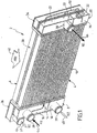
- la figure 1 est une vue en perspective d'une première variante d'un module d'échange de chaleur conforme à la présente invention ;
- la figure 2 est une vue en perspective d'une deuxième variantede réalisation d'un module d'échange de chaleur conforme à la présente invention ;
- la figure 3 est une vue en perspective d'une troisième variante d'un module d'échange de chaleur conforme à la présente invention ;
- la figure 4 est une vue en perspective d'une quatrième variante d'un module d'échange de chaleur conforme à la présente invention ;
- la figure 5 est une vue en perspective d'une cinquième variante d'un module d'échange de chaleur conforme à la présente invention ;
- la figure 6 illustre une première variante de moyens de commutation pour un module d'échange de chaleur selon l'une des figures 1 à 5 ;
- la figure 7 illustre une deuxième variante de moyens de commutation pour un module d'échange de chaleur selon l'une des figures 1 à 5 ;
- la figure 8 est une vue en plan d'une ailette brasée destinée à un module d'échange de chaleur conforme à la présente invention ;
- la figure 9 est une vue en coupe selon la ligne IX de la Figure 8 ;
- la figure 10 est une vue en coupe selon la ligne X de la Figure 8 ;
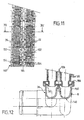
- les figures 11 et 12 illustrent un assemblage entièrement mécanique d'un module d'échange de chaleur conforme à la présente invention ;
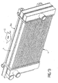
- la figure 13 représente un module d'échange de chaleur conforme à l'invention comportant un troisième échangeur ;
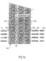
- la figure 14 est une vue en plan d'une ailette destinée au module d'échange de chaleur de la figure 13 ;
- la figure 15 illustre schématiquement un système de gestion de l'énergie thermique développée par un moteur thermique conforme à la présente invention;
- la figure 16 représente la configuration du système de la figure 15 en cas de démarrage à froid ;
- La figure 17 représente le système de gestion de l'énergie thermique de la figure 15 en configuration de faible charge ;
- la figure 18 illustre le système de gestion de l'énergie thermique de la figure 15 en configuration de forte charge ;
- les figures 19 à 22 illustrent schématiquement d'autres systèmes de gestion de l'énergie thermique conformes à la présente invention ;
- les figures 23 et 24 illustrent encore un autre mode de réalisation d'un système de gestion de l'énergie thermique développé par un moteur thermique conforme à la présente invention.
- Figure 1 is a perspective view of a first variant of a heat exchange module according to the present invention;
- Figure 2 is a perspective view of a second alternative embodiment of a heat exchange module according to the present invention;
- Figure 3 is a perspective view of a third variant of a heat exchange module according to the present invention;
- Figure 4 is a perspective view of a fourth variant of a heat exchange module according to the present invention;
- Figure 5 is a perspective view of a fifth variant of a heat exchange module according to the present invention;
- FIG. 6 illustrates a first variant of switching means for a heat exchange module according to one of FIGS. 1 to 5;
- FIG. 7 illustrates a second variant of switching means for a heat exchange module according to one of FIGS. 1 to 5;
- Figure 8 is a plan view of a brazed fin for a heat exchange module according to the present invention;
- Figure 9 is a sectional view along line IX of Figure 8;
- Figure 10 is a sectional view along line X of Figure 8;
- Figures 11 and 12 illustrate a fully mechanical assembly of a heat exchange module according to the present invention;
- FIG. 13 represents a heat exchange module according to the invention comprising a third exchanger;
- FIG. 14 is a plan view of a fin intended for heat exchange module of Figure 13;
- Figure 15 schematically illustrates a thermal energy management system developed by a heat engine according to the present invention;
- Figure 16 shows the configuration of the system of Figure 15 in case of cold start;
- Fig. 17 shows the thermal energy management system of Fig. 15 in low load configuration;
- Fig. 18 illustrates the thermal energy management system of Fig. 15 in high load configuration;
- Figures 19 to 22 schematically illustrate other thermal energy management systems according to the present invention;
- Figures 23 and 24 illustrate yet another embodiment of a thermal energy management system developed by a heat engine according to the present invention.
On a représenté sur la figure 1 un module d'échange de chaleur, désigné par la référence générale 2, conforme à la présente invention. Il est constitué de deux échangeurs, à savoir un échangeur de chaleur principal, désigné par la référence générale 4, et un échangeur de chaleur secondaire, désigné par la référence générale 6. L'échangeur de chaleur principal 4 est constitué d'une boîte collectrice d'entrée 8, d'une boîte collectrice de sortie 10 et d'un faisceau de tubes de circulation 12 interposé entre la boîte collectrice d'entrée 8 et la boîte collectrice de sortie 10. La boîte collectrice d'entrée 8 comporte une cloison de partition 14 qui la divise en une chambre d'entrée principale 16 et en une chambre d'entrée secondaire 18. De même, la boîte collectrice de sortie 10 comporte une cloison de partition 20 qui la divise en une chambre de sortie principale 22 et une chambre de sortie secondaire 24. Une tubulure d'entrée 26 est raccordée' à la chambre d'entrée 0principale 16 et une tubulure d'entrée 28 est raccordée à la chambre d'entrée secondaire 18.There is shown in Figure 1 a heat exchange module, designated by the
La tubulure 26 distribue le fluide caloporteur dans les tubes du faisceau 12 raccordés à la chambre d'entrée principale et la tubulure d'entrée 28 distribue le fluide caloporteur dans les tubes du faisceau 12 raccordés à la chambre d'entrée secondaire 18. La chambre de sortie principale 22 comporte une tubulure de sortie 30 qui permet la sortie du fluide caloporteur entré par la tubulure d'entrée 26 hors de la chambre de sortie principale 22. La chambre de sortie secondaire 24 ne comporte pas de tubulure de sortie, mais un orifice de passage 32 qui la met en communication avec une boîte collectrice d'entrée 34 de l'échangeur secondaire 6. Ce dernier possède par ailleurs une boîte collectrice de sortie 36 et un faisceau de tubes 38 interposé entre la boîte collectrice d'entrée 34 et la boîte collectrice de sortie 36. Une tubulure de sortie 40 est raccordée à la boîte collectrice de sortie 36. L'orifice de passage 32 peut être ouvert ou fermé à l'aide de moyens de commutation qui seront décrits ultérieurement.The
Le faisceau de tubes 12 de l'échangeur de chaleur principal 4 et le faisceau de tubes 38 de l'échangeur secondaire 6 sont traversés par un même flux d'air schématisé par la flèche 42. Les deux échangeurs sont disposés de telle manière que l'échangeur secondaire 6 est refroidi en premier par le flux d'air 42. Les tubes du faisceau 12 sont donc refroidis par un flux d'air qui s'est déjà réchauffé au contact des tubes du faisceau 38 de l'échangeur secondaire 6.The bundle of
La partie des tubes du faisceau 12 de l'échangeur principal 4 raccordée à la chambre principale d'entrée 16 et à la chambre de sortie principale 22 constitue, dans ce qui suit, un radiateur principal 196 (voir Figures 15 - 18). La partie des tubes du faisceau 12 de l'échangeur principal 4 raccordée à la chambre d'entrée secondaire 18 et à la chambre de sortie secondaire 24, en série avec le faisceau de tubes 38 de l'échangeur secondaire, constitue, dans ce qui suit, un radiateur secondaire 200 (voir Figures 15 - 18). Etant donné que la température du fluide caloporteur à la sortie du radiateur secondaire 200 est plus basse que la température de sortie de ce même fluide à la sortie du radiateur principal 196, le radiateur secondaire est également appelé dans ce qui suit radiateur à basse température (B.T.) et le radiateur principal radiateur à haute température (H.T.). Le module d'échange de chaleur 2 de l'invention peut ainsi générer deux niveaux de température, par exemple une haute température égale à environ 100°C et une basse température égale à environ 60°C. Le radiateur à haute température est destiné à faire partie d'un circuit à haute température et à refroidir le moteur thermique du véhicule automobile, ainsi que des équipements qui ne nécessitent pas d'être refroidis jusqu'à une température basse. Au contraire, le radiateur basse température est raccordé à un réseau dit à basse température et il est destiné au refroidissement de fluide pour lequel le niveau de température du circuit de refroidissement du moteur est trop élevé.The portion of the tubes of the
La circulation du fluide caloporteur dans le module d'échange de chaleur 2 de la Figure 1 s'effectue de la manière suivante. Le fluide chaud du circuit principal, ou circuit à haute température, pénètre dans le radiateur principal 196 par la tubulure d'entrée 26 de la chambre d'entrée principale, comme schématisé par la flèche 44, traverse les tubes 12 du faisceau raccordé à la chambre d'entrée principale 16 et pénètre dans la chambre de sortie principale 22. Le fluide caloporteur refroidi sort de la chambre de sortie principale 22 par la tubulure 30, comme schématisé par la flèche 46.The circulation of the coolant in the
Le fluide caloporteur chaud du circuit secondaire, ou circuit à basse température, pénètre dans la chambre d'entrée secondaire 18 par la tubulure d'entrée 28, comme schématisé par la flèche 48. Il parcourt la partie des tubes du faisceau 12 raccordée à la chambre d'entrée secondaire 18 et à la chambre de sortie secondaire 24. Il pénètre dans la chambre de sortie secondaire 24 et passe dans la boîte collectrice d'entrée 34 par l'orifice de passage 32, comme schématisé par les flèches 50. Le fluide parcourt alors les tubes du faisceau 38, de gauche à droite selon la figure, pour pénétrer dans la boîte collectrice de sortie 36. Le fluide caloporteur refroidi ressort par la tubulure de sortie 40, comme schématisé par la flèche 52. C'est le même fluide caloporteur qui circule dans le radiateur principal et dans le radiateur secondaire.The hot heat transfer fluid of the secondary circuit, or circuit at low temperature, enters the
On a représenté sur la figure 2 une vue en perspective d'une variante de réalisation du module d'échange de chaleur 2 de la Figure 1. Elle s'en distingue par le fait que la boîte collectrice d'entrée 8 de l'échangeur principal 4 comporte une tubulure d'entrée unique 26 au lieu des tubulures 26 et 28 du mode de réalisation de la Figure 1. En outre, la boîte collectrice d'entrée 8 ne comporte pas de cloison de partition 14. Son volume n'est par conséquent pas divisé en une chambre d'entrée principale 16 et une chambre d'entrée secondaire 18. La tubulure d'entrée 26 sert à la fois pour l'entrée du fluide caloporteur du réseau principal ou réseau à haute température et du fluide caloporteur du réseau secondaire ou réseau à basse température, comme schématisé par la flèche 44. Dans la boîte collectrice d'entrée 8, une partie du fluide pénètre dans les tubes du faisceau 12 raccordés à la chambre de sortie principale 22, et le reste du fluide pénètre dans la partie des tubes du faisceau 12 raccordée à la chambre de sortie secondaire 24.FIG. 2 shows a perspective view of an alternative embodiment of the
En revanche, la boîte collectrice de sortie 10 est divisée en une chambre de sortie principale 22 et une chambre de sortie secondaire par une cloison de partition 20, de la même manière que dans le mode de réalisation de la figure 1.On the other hand, the
On a représenté sur la figure 3 une variante de réalisation du module d'échange de chaleur de l'invention représenté sur la figure 2. Comme le mode de réalisation de la Figure 2, ce dernier comporte une tubulure d'entrée unique 26 raccordée à la boîte collectrice d'entrée 8 de l'échangeur principal 2. La différence entre les deux réalisations tient au fait que la boîte collectrice d'entrée 34 de l'échangeur secondaire 6 comporte une cloison de séparation 58 qui la divise en une chambre inférieure 60 et une chambre supérieure 62. De la même manière, la boite collectrice de sortie 36 de l'échangeur secondaire 6 comporte une cloison de séparation 64 qui la divise en une chambre inférieure 66 et une chambre supérieure 68.FIG. 3 shows an alternative embodiment of the heat exchange module of the invention shown in FIG. 2. Like the embodiment of FIG. 2, the latter comprises a
De la sorte, le fluide caloporteur circule dans les tubes du faisceau 38 de l'échangeur secondaire 6 en effectuant une série d'allers et retours entre la boîte collectrice d'entrée 34 et la boîte collectrice de sortie 36. Ces allers et retours sont appelés passes. Dans l'exemple représenté, il y a trois passes. Après avoir pénétré dans la chambre inférieure 60 par l'orifice de passage 32, comme schématisé par la flèche 70, le fluide circule de droite à gauche, selon la figure, pour pénétrer dans la chambre inférieure 66 de la boîte collectrice de sortie 36. Il se répartit dans cette chambre et circule, de gauche à droite selon la figure, dans les tubes du faisceau 38 pour parvenir dans la chambre supérieure 62 de la boîte collectrice d'entrée 34, puis circule à nouveau de droite à gauche selon la figure, comme schématisé par la flèche 74, pour pénétrer dans la chambre supérieure 68 de la boîte collectrice de sortie 36. Le fluide caloporteur froid quitte ensuite la chambre supérieure 68 par la tubulure de sortie 40, comme schématisé par la flèche 52.In this way, the heat transfer fluid circulates in the tubes of the
Dans l'exemple représenté, la circulation du fluide caloporteur dans le radiateur principal ou radiateur à haute température s'effectue en une seule passe. Toutefois, il va de soi que le radiateur principal pourrait également comporter des cloisons de séparation semblables aux cloisons 58 et 64 afin que la circulation du fluide s'effectue en plusieurs passes. De même, le radiateur secondaire pourrait comporter davantage de cloisons de séparation afin d'augmenter le nombre de passes.In the example shown, the circulation of the coolant in the main radiator or radiator at high temperature is carried out in a single pass. However, it goes without saying that the main radiator could also include partition walls similar to the
On a représenté sur la figure 4 une autre variante de réalisation d'un module d'échange de chaleur 2 conforme à la présente invention. Il se distingue des précédents, illustrés et décrits en référence aux figures 1 à 3, par le fait que la boîte collectrice de sortie 10 de l'échangeur de chaleur principal 4 ne comporte pas de cloison de partition qui divise son volume intérieur en deux chambres. En conséquence, le radiateur principal, ou radiateur à haute température 196, se confond avec l'échangeur de chaleur principal ou échangeur à haute température 4. De la même manière, le radiateur secondaire 200 se confond avec l'échangeur de chaleur secondaire 6.FIG. 4 shows another variant embodiment of a
La circulation du fluide dans ce module d'échange de chaleur s'effectue de la manière suivante. Le fluide caloporteur du circuit principal pénètre dans la boite collectrice d'entrée 8 de l'échangeur de chaleur principal 4 par la tubulure d'entrée 80, comme schématisé par la flèche 82. Il parcourt les tubes du faisceau 12, de gauche à droite selon la figure, pour parvenir dans la boîte collectrice de sortie 10 dont il ressort refroidi par la tubulure de sortie 84, comme schématisé par la flèche 86. Le fluide du circuit secondaire, ou circuit à basse température, pénètre dans la boîte collectrice 36 du radiateur secondaire par la tubulure 88, comme schématisé par la flèche 90, Il parcourt les tubes du faisceau 38, de gauche à droite selon la figure, pour pénétrer dans la boîte collectrice de sortie 34 et ressortir par la tubulure 92, comme schématisé par la flèche 94.The circulation of the fluid in this heat exchange module is carried out as follows. The heat transfer fluid of the main circuit enters the
Il peut ne pas y avoir d'orifice de passage entre le radiateur principal et le radiateur secondaire. Dans ce cas, la circulation de fluide entre le réseau principal et le réseau secondaire s'effectue par des moyens de communication externes au module d'échange de chaleur, comme des vannes. Le module d'échange de chaleur 2 de la Figure 4 peut également comporter un orifice de passage 32 mettant en communication la boîte collectrice de sortie 10 de l'échangeur de chaleur principal avec la boîte collectrice d'entrée 34 de l'échangeur de chaleur secondaire, comme représenté. L'orifice de passage 32 peut être ouvert ou fermé par des moyens de commutation qui seront décrits ultérieurement. Cette disposition permet de faire varier la capacité d'échange de l'échangeur en faisant circuler le fluide dans tout ou partie de ce dernier.There may be no through hole between the main radiator and the secondary radiator. In this case, the flow of fluid between the main network and the secondary network is effected by means of communication external to the heat exchange module, such as valves. The
On a représenté sur la figure 5 une cinquième variante de réalisation d'un module d'échange de chaleur 2 conforme à la présente invention. Ce mode de réalisation est semblable au mode de réalisation de la Figure 4 dans le sens où la boîte collectrice de sortie de l'échangeur de chaleur principal 4 ne comporte pas de cloison de partition qui la divise en une chambre de sortie principale et une chambre de sortie secondaire. Le volume intérieur de cette boite est donc d'une seule pièce. La circulation du fluide caloporteur dans l'échangeur de chaleur principal 4 s'effectue par conséquent de la même manière que dans le mode de réalisation représenté sur la Figure 4.FIG. 5 shows a fifth variant embodiment of a
La boîte collectrice de sortie 36 de l'échangeur de chaleur principal 6 comporte une cloison de séparation 96 qui la divise en une chambre inférieure 98 et une chambre supérieure 100. Le fluide caloporteur du circuit à basse température pénètre dans la chambre supérieure 100 par la tubulure d'entrée 102, comme représenté par la flèche 104. Il parcourt la partie supérieure des tubes du faisceau, située au-dessus de la cloison de séparation 96, de gauche à droite selon la figure, pour parvenir dans la boîte collectrice 34 et se répartir dans cette dernière, comme schématisé par la flèche 106, puis il parcourt la partie inférieure des tubes du faisceau 38, située en dessous de la cloison de séparation 96, de droite à gauche selon la Figure 5, pour,revenir vers la chambre inférieure 98 de la boite collectrice 36. Le fluide secondaire refroidi quitte la chambre inférieure 98 par la tubulure de sortie 110, comme schématisé par la flèche 112. Le radiateur secondaire comporte ainsi deux passes. Toutefois, il pourrait en comporter davantage, par exemple trois ou quatre.The
Le module d'échange de chaleur de la figure 5 se distingue, en outre, par le fait que les surfaces d'échange 114 en relation d'échange thermique avec les tubes du faisceau 12 de l'échangeur de chaleur principal 4 et 38 de l'échangeur de chaleur secondaire 6 sont constituées par des intercalaires ondulés.The heat exchange module of FIG. 5 is further distinguished by the fact that the exchange surfaces 114 in heat exchange relation with the tubes of the
Comme on l'a exposé précédemment, l'orifice de passage 32 entre la boîte collectrice 10 de l'échangeur de chaleur principal 4 et la boîte collectrice 34 de l'échangeur de chaleur secondaire 6 peut être ouvert et fermé par des moyens de commutation. On a représenté sur les figures 6 et 7 deux exemples de réalisation de tels moyens de commutation. Un organe de commande 120 solidaire d'une paroi de la boite collectrice d'entrée 34 de l'échangeur de chaleur secondaire 6 actionne une tige 122 qui porte un piston 124. Lorsque l'organe de commande 120 tire la tige 122, le piston 124, qui comporte un joint d'étanchéité, est attiré vers l'entrée de l'orifice de passage 32 constitué par exemple par une entretoise tubulaire 126 et il obture cet orifice. Au contraire, lorsque l'organe de commande 120 repousse la tige 122, le piston 124 s'écarte de l'ouverture de l'orifice de passage 32, ce qui permet la circulation du fluide, comme schématisé par les flèches 128.As previously discussed, the
Sur la figure 7, la réalisation des moyens de commande est identique, à l'exception du fait que le piston 124 est situé à l'intérieur de la boîte collectrice de sortie 34 de l'échangeur secondaire 6 au lieu d'être situé à l'intérieur de la boîte collectrice de sortie 10 de l'échangeur principal 4. Ainsi, lorsque l'organe de commande pousse le piston 124 vers l'entretoise tubulaire 126, l'orifice de passage 32 est fermé. Inversement, lorsque l'organe de commande 120 tire sur la tige 122, le piston 124 s'écarte de l'entretoise tubulaire 126, ce qui ouvre l'orifice de passage 32 et permet le passage du fluide, comme schématisé par les flèches 128.In FIG. 7, the embodiment of the control means is identical, with the exception that the
Il existe différentes technologies de réalisation des échangeurs de chaleur pour véhicules automobiles. Selon une première technologie, les échangeurs sont assemblés en une seule opération par brasage. Selon une autre technologie, les échangeurs sont assemblés en partie par brasage et en partie par des moyens mécaniques. Les surfaces d'échange de chaleur en relation d'échange thermique avec les tubes du faisceau, qui peuvent être constituées par des intercalaires ondulés ou par des ailettes planes et fines, sont alors assemblées par brasage aux tubes, tandis que le couvercle des boîtes collectrices est assemblé mécaniquement à la plaque collectrice de l'échangeur. On a illustré un mode d'assemblage mixte de ce type sur les figures 8 à 10.There are various technologies for producing heat exchangers for motor vehicles. According to a first technology, the exchangers are assembled in a single operation by soldering. According to another technology, the exchangers are assembled partly by brazing and partly by mechanical means. Heat exchange surfaces in heat exchange relation with the tubes of the bundle, which can be constituted by corrugated inserts or by flat and thin fins, are then assembled by soldering to the tubes, while the cover of the manifolds is mechanically assembled to the collector plate of the exchanger. We have illustrated a mixed assembly mode of this type in FIGS. 8 to 10.
La figure 8 représente une ailette fine 130 pour un module d'échange de chaleur de l'invention tel que ceux qui ont été décrits et représentés sur les figures 1 à 5. L'ailette 130 se présente sous la forme d'un rectangle très allongé comportant deux grands côtés 132 dans lesquels sont prévues des découpes allongées 134 se terminant par une extrémité arrondie destinée à recevoir les tubes du faisceau 12 de l'échangeur de chaleur principal 4 et les tubes du faisceau 38 de l'échangeur de chaleur secondaire 6. En outre, l'ailette 130 comporte des perforations carrées 136 disposées entre les deux rangs de tubes et destinées à limiter le pont thermique entre le faisceau de tubes 12 et le faisceau de tubes 38.FIG. 8 shows a
On a représenté sur la figure 9 une vue en coupe selon la ligne IX de la figure 8. Les boîtes collectrices 8 et 36 (voir figures 1 à 5) sont réalisées à l'aide d'une pièce unique 140 comportant une cloison de séparation 142. Les tubes des faisceaux 12 et 38 sont assemblés par brasage en une seule opération à la plaque collectrice 144. Des joints d'étanchéité 146 sont interposés entre la plaque collectrice 144 et la pièce 140. La plaque collectrice 144 possède un rebord serti 148 replié sur l'extrémité de la pièce 140 afin de la maintenir appliquée de manière étanche contre les joints d'étanchéité 142. On réalise ainsi un assemblage mécanique des boîtes collectrices 8 et 36 sur la plaque collectrice 144.FIG. 9 shows a sectional view along line IX of FIG. 8. The
On remarque également sur cette figure l'interruption de la surface des ailettes 130 au niveau des perforations 136. On notera également la présence des tubulures 26 et 40.Note also in this figure the interruption of the surface of the
On a représenté sur la figure 10 une vue en coupe selon la ligne X de la figure 8. Cette vue est identique à la figure 9, à l'exception du fait que le plan de coupe ne passe pas par les échancrures 136, de telle sorte que la surface des ailettes 130 est continue. D'autre part, le plan de coupe montre la section non interrompue de la plaque collectrice 144.FIG. 10 shows a sectional view according to the line X of Figure 8. This view is identical to Figure 9, except that the cutting plane does not pass through the
Selon encore une autre technologie, les pièces constitutives de l'échangeur peuvent être assemblées exclusivement par des moyens mécaniques tels que le sertissage. On a illustré une telle réalisation sur les figures 11 et 12. L'ailette 150 (figure 11) comporte deux côtés allongés 152 comportant des perforations en forme d'ellipses 154 aplaties pour l'introduction des tubes du faisceau 12 de l'échangeur de chaleur principal 4 et des tubes du faisceau 38 de l'échangeur de chaleur secondaire 6. Ces perforations sont entièrement fermées parce qu'il est nécessaire de réaliser un contact thermique entre la paroi extérieure des tubes des faisceaux 12 et 38 et les ailettes 150 en évasant les tubes au moyen d'une olive. L'ailette 150 comporte également des perforations 156 de forme carrée situées en regard des tubes afin d'éviter un pont thermique entre les deux échangeurs.According to yet another technology, the constituent parts of the exchanger can be assembled exclusively by mechanical means such as crimping. Such an embodiment has been illustrated in FIGS. 11 and 12. The fin 150 (FIG. 11) has two elongated
Sur la figure 12, la plaque collectrice 158 comporte un joint d'étanchéité 160 qui permet de réaliser une jonction étanche avec la pièce 140 dans laquelle sont formées les boîtes collectrices 8 et 36. Les tubes des faisceaux 12 et 38 sont évasés pour réaliser un contact thermique avec la plaque collectrice 158.In FIG. 12, the
On a représenté sur la figure 13 une vue en perspective d'un sixième mode de réalisation de l'invention. Le module d'échange de chaleur représenté comporte un troisième échangeur désigné par la référence générale 164. Cet échangeur supplémentaire est traversé par le même flux d'air 42 que l'échangeur secondaire 6 et l'échangeur principal 4. En outre, il est situé devant l'échangeur secondaire 6, de telle sorte qu'il est refroidi en premier. Un échangeur supplémentaire tel que l'échangeur 164 est intégré au module d'échange de chaleur de l'invention lorsque l'on souhaite refroidir des fluides autres que le fluide caloporteur des réseaux principaux et secondaires par l'air ambiant, par exemple le fluide calorigène du circuit de climatisation si on ne dispose pas un condenseur à eau dans le système de refroidissement. L'échangeur 164 pourrait être également un radiateur de refroidissement de l'huile de lubrification de la boîte de vitesse ou du moteur.FIG. 13 shows a perspective view of a sixth embodiment of the invention. The heat exchange module shown comprises a third heat exchanger designated by the
L'échangeur supplémentaire 164 peut être prévu dans un mode de réalisation quelconque d'un module de chaleur de l'invention et, en particulier, dans l'un quelconque des modes de réalisation décrits en référence aux figures 1 à 5.The
On a représenté sur la figure 14 une ailette plane fine 166 de type brasé, similaire à l'ailette 130 représentée sur la figure 8. L'ailette 166 se présente sous la forme d'un rectangle très allongé comportant deux grands côtés 168 dans lesquels sont prévues des découpes allongées et arrondies à leur extrémité. Toutefois, ces découpes sont de deux types. Les découpes 170 sont prévues pour recevoir une seule rangée de tubes, à savoir les tubes du faisceau 12 de l'échangeur principal 4. Au contraire, les découpes 172 sont plus profondes. Elles sont prévues pour recevoir deux rangées de tubes, à savoir les tubes du faisceau 38 de l'échangeur de chaleur secondaire 6, et les tubes 174 de l'échangeur supplémentaire 164. Ainsi, l'ailette 166 est commune aux trois échangeurs. On notera, en outre, qu'elle comporte des perforations carrées 176 disposées en regard des échancrures 170 et 172, et destinées à éviter, comme on l'a déjà exposé, un pont thermique entre les rangées de tubes.FIG. 14 shows a thin flat fin 166 of the brazed type, similar to the
On a représenté sur la figure 15 un système de gestion de l'énergie thermique développée par un moteur thermique comportant un module d'échange de chaleur 2 conforme à la présente invention. Ce système de gestion est constitué d'un réseau principal, schématisé par le rectangle en traits mixtes 180, et d'un réseau secondaire, schématisé par le rectangle en traits mixtes 182. Le réseau principal 180 comporte un moteur à combustion interne 186 et une pompe principale 188 qui fait circuler le fluide caloporteur dans le réseau principal, particulièrement dans le moteur 186. Le réseau principal comporte également une dérivation sur laquelle est monté un radiateur de chauffage 190, également appelé aérotherme. De manière facultative, il peut encore comporter une dérivation sur laquelle sont montés des échangeurs de chaleur qui échangent de la chaleur avec le fluide caloporteur du réseau principal et qui sont destinés au refroidissement d'équipements du véhicule tels qu'un refroidisseur de gaz d'échappement 192 ou un refroidisseur d'huile de lubrification moteur 194. Le réseau principal comporte enfin une dérivation sur laquelle est monté le radiateur principal 196, et une canalisation de dérivation 198 qui permet de court-circuiter le radiateur principal 196.FIG. 15 shows a thermal energy management system developed by a heat engine comprising a
Le réseau secondaire 182 est constitué d'une pompe de circulation 199 qui fait circuler le fluide caloporteur dans le radiateur secondaire ou radiateur à basse température 200. Le réseau à basse température peut également comporter, de manière optionnelle, des échangeurs d'équipement qui servent à refroidir des équipements optionnels du véhicule tels qu'un refroidisseur d'air de suralimentation 202 et un condenseur de climatisation 204. L'orifice de passage 32 entre le radiateur 196 et le radiateur secondaire 200 a été schématisé par une flèche.The
On notera que les références 196 et 200 désignent ici le radiateur principal et le radiateur secondaire, et non l'échangeur principal 4 et l'échangeur secondaire 6. En effet, comme on l'a exposé précédemment, le radiateur principal peut coïncider avec l'échangeur principal et, de même, le radiateur secondaire peut coïncider avec l'échangeur secondaire. Cependant, le radiateur secondaire 200 est le plus souvent constitué de l'échangeur de chaleur secondaire 6 et d'une partie plus ou moins importante du faisceau de l'échangeur de chaleur principal 4, tandis que le radiateur principal 196 n'occupe qu'une partie de l'échangeur principal 4.It will be noted that the
Des moyens d'interconnexion permettent de mettre en communication le réseau principal 180 et le réseau secondaire 182. Dans l'exemple représenté, ces moyens d'interconnexion sont constitués par une vanne à quatre voies 206 et par une vanne à trois voies 208.Interconnection means make it possible to connect the
Le module d'échange de chaleur 2 utilisé dans le système de gestion de l'énergie thermique de la figure 15 comporte une entrée unique commune au réseau principal et au réseau secondaire et deux sorties. Il correspond aux modes de réalisation représentés sur les figures 1 à 3.The
On notera, en outre, que le radiateur principal 196 constitue une partie commune au réseau principal 180 et au réseau secondaire 182.It will be noted, in addition, that the
La vanne 206 permet de gérer la circulation du fluide caloporteur dans l'aérotherme 190, dans la canalisation de dérivation 198 et le radiateur 196.The
On a représenté sur la figure 16 la configuration du système de gestion de l'énergie thermique de la figure 15 dans une configuration de démarrage à froid avec chauffage de l'habitacle du véhicule. Dans cette configuration, le radiateur principal 196 et le radiateur secondaire 200 produisent de l'eau froide pour alimenter les échangeurs du type condenseur de climatisation afin d'obtenir une montée en température aussi rapide que possible du moteur thermique 186, le fluide caloporteur du circuit principal 180 emprunte la canalisation de dérivation 198 de manière à éviter de se refroidir dans le radiateur principal 196.FIG. 16 shows the configuration of the thermal energy management system of FIG. 15 in a cold start configuration with heating of the passenger compartment of the vehicle. In this configuration, the
La figure 17 représente une configuration de faible charge du moteur thermique. Le radiateur principal 196 et le radiateur secondaire 200 produisent de l'eau froide pour alimenter les échangeurs du type condenseur de climatisation 204 et refroidisseur d'air de suralimentation 202. Le fluide caloporteur traverse les deux radiateurs l'un après l'autre. La vanne 206 assure une régulation de la température du moteur 186. Lorsque la température de ce dernier est inférieure à une valeur de seuil, par exemple 100°C, le fluide emprunte la canalisation de dérivation 198. Lorsque la température du moteur monte au-dessus de cette température, une certaine partie, par exemple 10 ou 20 %, de la quantité de fluide caloporteur qui traverse le radiateur principal est introduite dans le réseau principal 180 afin de refroidir le moteur.Fig. 17 shows a low load configuration of the engine. The
La figure 18 représente une configuration de forte charge du moteur 186. La vanne 206 est positionnée de telle sorte que le radiateur principal 196 produit de l'eau froide pour refroidir le moteur 186, et le radiateur secondaire 200 produit de l'eau froide pour refroidir les échangeurs d'équipement 202 et 204. C'est la vanne à quatre voies 206 qui assure la régulation de la température du moteur en répartissant les débits de fluide caloporteur entre la canalisation de dérivation 198 et le radiateur principal 196. Cette configuration correspond à une forte charge du moteur dans laquelle il est nécessaire de faire circuler une quantité importante de fluide caloporteur pour évacuer la puissance thermique rejetée par ce dernier. Cette configuration peut également correspondre à un véhicule qui roule en hiver avec la climatisation éteinte et lorsque, de plus, on ne souhaite pas refroidir l'air de suralimentation.Fig. 18 shows a high-load configuration of the
Les figures 19 à 22 illustrent d'autres systèmes de gestion de l'énergie thermique développée par un moteur thermique, qui s'apparentent à celui de la figure 15. Les éléments' communs avec ceux de la figure 15 sont désignés par les mêmes références numériques. Ces différents systèmes ont des boucles pouvant interagir entre elles, mais l'invention s'applique aussi à des boucles qui n'interagissent pas.FIGS. 19 to 22 illustrate other thermal energy management systems developed by a heat engine, which are similar to that of FIG. 15. The elements common to those of FIG. 15 are designated by the same references digital. These different systems have loops that can interact with each other, but the invention also applies to loops that do not interact.
Le système de la figure 19 diffère notamment de celui de la Figure 15 par le fait que les radiateurs 196 et 200 ne communiquent pas entre eux par un orifice de passage 32. De plus, les emplacements des vannes 206 et 208 et de la pompe 199 sont différents, et une autre vanne 210 est intercalée sur une conduite entre le refroidisseur d'huile 194 et le radiateur principal 196.The system of FIG. 19 differs notably from that of FIG. 15 in that the
Le système de la figure 20 est très proche de celui de la figure 15. La aussi, les radiateurs 196 et 200 ne communiquent pas entre eux. Le radiateur 200 est relié à la pompe 199 par une conduite 212 dans laquelle débouche une conduite 214 menant à la vanne 208.The system of FIG. 20 is very close to that of FIG. 15. Also, the
Le système de la figure 21 est proche de celui de la Figure 15, mais les boucles associées aux radiateurs 196 et 200 sont reliées entre elles uniquement par un vase d'expansion commun 216. Celui-ci est relié aux deux boucles par deux conduites 218 et 220 qui débouchent respectivement en amont des pompes 188 et 199. Comme dans le cas des figures 19 et 20, les radiateurs 196 et 200 ne communiquent pas entre eux par un orifice de passage 32.The system of FIG. 21 is close to that of FIG. 15, but the loops associated with the
Le système de la figure 22 est proche de celui de la figure 21. Mais les radiateurs 196 et 200 communiquent entre eux par un orifice passage, comme symbolisé par la flèche. De plus le vase d'expansion commun est supprimé.The system of Figure 22 is similar to that of Figure 21. But the
On a représenté sur la figure 23 un autre mode de réalisation d'un système de getion de l'énergie thermique développé par un moteur thermique comportant un module d'échange de chaleur 250 conforme à la présente invention. Ce système de gestion est constitué d'un circuit à haute température 230, schématisé par un rectangle en trait mixte, et d'un circuit à basse température schématisé par un rectangle en trait mixte 240.FIG. 23 shows another embodiment of a system for obtaining thermal energy developed by a heat engine comprising a heat exchange module 250 according to the present invention. This management system consists of a high temperature circuit 230, shown schematically by a dotted line rectangle, and a low temperature circuit schematized by a dotted line rectangle 240.
Dans ce mode de réalisation, le module d'échange de chaleur 250 est constitué de trois rangs de tubes, à savoir un premier rang de tubes 252, un deuxième rang de tubes 254 et un troisième rang de tubes 256. L'ordre des rangs de tubes 252, 254, 256 est déterminé par rapport au sens du flux d'air, schématisé par la flèche 258, qui les traverse. Le rang de tubes 252 est situé en amont par rapport à l'écoulement du flux d'air. Il est traversé en premier et il bénéficie de la température d'air la plus basse. Le rang de tubes 254 est traversé par le flux d'air qui s'est échauffé au contact des tubes du premier rang 252. Il est donc moins bien refroidi que le premier rang. Enfin, le troisième rang de tubes (256) est le plus mal refroidi puisque l'air a déjà traversé les deux premiers rangs 254 et 256 et s'est par conséquent échauffé à leur contact. Par suite, le fluide de refroidissement qui circule dans le premier rang de tubes 252 sera mieux refroidi que le fluide qui circule dans le second rang de tubes 254, lequel sera lui-même mieux refroidi que le fluide caloporteur qui traverse le troisième rang de tubes 256.In this embodiment, the heat exchange module 250 consists of three rows of tubes, namely a first row of tubes 252, a second row of tubes 254 and a third row of tubes 256. The rank order of tubes 252, 254, 256 is determined relative to the direction of the air flow, shown schematically by the arrow 258, which passes through them. The row of tubes 252 is located upstream with respect to the flow of the air flow. He is crossed first and he enjoys the lowest air temperature. The row of tubes 254 is traversed by the flow of air which has heated in contact with the tubes of the first row 252. It is therefore less well cooled than the first row. Finally, the third row of tubes (256) is the most badly cooled since the air has already passed through the first two rows 254 and 256 and has therefore warmed to their contact. As a result, the cooling fluid circulating in the first row of tubes 252 will be better cooled than the fluid flowing in the second row of tubes 254, which itself will be better cooled than the coolant passing through the third row of tubes. 256.
Dans ce mode de réalisation, les boîtes collectrices d'entrée et de sortie (non référencées) ne sont pas divisées. En conséquence, chacun des rangs de tubes 252, 254 et 256 constitue un échangeur. Ces trois références désignent donc aussi bien un échangeur qu'un rang de tubes. En conséquence,le module d'échange de chaleur 250 est constitué de trois échangeurs superposés, traversés par un même flux d'air. Les échangeurs peuvent disposer d'ailettes ou d'intercalaires communs qui font que le module est lié physiquement. Le même fluide de refroidissement, à savoir le liquide de refroidissement du moteur, circule dans les trois échangeurs 252, 254 et 256.In this embodiment, the input and output header boxes (not referenced) are not divided. Consequently, each of the rows of tubes 252, 254 and 256 constitutes an exchanger. These three references thus designate both an exchanger and a row of tubes. Consequently, the heat exchange module 250 consists of three superimposed exchangers, through which the same airflow passes. The exchangers may have fins or common spacers that make the module is physically linked. The same cooling fluid, namely the engine coolant, circulates in the three exchangers 252, 254 and 256.
Une partie du module d'échange 250 fait partie du circuit à haute température 230, à savoir les échangeurs 254 et 256, tandis que l'échangeur 252 fait partie du circuit à basse température 240.Part of the exchange module 250 is part of the high temperature circuit 230, namely the exchangers 254 and 256, while the exchanger 252 is part of the low temperature circuit 240.
Le circuit à haute température 230 comporte en outre, comme décrit précédemment, un moteur à combustion interne 186 et une pompe principale 188 qui fait circuler un fluide caloporteur dans le circuit à haute température. Il comporte également une dérivation sur laquelle est monté un aérotherme 190. Il comporte en outre une vanne à quatre voies 260. Une voie d'entrée est reliée à la sortie du moteur 186, une voie de sortie à l'aérotherme 190, une seconde voie de sortie à l'échangeur 254 et une quatrième voie, constituant une troisième voie de sortie, est reliée à l'échangeur 256. Un refroidisseur d'air de suralimentation 202 est monté en série avec l'échangeur de second rang 254.The high temperature circuit 230 further comprises, as previously described, an
Le circuit à basse température 240 comporte une pompe de circulation électrique 199 qui fait circuler le fluide caloporteur de refroidissement du moteur dans l'échangeur 252 qui constitue ainsi un radiateur à basse température. Le radiateur à basse température 252 est monté en série avec un condenseur 204 faisant partie d'un circuit de climatisation de l'habitacle du véhicule automobile.The low temperature circuit 240 includes an
Dans cette réalisation les échangeurs 254 et 256 font en permanence partie du circuit à haute température, tandis que l'échangeur 256 fait en permanence partie du circuit à basse température.In this embodiment the exchangers 254 and 256 are permanently part of the high temperature circuit, while the exchanger 256 is permanently part of the circuit at low temperature.
On a représenté sur la figure 24 une variante de réalisation du système de gestion de l'énergie thermique représenté sur la figure 23. Ce système est constitué, comme celui de la figure 23, d'un circuit à haute température, désigné par la référence 270, et d'un circuit à basse température, désigné par la référence 280. Le module d'échange de chaleur 290, comme le module 250, est constitué de trois rangs de tubes, désignés par les références 252, 254 et 256, constituant trois échangeurs de chaleur superposés et traversés par un même flux d'air 258. Toutefois, dans cette réalisation, les échangeurs de rangs 1 et 2, à savoir les échangeurs 252 et 254 font partie du circuit à basse température 280, tandis que l'échangeur de rang 3, en d'autres termes l'échangeur 256, fait seul partie du circuit de refroidissement à haute température 270. Outre le moteur 286, la pompe de circulation et l'aérotherme 190, le circuit à haute température 256 comporte une vanne à trois voies 262. L'entrée est reliée à la sortie du fluide de refroidissement du moteur 186. Une sortie de la vanne 262 est dirigée sur l'aérotherme 190, tandis que l'autre sortie amène le fluide à l'entrée de l'échangeur 256.FIG. 24 shows an alternative embodiment of the thermal energy management system represented in FIG. 23. This system is constituted, like that of FIG. 23, of a high temperature circuit designated by the reference 270, and a low temperature circuit, designated 280. The heat exchange module 290, like the module 250, consists of three rows of tubes, designated by the references 252, 254 and 256, constituting three heat exchangers superimposed and traversed by the same air flow 258. However, in this embodiment, the
L'échangeur 252 de rang 1 est monté en série avec un condenseur 204, faisant partie du circuit de climatisation de l'habitacle d'un véhicule automobile, tandis que l'échangeur 254 de rang 2 est monté en série avec un refroidisseur d'air de suralimentation 202. Les échangeurs 252 et 254 et les équipements avec lesquels ils sont montés en série font partie du circuit de refroidissement à basse température. Dans ce système de gestion, comme dans celui représenté sur la figure 23, les liaisons sont fixes. En d'autres termes, l'échangeur 254 fait toujours partie du circuit à basse température 280, sans pouvoir être attribué au circuit à haute température 270.The exchanger 252 of rank 1 is connected in series with a
Bien entendu, d'autres systèmes de gestion sont envisageables dans le cadre de l'invention.Of course, other management systems are possible within the scope of the invention.
Claims (24)
Applications Claiming Priority (2)
| Application Number | Priority Date | Filing Date | Title |
|---|---|---|---|
| FR0114665A FR2832214B1 (en) | 2001-11-13 | 2001-11-13 | HEAT EXCHANGE MODULE, PARTICULARLY FOR A MOTOR VEHICLE, COMPRISING A MAIN RADIATOR AND A SECONDARY RADIATOR, AND SYSTEM COMPRISING THIS MODULE |
| EP02793222A EP1444473B1 (en) | 2001-11-13 | 2002-11-08 | Heat exchanger module comprising a main radiator and a secondary radiator |
Related Parent Applications (2)
| Application Number | Title | Priority Date | Filing Date |
|---|---|---|---|
| EP02793222A Division EP1444473B1 (en) | 2001-11-13 | 2002-11-08 | Heat exchanger module comprising a main radiator and a secondary radiator |
| EP02793222.7 Division | 2002-11-08 |
Publications (2)
| Publication Number | Publication Date |
|---|---|
| EP1892492A2 true EP1892492A2 (en) | 2008-02-27 |
| EP1892492A3 EP1892492A3 (en) | 2013-03-20 |
Family
ID=8869342
Family Applications (2)
| Application Number | Title | Priority Date | Filing Date |
|---|---|---|---|
| EP02793222A Expired - Lifetime EP1444473B1 (en) | 2001-11-13 | 2002-11-08 | Heat exchanger module comprising a main radiator and a secondary radiator |
| EP07110096A Withdrawn EP1892492A3 (en) | 2001-11-13 | 2002-11-08 | Heat exchange module, in particular for an automobile vehicle, comprising a main radiator and a secondary radiator, and system comprising this module |
Family Applications Before (1)
| Application Number | Title | Priority Date | Filing Date |
|---|---|---|---|
| EP02793222A Expired - Lifetime EP1444473B1 (en) | 2001-11-13 | 2002-11-08 | Heat exchanger module comprising a main radiator and a secondary radiator |
Country Status (6)
| Country | Link |
|---|---|
| EP (2) | EP1444473B1 (en) |
| JP (1) | JP4106332B2 (en) |
| AT (1) | ATE364826T1 (en) |
| DE (1) | DE60220700T2 (en) |
| FR (1) | FR2832214B1 (en) |
| WO (1) | WO2003042619A1 (en) |
Cited By (2)
| Publication number | Priority date | Publication date | Assignee | Title |
|---|---|---|---|---|
| FR2931543A1 (en) * | 2008-05-22 | 2009-11-27 | Valeo Systemes Thermiques | Heat exchange module for front face of motor vehicle, has fixations interposed between boxes of respective heat exchangers, where one of fixations constitutes fluidic connector to assure direct passage of heat transfer fluid between boxes |
| RU219266U1 (en) * | 2023-03-22 | 2023-07-07 | Общество с ограниченной ответственностью "Петербургская50" | CHARGE AIR COOLER |
Families Citing this family (22)
| Publication number | Priority date | Publication date | Assignee | Title |
|---|---|---|---|---|
| ATE514912T1 (en) * | 2002-11-08 | 2011-07-15 | Valeo Thermique Moteur Sa | THERMAL ENERGY MANAGEMENT SYSTEM GENERATED BY A MOTOR VEHICLE HEAT ENGINE |
| JP4089567B2 (en) * | 2003-09-16 | 2008-05-28 | 株式会社デンソー | Heat exchanger module for cooling |
| FR2868522B1 (en) | 2004-03-30 | 2007-06-01 | Valeo Thermique Moteur Sas | HEAT EXCHANGE MODULE, ESPECIALLY FOR MOTOR VEHICLES |
| WO2006005594A1 (en) * | 2004-07-12 | 2006-01-19 | Behr Gmbh & Co. Kg | Heat exchanger, especially for motor vehicles |
| JP4970022B2 (en) * | 2006-08-02 | 2012-07-04 | カルソニックカンセイ株式会社 | Combined heat exchanger and combined heat exchanger system |
| FR2914357B1 (en) * | 2007-03-26 | 2009-05-01 | Renault Sas | SYSTEM AND METHOD FOR COOLING A MOTOR POWERTRAIN OF A MOTOR VEHICLE. |
| FR2914694A1 (en) * | 2007-04-05 | 2008-10-10 | Renault Sas | Heat exchange controlling system for engine of motor vehicle, has cooling loop coupled with parallel circuit through four way valves, where valves define distinct functioning modes corresponding to pathways of coolant in parallel circuit |
| DE102009013677B4 (en) * | 2009-03-18 | 2016-02-04 | Audi Ag | Method for building intercooler devices in motor vehicles |
| DE102010063264A1 (en) * | 2010-12-16 | 2012-06-21 | Mahle International Gmbh | Clippings |
| JP2012225634A (en) * | 2011-04-04 | 2012-11-15 | Denso Corp | Heat exchanger |
| DE102012110702A1 (en) * | 2012-11-08 | 2014-05-08 | Audi Ag | Heat exchanger i.e. double flow heat exchanger, for refrigerant circuit of air conditioner of motor vehicle, has dividing unit dividing internal volume of collector pipes that are shiftable in independent regions |
| FR2997758B1 (en) * | 2012-11-08 | 2014-12-26 | Valeo Systemes Thermiques | THERMAL LOOP, IN PARTICULAR FOR A MOTOR VEHICLE, AND METHOD OF CONTROLLING THE SAME |
| JP6111655B2 (en) * | 2012-12-26 | 2017-04-12 | ダイキン工業株式会社 | Refrigeration equipment |
| ITTO20130262A1 (en) * | 2013-03-29 | 2014-09-30 | Denso Corp | COOLING SYSTEM OF A SUCTION GAS FLUID FOR AN INTERNAL COMBUSTION ENGINE, INTEGRATED IN A ENGINE COOLING CIRCUIT |
| JP2015055409A (en) * | 2013-09-11 | 2015-03-23 | ダイキン工業株式会社 | Heat exchanger and air conditioner |
| JP6354198B2 (en) * | 2014-02-21 | 2018-07-11 | いすゞ自動車株式会社 | Radiator |
| FR3048723B1 (en) * | 2016-03-08 | 2020-03-06 | Peugeot Citroen Automobiles Sa | METHOD FOR MANAGING THE COOLING OF MULTIPLE COOLING FLUID LOOPS IN A MOTOR VEHICLE |
| FR3084110B1 (en) * | 2018-07-17 | 2020-07-03 | Renault S.A.S | BOOST AIR COOLING SYSTEM WITH INTEGRATED LOW TEMPERATURE THERMOSTAT |
| FR3099566A1 (en) * | 2019-07-29 | 2021-02-05 | Valeo Systemes Thermiques | Vehicle heat exchanger intended for use as an evaporator and / or as a radiator |
| IT202000014785A1 (en) * | 2020-06-19 | 2021-12-19 | Fpt Motorenforschung Ag | CONDITIONING APPARATUS FOR AN ENGINE |
| EP3926153B1 (en) * | 2020-06-19 | 2024-05-15 | FPT Motorenforschung AG | A conditioning apparatus for an engine and a control method thereof |
| IT202000025024A1 (en) * | 2020-10-22 | 2022-04-22 | Fpt Motorenforschung Ag | CONDITIONING APPARATUS FOR AN ENGINE AND METHODS OF CONTROLLING IT |
Family Cites Families (14)
| Publication number | Priority date | Publication date | Assignee | Title |
|---|---|---|---|---|
| GB1433023A (en) * | 1973-06-06 | 1976-04-22 | Marston Radiators Ltd | Header tank for multi-tubbe heat exchanger |
| US4061187A (en) * | 1976-04-29 | 1977-12-06 | Cummins Engine Company, Inc. | Dual cooling system |
| FR2402850A1 (en) * | 1977-09-09 | 1979-04-06 | Ferodo Sa | FINNED TUBE DEVICE FOR A HEAT EXCHANGER, IN PARTICULAR FOR A MOTOR VEHICLE RADIATOR, AND THE MANUFACTURING PROCESS |
| JPS6016872U (en) * | 1983-07-11 | 1985-02-05 | トヨタ自動車株式会社 | Dual system cooling system for internal engine |
| JPH02185821A (en) * | 1989-01-12 | 1990-07-20 | Diesel Kiki Co Ltd | Air conditioner for automobile |
| JPH02140166U (en) * | 1989-04-24 | 1990-11-22 | ||
| JP3030036B2 (en) * | 1989-08-23 | 2000-04-10 | 昭和アルミニウム株式会社 | Double heat exchanger |
| JP2875309B2 (en) * | 1989-12-01 | 1999-03-31 | 株式会社日立製作所 | Air conditioner, heat exchanger used in the device, and control method for the device |
| DE9111412U1 (en) * | 1991-09-13 | 1991-10-24 | Behr GmbH & Co, 7000 Stuttgart | Heat exchanger |
| JP4062775B2 (en) * | 1998-02-24 | 2008-03-19 | 株式会社デンソー | Double heat exchanger |
| DE19854544B4 (en) * | 1998-11-26 | 2004-06-17 | Mtu Friedrichshafen Gmbh | Cooling system for a supercharged internal combustion engine |
| JP4078766B2 (en) * | 1999-08-20 | 2008-04-23 | 株式会社デンソー | Heat exchanger |
| FR2805605B1 (en) * | 2000-02-28 | 2002-05-31 | Valeo Thermique Moteur Sa | HEAT EXCHANGE MODULE, PARTICULARLY FOR A MOTOR VEHICLE |
| KR100389698B1 (en) * | 2000-12-11 | 2003-06-27 | 삼성공조 주식회사 | High/Low Temperature Water Cooling System |
-
2001
- 2001-11-13 FR FR0114665A patent/FR2832214B1/en not_active Expired - Lifetime
-
2002
- 2002-11-08 EP EP02793222A patent/EP1444473B1/en not_active Expired - Lifetime
- 2002-11-08 DE DE60220700T patent/DE60220700T2/en not_active Expired - Lifetime
- 2002-11-08 AT AT02793222T patent/ATE364826T1/en not_active IP Right Cessation
- 2002-11-08 JP JP2003544405A patent/JP4106332B2/en not_active Expired - Lifetime
- 2002-11-08 WO PCT/FR2002/003851 patent/WO2003042619A1/en not_active Ceased
- 2002-11-08 EP EP07110096A patent/EP1892492A3/en not_active Withdrawn
Cited By (3)
| Publication number | Priority date | Publication date | Assignee | Title |
|---|---|---|---|---|
| FR2931543A1 (en) * | 2008-05-22 | 2009-11-27 | Valeo Systemes Thermiques | Heat exchange module for front face of motor vehicle, has fixations interposed between boxes of respective heat exchangers, where one of fixations constitutes fluidic connector to assure direct passage of heat transfer fluid between boxes |
| FR2931544A1 (en) * | 2008-05-22 | 2009-11-27 | Valeo Systemes Thermiques | HEAT EXCHANGE MODULE COMPRISING AT LEAST TWO HEAT EXCHANGERS CIRCULATED BY THE SAME HEAT TRANSFER FLUID. |
| RU219266U1 (en) * | 2023-03-22 | 2023-07-07 | Общество с ограниченной ответственностью "Петербургская50" | CHARGE AIR COOLER |
Also Published As
| Publication number | Publication date |
|---|---|
| DE60220700D1 (en) | 2007-07-26 |
| JP2005509833A (en) | 2005-04-14 |
| EP1444473B1 (en) | 2007-06-13 |
| FR2832214B1 (en) | 2004-05-21 |
| ATE364826T1 (en) | 2007-07-15 |
| WO2003042619A1 (en) | 2003-05-22 |
| JP4106332B2 (en) | 2008-06-25 |
| FR2832214A1 (en) | 2003-05-16 |
| DE60220700T2 (en) | 2008-10-30 |
| EP1892492A3 (en) | 2013-03-20 |
| EP1444473A1 (en) | 2004-08-11 |
Similar Documents
| Publication | Publication Date | Title |
|---|---|---|
| EP1444473B1 (en) | Heat exchanger module comprising a main radiator and a secondary radiator | |
| EP1558886B1 (en) | Management system for the thermal energy generated by a thermal engine in an automobile vehicle | |
| EP1620637B1 (en) | System for cooling a piece of equipment to a low temperature, such as a piece of motor vehicle equipment, and associated heat exchangers | |
| WO2004042293A1 (en) | Condenser, in particular for a motor vehicle air conditioning circuit, and circuit comprising same | |
| FR2861166A1 (en) | Heat exchanger e.g. air conditioning evaporator, for motor vehicle, has modules connected to inlet and outlet pipes for refrigerant fluid, and plane part delimiting space with plate to permit vertical movement for storage fluid | |
| EP2901098B1 (en) | Heat exchanger for gas, particularly the exhaust gases of an engine | |
| EP0352158B2 (en) | Heat exchange apparatus for a plurality of coding-circuits using the same heat-exchange medium | |
| EP2102575A1 (en) | Heat exchanger including at least three heat exchange portions and thermal energy management system including such exchanger | |
| WO2023031470A1 (en) | Heat-treatment module with expansion member | |
| EP1903293A2 (en) | Liquid/gas heat exchanger, in particular for an automobile air-conditioning system using a coolant fluid operating in supercritical state, such as CO2 | |
| WO2003042516A2 (en) | Heat energy management system comprising two networks | |
| FR2682160A1 (en) | Cooling system for an internal combustion engine including two separate radiator parts | |
| FR3095265A1 (en) | Thermal regulation device, in particular cooling for a motor vehicle | |
| FR2935475A1 (en) | Heat exchanger i.e. cooler, for cooling re-circulated exhaust gas, in cooling circuit of heat engine of motor vehicle, has fluid inlets for inletting fractions of coolant, and fluid outlet for evacuating fractions of coolant at same time | |
| WO2008053090A1 (en) | Heat exchanger with an extruded body | |
| WO2008135321A1 (en) | Extruded heat exchanger | |
| WO2008053091A1 (en) | Egr/by pass valve unit and heat exchanger device provided with such a valve unit | |
| WO2008053093A1 (en) | Regulator valve connected to an exchanger by means of a thermal bridge and corresponding heat exchanger device | |
| WO2008053092A1 (en) | Heat exchanger with central channel for a heat exchange fluid | |
| EP4396514B1 (en) | Heat exchanger for a coolant loop | |
| EP2463610B1 (en) | Heat exchanger, in particular for an automobile | |
| EP1819910B1 (en) | Low-temperature equipment-cooling system, such as for a piece of motor vehicle equipment, and associated heat exchangers | |
| FR2832185A1 (en) | Heat energy management circuit for motor vehicle internal combustion engine has secondary pump and radiator circuit connected to main coolant tank | |
| EP2392877A1 (en) | Unified system consisting of a condenser, an internal heat exchanger and a bottle | |
| FR2962205A1 (en) | Condenser i.e. water condenser, for use in air-conditioning system of motor vehicle, has plastic housing and exchange bundle, where condenser allows heat exchange between coolant traveling bundle and heat transfer fluid crossing housing |
Legal Events
| Date | Code | Title | Description |
|---|---|---|---|
| PUAI | Public reference made under article 153(3) epc to a published international application that has entered the european phase |
Free format text: ORIGINAL CODE: 0009012 |
|
| AC | Divisional application: reference to earlier application |
Ref document number: 1444473 Country of ref document: EP Kind code of ref document: P |
|
| AK | Designated contracting states |
Kind code of ref document: A2 Designated state(s): AT BE BG CH CY CZ DE DK EE ES FI FR GB GR IE IT LI LU MC NL PT SE SK TR |
|
| PUAL | Search report despatched |
Free format text: ORIGINAL CODE: 0009013 |
|
| AK | Designated contracting states |
Kind code of ref document: A3 Designated state(s): AT BE BG CH CY CZ DE DK EE ES FI FR GB GR IE IT LI LU MC NL PT SE SK TR |
|
| RIC1 | Information provided on ipc code assigned before grant |
Ipc: F28D 1/04 20060101AFI20130211BHEP |
|
| AKY | No designation fees paid | ||
| REG | Reference to a national code |
Ref country code: DE Ref legal event code: R108 |
|
| REG | Reference to a national code |
Ref country code: DE Ref legal event code: R108 Effective date: 20131127 |
|
| STAA | Information on the status of an ep patent application or granted ep patent |
Free format text: STATUS: THE APPLICATION IS DEEMED TO BE WITHDRAWN |
|
| 18D | Application deemed to be withdrawn |
Effective date: 20130921 |