EP1892498A1 - Rotationswinkelmesser - Google Patents
Rotationswinkelmesser Download PDFInfo
- Publication number
- EP1892498A1 EP1892498A1 EP07016407A EP07016407A EP1892498A1 EP 1892498 A1 EP1892498 A1 EP 1892498A1 EP 07016407 A EP07016407 A EP 07016407A EP 07016407 A EP07016407 A EP 07016407A EP 1892498 A1 EP1892498 A1 EP 1892498A1
- Authority
- EP
- European Patent Office
- Prior art keywords
- gear
- section
- rotor
- detecting
- rotation
- Prior art date
- Legal status (The legal status is an assumption and is not a legal conclusion. Google has not performed a legal analysis and makes no representation as to the accuracy of the status listed.)
- Withdrawn
Links
Images


Classifications
-
- G—PHYSICS
- G01—MEASURING; TESTING
- G01B—MEASURING LENGTH, THICKNESS OR SIMILAR LINEAR DIMENSIONS; MEASURING ANGLES; MEASURING AREAS; MEASURING IRREGULARITIES OF SURFACES OR CONTOURS
- G01B7/00—Measuring arrangements characterised by the use of electric or magnetic techniques
- G01B7/30—Measuring arrangements characterised by the use of electric or magnetic techniques for measuring angles or tapers; for testing the alignment of axes
-
- B—PERFORMING OPERATIONS; TRANSPORTING
- B62—LAND VEHICLES FOR TRAVELLING OTHERWISE THAN ON RAILS
- B62D—MOTOR VEHICLES; TRAILERS
- B62D15/00—Steering not otherwise provided for
- B62D15/02—Steering position indicators ; Steering position determination; Steering aids
- B62D15/021—Determination of steering angle
- B62D15/0215—Determination of steering angle by measuring on the steering column
-
- B—PERFORMING OPERATIONS; TRANSPORTING
- B62—LAND VEHICLES FOR TRAVELLING OTHERWISE THAN ON RAILS
- B62D—MOTOR VEHICLES; TRAILERS
- B62D15/00—Steering not otherwise provided for
- B62D15/02—Steering position indicators ; Steering position determination; Steering aids
- B62D15/021—Determination of steering angle
- B62D15/0245—Means or methods for determination of the central position of the steering system, e.g. straight ahead position
-
- G—PHYSICS
- G01—MEASURING; TESTING
- G01B—MEASURING LENGTH, THICKNESS OR SIMILAR LINEAR DIMENSIONS; MEASURING ANGLES; MEASURING AREAS; MEASURING IRREGULARITIES OF SURFACES OR CONTOURS
- G01B21/00—Measuring arrangements or details thereof, where the measuring technique is not covered by the other groups of this subclass, unspecified or not relevant
- G01B21/22—Measuring arrangements or details thereof, where the measuring technique is not covered by the other groups of this subclass, unspecified or not relevant for measuring angles or tapers; for testing the alignment of axes
-
- G—PHYSICS
- G01—MEASURING; TESTING
- G01D—MEASURING NOT SPECIALLY ADAPTED FOR A SPECIFIC VARIABLE; ARRANGEMENTS FOR MEASURING TWO OR MORE VARIABLES NOT COVERED IN A SINGLE OTHER SUBCLASS; TARIFF METERING APPARATUS; MEASURING OR TESTING NOT OTHERWISE PROVIDED FOR
- G01D11/00—Component parts of measuring arrangements not specially adapted for a specific variable
- G01D11/10—Elements for damping the movement of parts
-
- G—PHYSICS
- G01—MEASURING; TESTING
- G01D—MEASURING NOT SPECIALLY ADAPTED FOR A SPECIFIC VARIABLE; ARRANGEMENTS FOR MEASURING TWO OR MORE VARIABLES NOT COVERED IN A SINGLE OTHER SUBCLASS; TARIFF METERING APPARATUS; MEASURING OR TESTING NOT OTHERWISE PROVIDED FOR
- G01D18/00—Testing or calibrating apparatus or arrangements provided for in groups G01D1/00 - G01D15/00
- G01D18/001—Calibrating encoders
-
- G—PHYSICS
- G01—MEASURING; TESTING
- G01D—MEASURING NOT SPECIALLY ADAPTED FOR A SPECIFIC VARIABLE; ARRANGEMENTS FOR MEASURING TWO OR MORE VARIABLES NOT COVERED IN A SINGLE OTHER SUBCLASS; TARIFF METERING APPARATUS; MEASURING OR TESTING NOT OTHERWISE PROVIDED FOR
- G01D5/00—Mechanical means for transferring the output of a sensing member; Means for converting the output of a sensing member to another variable where the form or nature of the sensing member does not constrain the means for converting; Transducers not specially adapted for a specific variable
- G01D5/02—Mechanical means for transferring the output of a sensing member; Means for converting the output of a sensing member to another variable where the form or nature of the sensing member does not constrain the means for converting; Transducers not specially adapted for a specific variable using mechanical means
- G01D5/04—Mechanical means for transferring the output of a sensing member; Means for converting the output of a sensing member to another variable where the form or nature of the sensing member does not constrain the means for converting; Transducers not specially adapted for a specific variable using mechanical means using levers; using cams; using gearing
-
- G—PHYSICS
- G01—MEASURING; TESTING
- G01D—MEASURING NOT SPECIALLY ADAPTED FOR A SPECIFIC VARIABLE; ARRANGEMENTS FOR MEASURING TWO OR MORE VARIABLES NOT COVERED IN A SINGLE OTHER SUBCLASS; TARIFF METERING APPARATUS; MEASURING OR TESTING NOT OTHERWISE PROVIDED FOR
- G01D5/00—Mechanical means for transferring the output of a sensing member; Means for converting the output of a sensing member to another variable where the form or nature of the sensing member does not constrain the means for converting; Transducers not specially adapted for a specific variable
- G01D5/12—Mechanical means for transferring the output of a sensing member; Means for converting the output of a sensing member to another variable where the form or nature of the sensing member does not constrain the means for converting; Transducers not specially adapted for a specific variable using electric or magnetic means
- G01D5/244—Mechanical means for transferring the output of a sensing member; Means for converting the output of a sensing member to another variable where the form or nature of the sensing member does not constrain the means for converting; Transducers not specially adapted for a specific variable using electric or magnetic means influencing characteristics of pulses or pulse trains; generating pulses or pulse trains
- G01D5/24457—Failure detection
- G01D5/24461—Failure detection by redundancy or plausibility
-
- G—PHYSICS
- G01—MEASURING; TESTING
- G01D—MEASURING NOT SPECIALLY ADAPTED FOR A SPECIFIC VARIABLE; ARRANGEMENTS FOR MEASURING TWO OR MORE VARIABLES NOT COVERED IN A SINGLE OTHER SUBCLASS; TARIFF METERING APPARATUS; MEASURING OR TESTING NOT OTHERWISE PROVIDED FOR
- G01D5/00—Mechanical means for transferring the output of a sensing member; Means for converting the output of a sensing member to another variable where the form or nature of the sensing member does not constrain the means for converting; Transducers not specially adapted for a specific variable
- G01D5/12—Mechanical means for transferring the output of a sensing member; Means for converting the output of a sensing member to another variable where the form or nature of the sensing member does not constrain the means for converting; Transducers not specially adapted for a specific variable using electric or magnetic means
- G01D5/244—Mechanical means for transferring the output of a sensing member; Means for converting the output of a sensing member to another variable where the form or nature of the sensing member does not constrain the means for converting; Transducers not specially adapted for a specific variable using electric or magnetic means influencing characteristics of pulses or pulse trains; generating pulses or pulse trains
- G01D5/24471—Error correction
- G01D5/2449—Error correction using hard-stored calibration data
-
- G—PHYSICS
- G01—MEASURING; TESTING
- G01D—MEASURING NOT SPECIALLY ADAPTED FOR A SPECIFIC VARIABLE; ARRANGEMENTS FOR MEASURING TWO OR MORE VARIABLES NOT COVERED IN A SINGLE OTHER SUBCLASS; TARIFF METERING APPARATUS; MEASURING OR TESTING NOT OTHERWISE PROVIDED FOR
- G01D2205/00—Indexing scheme relating to details of means for transferring or converting the output of a sensing member
- G01D2205/20—Detecting rotary movement
- G01D2205/26—Details of encoders or position sensors specially adapted to detect rotation beyond a full turn of 360°, e.g. multi-rotation
Definitions
- the present invention relates to a rotational angle detector for detecting a rotational state of a steering shaft mounted on a vehicle.
- a rotational angle detector for detecting an absolute steering angle of a steering shaft connected to a steering wheel of a vehicle, and for outputting a detected result to another control apparatus or the like.
- a gear is fitted into the steering shaft for detecting a rotational state of a rotational angle detecting gear connected to the gear. Further, the rotational angle detecting gear is made to rotate in a larger rotation speed than the rotation speed of the steering gear, such that the rotational angle of the steering gear can be minutely detected.
- the rotational angle detecting gear which rotates in a larger rotation speed than the rotation speed of the steering gear is also referred to as a speed increase side detecting gear).
- rotational angle detector to which a rotational angle detecting gear which is connected to a gear fitted in a steering shaft and rotates less than the rotation of the steering shaft (hereinafter the rotational angle detecting gear which rotates less than the rotation of the steering shaft is also referred to as a speed reduction side detecting gear) is added.
- the speed reduction side detecting gear makes, for example, 1/2 rotation (rotation speed of less than one rotation is set) when the steering shaft is rotated from the maximum rotational position in the right direction to the maximum rotational position in the left direction, and the rotational angle of the steering shaft can be roughly grasped by detecting the rotational state of the speed reduction side detecting gear.
- the rotational angle detector for detecting the position of the steering shaft by dividing the rotation of the steering shaft into the speed increase side and the speed-decreasing side to detect the rotational states of the two sides, as described above, there is one, for example, described in JP-2003-42752A .
- a worm gear is connected to a gear fitted into the steering shaft, a rotational state of the worm gear is used as the speed increase side detecting gear described above, and further, gear teeth formed on a peripheral plane of a shaft of the worm gear and gear teeth formed inside the detecting section are in mesh with the shaft of the worm gear through the detecting section, and the detecting section which moves in the axial direction of the worm gear in accordance with the rotation of the worm gear is used as the speed reduction side detecting gear described above.
- a worm gear is used for dividing the rotation of the steering shaft into the speed increase side and the speed-decreasing side.
- Clatters in two directions cause generation of the clattering of the worm gear.
- One is a clatter with regard to a shaft-shaft distance X between a shaft center 101 of the worm wheel 100 and shaft center 111 of the worm gear 110 when viewed from shaft center direction of the worm wheel 100 as shown in Fig. 11A
- another is a clatter with regard to a shaft-shaft distance Y between a centerline in the thickness direction of the worm wheel 100 and the shaft center 111 of the worm gear 110 when viewed from the shaft center direction of the worm gear 110 as shown in Fig. 11B.
- An object of the present invention is to provide a rotational angle detector having less clattering between gears and high detection precision.
- An aspect of the present invention provides a rotational angle detector, which comprises a rotor which rotates integrally with a measuring-object rotor, a speed reduction side detecting rotor to which rotation which is obtained by reducing the rotation of the rotor is transmitted, a speed increase side detecting rotor which is in mesh with the rotor and rotates at a speed faster than the speed reduction side detecting rotor, a speed reduction side rotation detecting section for detecting a rotational state of the speed reduction side detecting rotor, a speed increase side rotation detecting section for detecting a rotational state of the speed increase side detecting rotor, an absolute rotational angle detecting section for computing an absolute rotational angle of the measuring-object rotor from a detection result by the speed reduction side rotation detecting section and the speed increase side rotation detecting section, a planetary gear system which reduces the rotation of the rotor to transmit to the speed reduction side detecting rotor, and a case for accommodating at least the planetary gear system, wherein the planetary
- the planetary gear system is efficient in transmission of the rotation, and the rotation of the rotor can be transmitted to a speed reduction side detecting rotor with reduced clattering. As a result, a rotational angle of a measuring-object rotor can be detected more accurately.
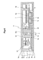
- Fig. 1 shows a state in which respective gears are assembled in a case 2
- Fig. 2(a) shows a state in which a substrate 7 is assembled
- Fig. 2(b) shows a state in which a terminal block 8 is assembled.
- Fig. 3 shows an upper plane of a rotational angle detector.
- a part of a rotor gear 3 is broken in order to show an opening section 2a of the case 2.
- FIG. 4 shows an enlargement of A-A sectional plane in Fig. 1
- Fig. 5 shows an enlargement of B-B sectional plane in Fig. 1.
- the case 2 which accommodates respective gears and the like is provided with a through-hole 2a to allow a steering shaft to penetrate through.
- a through-hole 9a is provided to allow the steering shaft to penetrate through.
- the rotor gear 3 supported by the case 2 and the cover 9 is coaxially arranged with the through-holes 2a, 9a.
- the rotor gear 3 is composed of a cylindrical cylinder section 3c and gear teeth 3b provided on a periphery of the cylinder section 3c, and is provided with two engaging sections 3a which are protruded from an inside plane of the cylinder section 3c and fitted into a concave section of the steering shaft (not shown).
- a gear tooth 3b of the rotor gear 3 is interposed between a cylindrical convex section 2b extending toward the side of the cover 9 from an edge of the through-hole 2a of the case 2 and a cylindrical convex section 9b extending toward the side of the case 2 from an edge of the through-hole 9a of the cover 9, and thus clattering in the axial direction of the rotor gear 3 is suppressed.
- a rotational shaft 4b is pressed into the case 2 and protrudes toward the side of the cover 9.
- a speed increase side detecting gear 4 is fitted into the rotational shaft 4b, and the speed increase side detecting gear 4 is made pivotal about the rotational shaft 4b.
- the speed increase side detecting gear 4 is in mesh with the rotor gear 3 and receives rotation of the rotor gear 3 to rotate in a form to increase the speed.
- a rotational central shaft 54 protrudes from a plane of one side of a speed reduction system 5 provided with a planetary gear system.
- the rotational central shaft 54 protruding from the speed reduction system 5 is inserted into a supporting hole 2c provided on the case 2.
- the speed reduction system 5 is provided with an operating gear 50 in mesh with the rotor gear 3, and after the rotation of the rotor gear 3 is reduced by the planetary gear system provided inside, the rotation is outputted from a driven gear 51.
- the rotational shaft 6b is pressed into the case 2 and protrudes toward the side of the cover 9.
- the speed reduction side detecting gear 6 is fitted into the rotational shaft 6b, and the speed reduction side detecting gear 6 is made pivotal about the rotational shaft 6b.
- a convex section 9e extends from a plane of a side opposing to the speed reduction side detecting gear 6 toward the speed reduction side detecting gear 6.
- Movement of the speed reduction side detecting gear 6 toward the axial direction is regulated by the convex section 9e, and thereby clattering in the axial direction of the speed reduction side detecting gear 6 is suppressed.
- the speed reduction side detecting gear 6 rotates not more than 180 degrees even if the steering is rotated to the maximum rotation speed (lock-to-lock).
- a convex section is provided, although not shown, at a suitable predetermined position in order to suppress clattering of the speed increase side detecting gear 4 and the speed reduction side detecting gear 6 in addition to the convex sections 9c, 9d, and 9e.
- a substrate 7 is arranged so as to cover at least the speed increase side detecting gear 4 and the speed reduction side detecting gear 6, and further to cover left half of the case 2 in Fig. 2(a).
- an MR sensor 7a for detecting a rotational state of the speed increase side detecting gear 4 is assembled. Further, as shown in Fig. 4, an MR sensor 7b is assembled at a position opposing to the magnet 6a of the speed reduction side detecting gear 6 on the substrate 7.
- a circuit (not shown) for performing processing and the like of a signal detected by the MR sensors 7a, 7b is attached at a position not interfering with other members.
- a terminal block 8 is arranged so as to be overlapped on the substrate 7.
- the terminal block 8 is provided with a connector section 8a to be connected with a control device or the like of a vehicle side.
- a connector section 8a protrudes to a side opposite to the side overlapped with the substrate 7.
- the terminal block 8 has a terminal (not shown) which is soldered to a terminal provided on the substrate 7, and further is temporarily fixed by a snap fit to the substrate 7.
- the terminal block 8 receives a detection signal or the like from the substrate 7 and outputs it to the outside from the connector section 8a, or inputs a signal or the like inputted from the connector section 8a to the substrate 7.
- the substrate 7 and the terminal block 8 are provided with through-holes 7c, 7d, 7e, 8b, and 8c at positions corresponding to convex sections 9c, 9d, and 9e, in order to avoid interference with the convex sections 9c, 9d, and 9e for suppressing the clatters of the speed increase side detecting gear 4 and/or the speed reduction side detecting gear 6.
- a rotational angle detector 1 is constituted in the case 2 by covering an opening of the case 2 by the cover 9 in a state where the rotor gear 3, the speed increase side detecting gear 4, the speed reduction system 5, the speed reduction side detecting gear 6, the substrate 7, and the terminal block 8 are assembled, and by fixing the cover 9 to the case 2 by a screw 10 and the snap fit (not shown).
- the substrate 7 and the terminal block 8 are also fixed to the case 2 together with the cover 9.
- the cover 9 is provided with a through-hole 9f to allow the connector 8a, mounted on the terminal block 8, to penetrate through.
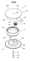
- Fig. 6 is an exploded perspective view of the speed reduction system 5
- Fig. 7 is a view of a stationary gear 53 viewed from the side of an internal gear 53a.
- the speed reduction system 5 comprises an operating gear 50 into which a rotation from the rotor gear 3 is inputted, a driven gear 51 for outputting a reduced rotation, a planetary gear 52, a stationary gear 53, a rotational central shaft 54, and a snap ring 55.
- the operating gear 50 comprises a gear section 50a which is in mesh with the rotor gear 3 to receive a rotation from the rotor 3, a rotational shaft section 50b which cylindrically protrudes from the gear section 50a to work as the rotational shaft of the ring-shaped driven gear 51, a shaft supporting section 50d which cylindrically protrudes in the same direction as the rotational shaft section 50b in an axially central position of the gear section 50a and an inside of which is penetrated through by the rotational central shaft 54, and a rotational shaft section 50c which protrudes from a position deviated from the shaft supporting section 50d inside the rotational shaft section 50b to work as an rotational shaft of the planetary gear 52.
- the driven gear 51 comprises an outer gear section 51 a and an internal gear section 51 b, which are coaxially connected with each other.
- the driven gear 51 is pivotally fitted into outer peripheral side of the rotational shaft 50b which protrudes from the operating gear 50 on the internal peripheral side of the outer gear 51a, and is pivotally supported by the rotational shaft section 50b working as a shaft.
- outer gear section 51 a is in mesh with the speed reduction side detecting gear 6 (refer to Fig. 4).
- the planetary gear 52 comprises a planetary first gear section 52a and a planetary second gear section 52b which are coaxially connected, and the planetary first gear section 52a has a diameter larger than the planetary second gear section 52b (having a larger number of teeth). Because of difference in the number of teeth between the planetary first gear section 52a and the planetary second gear section 52b, freedom in designing is enhanced.
- the planetary gear 52 is pivotally supported by a rotational shaft section 50c, and the planetary first gear section 52a is in mesh with the internal gear section 51 b of the driven gear 51.
- the stationary gear 53 comprises a disk-shaped main body section 53d which is formed in substantially the same size as the gear section 50a of the operating gear 50 and interposes the driven gear 51 together with the gear section 50a, an internal gear section 53a which protrudes toward the side of the driven gear 51 from the main body section 53d (refer to Fig. 7), and arm sections 53b, 53c which protrude outward from the outer peripheral plane of the internal gear section 53a (refer to Fig. 7).
- the internal gear section 53a has an outer shape formed in substantially the same size as the internal gear section 51 b of the driven gear 51, and each of the internal gear sections 51 b, 53a has an end plane in the axial direction which is slidably touched each other.
- the internal gear section 53a is in mesh with the planetary second gear section 52b of the planetary gear 52.
- the arm sections 53b, 53c are respectively provided with a screw hole, and mounted in the case 2 by a screw (not shown) as particularly shown in Fig. 1, and thereby the stationary gear 53 is fixed to the case 2.
- a shaft hole 53e is provided on the main body section 53d, and in a state where the operating gear 50, the driven gear 51, the planetary gear 52, and the stationary gear 53 are assembled, a rotational central shaft 54 is inserted from the side of the operating gear 50 through the shaft supporting section 50d, and the insertion direction tip end side of the rotational central shaft 54 is pressed into the shaft hole 53e.
- the snap ring 55 is fitted into a groove 54a provided on the rotational central shaft 54 such that the operating gear 50 is not pulled out to drop from the rotational central shaft 54 in a state where the rotational central shaft 54 is inserted into the operating gear 50.
- the rotational central shaft 54 protrudes by a predetermined length from the operating gear 50 as particularly shown in Fig. 4.
- the speed reduction system 5 is constituted as described above, and reduces the rotation speed of the rotor gear 3 inputted from the gear section 50a of the operating gear 50, and outputs it from the outer gear section 51a of the driven gear 51.
- a lock-to-lock rotational angle of a steering is set to be 1440° (from +720° to -720°), and the gear ratio of the speed reduction system is set to be 1/8. Accordingly, when the steering is rotated lock-to-lock, the speed reduction side detecting gear 6 rotates by one rotation.
- the gear ratio of the speed increase system is set such that the speed increase side detecting gear 4 makes two rotations for one rotation of the rotor gear 3. Accordingly, by detecting the rotational state of the speed increase side detecting gear 4 by the MR sensor 7a, the rotational state of the rotor gear 3 can be detected by the resolution of twice.
- the rotation of the rotor 3 is transmitted to the operating gear 50 of the speed reduction system 5 to rotate the operating gear 50, and thus the planetary gear 52 revolves about the shaft supporting section 50d which is the rotational shaft of the operating gear 50.
- the planetary gear 52 Since the planetary second gear section 52b is in mesh with the internal gear section 53a of the stationary gear 53 fixed to the case 2, the planetary gear 52 revolves about the shaft supporting section 50d and also rotates on its axis.
- the rotation of the rotor gear 3 is sequentially transmitted to the operating gear 50, the planetary gear 52, the driven gear 51, and the speed reduction side detecting gear 6, and the rotation of the rotor gear 3 is reduced to 1/8 in the process of the transmission, which is transmitted to the speed reduction side detecting gear 6.
- the rotation speed of the rotor gear 3 is increased to twice, which is transmitted to the speed increase side detecting gear 4 of the speed increase system.
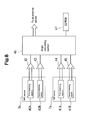
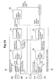
- Fig. 8 shows a functional block diagram for computing the steering angle
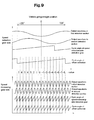
- Fig. 9 shows waveforms outputted from the MR sensor.
- MR sensor 7b is provided with a first detecting section 40A and a second detecting section 40B, and in association with the rotation of the magnet 6a fitted in the speed reduction side detecting gear 6, waveforms (waveforms showing voltage fluctuation) are outputted from respective detecting sections (40A, 40B). These two waveforms are different in phase by 90°.
- the MR sensor 7a is provided with a first detecting section 41A and a second detecting section 41 B, and outputs two waveforms (waveforms showing voltage fluctuation) having different phases by 90° in association with the rotation of the magnet 4a fitted in the speed increase side detecting gear 4.
- Output waveforms from respective detecting sections (40A, 40B, 41A, 41 B) are respectively amplified by amplifiers 42 to 45, which are inputted into an angle calculating section 46.
- waveforms inputted from the MR sensor 7b for detecting the rotational state of the speed reduction system side are shown (the first detecting section output waveform, and the second detecting section output waveform), and in the lower part thereof, the waveforms inputted from the MR sensor 7a for detecting the rotational state of the speed increase system side (the side of the speed increase side detecting gear 4) are shown (the first detecting section output waveform, and the second detecting section output waveform).
- the angle calculating section 46 detects a rotational angle of the steering based on the waveform inputted.
- angle calculating section 46 offsets the waveform inputted, by use of an offset correcting value recorded in an EEPROM 47.
- Fig. 10 is a block diagram showing processing performed in the angle calculating section 46.
- amplifiers 42 to 45 are omitted in Fig. 10.
- the angle calculating section 46 comprises a speed reduction system side computing section 70 for computing an approximate absolute angle of the steering from the rotational angle of the speed reduction system (speed reduction side detecting gear 6), a speed increase system side computing section 60 for computing a detailed absolute angle of the steering from the rotational angle of the speed increase system (speed increase side detecting gear 4), and a failure diagnosis section 80 for performing failure analysis of the MR sensors 7a, 7b by the approximate absolute value and the detailed absolute value.
- the speed reduction system side computing section 70 is provided with a cycle angle calculating section 71, an offset correction section 72, an i-value computing section 73, and a steering angle converting section 74.
- the cycle angle calculating section 71 determines a cycle angle of the speed reduction side detecting gear 6 from two waveforms, which are different in phase by 90°, and outputted from the first detecting section 40A and the second detecting section 40B.
- Fig. 9 shows a relation between the waveforms outputted from the first detecting section 40A and the second detecting section 40B, and the cycle angle of the speed reduction side detecting gear 6.
- cycle angle of the speed reduction side detecting gear 6 makes one cycle when the steering rotates from lock-to-lock (1440°).
- the offset correction section 72 performs correction of the cycle angle computed by the cycle angle calculating section 71 by use of the speed reduction side detecting gear offset value stored in the EEPROM 47.
- the correction is to convert the cycle angle into an angle having a straight running position of a vehicle as the reference by adding the speed reduction side detecting gear offset value to the cycle angle.
- the steering angle converting section 74 converts the offset corrected cycle angle corrected by the offset correction section 72 into the absolute angle of the steering.
- the absolute angle of the steering converted by the steering angle converting section 74 is also referred to as the approximate absolute angle.
- the i-value computing section 73 computes the i-value which corresponds to the offset corrected cycle angle corrected by the offset correction section 72.
- the i-value is, as shown in Fig. 9, obtained by dividing the rotational angle to lock-to-lock of the steering by each of 90° to the left and to the right from the center which is the straight running position of the vehicle, and the rotational angle of the steering is expressed in a unit of 90°. It should be noted that the i-value is a value between -8 to 7.
- the i-value computing section 73 outputs the computed i-value to the side of the speed increase system side computing section 60.
- the speed increase side computing section 60 comprises a cycle angle calculating section 61, an offset correction section 62, and a steering angle converting section 63.
- the cycle angle calculating section 61 determines the cycle angle of the speed increase side detecting gear 4 from the waveforms which are different in phase by 90° and are outputted from the first detecting section 41A and the second detecting section 41 B, in the same way as the cycle angle calculating section 71.
- Fig. 9 shows a relation between the waveforms outputted from the first detecting section 41A and the second detecting section 41 B, and the cycle angle of the speed increase side detecting gear 4.
- cycle angle of the speed increase side detecting gear 4 makes one cycle when the steering rotates 90°.
- the offset correction section 62 performs correction of the cycle angle computed by the cycle angle calculating section 61 by use of the speed increase side detecting gear offset value stored in the EEPROM 47, in the same way as the offset correction section 72.
- both of the speed reduction side detecting gear offset value and the speed increase side detecting gear offset value are previously stored.
- An offset corrected cycle angle is obtained by the correction by the offset correction section 62.
- the steering angle converting section 63 converts the offset corrected cycle angle into the absolute value of the steering by use of the i-value outputted from the speed reduction system side computing section 70.
- the rotation of the speed increase side detecting gear 4 is increased to twice of the rotation of the rotor gear 3 which rotates integrally with the steering shaft, and thus the offset corrected cycle angle is divided by two and, further, a value obtained by multiplying the i-value with 90 is added.
- ⁇ is the absolute angle of the steering
- i is the i-value (-8, -7, ....6, 7)
- ⁇ is the offset corrected cycle angle.
- the speed increase side detecting gear 4 is increased to twice of the speed of the rotor gear 3, the rotational state of the rotor gear 3 can be detected by the resolution of twice by detecting the rotational state of the speed increase side detecting gear 4.
- the steering absolute angle converted by the steering angle converting section 63 is more in detail than the steering absolute angle converted by the steering angle converting section 74.
- the steering absolute angle obtained by conversion by the steering angle converting section 63 is also referred to as a detailed absolute angle.
- the i-value is outputted from the speed reduction system side computing section 70 to the speed increase system side computing section 60, and thereafter, the steering angle converting section 63 per se increases or decreases the i-value in accordance with the fluctuation of the offset corrected cycle angle, and the detailed absolute angle is computed by use of the increased or decreased i-value and the offset corrected cycle angle.
- the detailed absolute angle of the steering thus obtained is outputted toward an outside device such as a vehicle control device (not shown) or the like from the angle calculating section 46.
- the failure diagnosis section 80 compares the approximate absolute angle outputted from the steering angle converting section 74 of the decelerating system side computing section 70 with the detailed absolute angle outputted from the steering angle converting section 63 of the speed increase system side computing section 60, and when the difference of the absolute angle is not less than a certain value, it is determined that a failure is caused in either of the MR sensor 7a or the MR sensor 7b, and a failure diagnosis result is outputted to an outside device not shown.
- the rotor gear 3 constitutes the rotor
- the speed reduction side detecting gear 6 constitutes the speed reduction side detecting rotor
- the speed increase side detecting gear 4 constitutes the speed increase side detecting rotor
- the speed reduction system 5 constitutes the planetary gear system.
- the MR sensor 7b and the cycle angle calculating section 71 constitute the speed reduction side rotation detecting section
- the MR sensor 7a and the cycle angle calculating section 61 constitute the speed increase side rotation detecting section.
- the steering angle converting section 74 constitutes the approximate absolute angle calculating section
- the steering angle converting section 63 constitutes the absolute rotational angle detecting section.
- the present embodiment is constituted as described above, the rotation of the rotor gear 3 which rotates integrally with the steering shaft is reduced by the speed reduction system 5 constituted by the planetary gear system, and the rotation after the speed reduction is made to be transmitted to the speed reduction side detecting gear 6. Therefore, the transmission efficiency of the rotation is improved. Further, since respective shafts of the operating gear 50, the driven gear 51, the planetary gear 52, and the stationary gear 53 are directed to the same direction, the rotation of the steering shaft can be transmitted to the speed reduction side detecting gear 6 with reduced clattering. Accordingly, since the clattering in the speed reduction system 5 is reduced, the rotational angle of the steering shaft can be more accurately detected.
- the speed reduction system 5 for reducing the rotation of the rotor gear 3 is adapted to be constituted by the planetary gear system, the speed reduction system 5 can be formed in compact without spreading in the widening direction of the gear, in comparison with a case where the speed reduction is performed by a wheel row of simple spur gears.
- the speed reduction system 5 is adapted to be assembled as one unit in the case 2, even in a case, for example, where the rotational angle detector 1 is attached on a vehicle having different maximum rotational angle of the steering, it can be applied only by suitably exchanging with the speed reduction system having different speed reduction ratio, and an alteration of mechanical parts inside the rotational angle detector 1 can be minimized.
- Computation of the absolute angle of the steering is made to be performed by use of the i-value computed by the i-value computing section 73 from the detection result of the MR sensor 7b which detects the rotational state of the speed reduction side detecting gear 6, and the detection result of the MR sensor 7a which detects the rotational state of the speed increase side detecting gear 4, and the absolute angle of the steering can be computed in detail as well as in high precision.
- failure diagnosis section 80 is adapted to determine whether any failure is generated in the MR sensors 7a, 7b, by comparing the approximate absolute value of the steering computed by the speed reduction system side computing section 70 with the detailed absolute angle computed by the speed increase system side computing section 60, reliability of the steering rotational angle detection by the rotational angle detector 1 can be improved.
- the failure diagnosis can be performed without an increase in costs or in size.
Landscapes
- Physics & Mathematics (AREA)
- General Physics & Mathematics (AREA)
- Engineering & Computer Science (AREA)
- Chemical & Material Sciences (AREA)
- Combustion & Propulsion (AREA)
- Transportation (AREA)
- Mechanical Engineering (AREA)
- Transmission And Conversion Of Sensor Element Output (AREA)
- Measurement Of Length, Angles, Or The Like Using Electric Or Magnetic Means (AREA)
- Power Steering Mechanism (AREA)
- Length Measuring Devices With Unspecified Measuring Means (AREA)
Applications Claiming Priority (1)
| Application Number | Priority Date | Filing Date | Title |
|---|---|---|---|
| JP2006228581A JP2008051668A (ja) | 2006-08-25 | 2006-08-25 | 回転角度検出装置 |
Publications (1)
| Publication Number | Publication Date |
|---|---|
| EP1892498A1 true EP1892498A1 (de) | 2008-02-27 |
Family
ID=38671028
Family Applications (1)
| Application Number | Title | Priority Date | Filing Date |
|---|---|---|---|
| EP07016407A Withdrawn EP1892498A1 (de) | 2006-08-25 | 2007-08-22 | Rotationswinkelmesser |
Country Status (4)
| Country | Link |
|---|---|
| US (1) | US20080051961A1 (de) |
| EP (1) | EP1892498A1 (de) |
| JP (1) | JP2008051668A (de) |
| KR (1) | KR20080019179A (de) |
Cited By (10)
| Publication number | Priority date | Publication date | Assignee | Title |
|---|---|---|---|---|
| WO2009106227A2 (de) | 2008-02-27 | 2009-09-03 | Valeo Schalter Und Sensoren Gmbh | Anordnung zur erfassung eines drehwinkels |
| EP2446726A1 (de) * | 2010-10-29 | 2012-05-02 | CNH Italia S.p.A. | Lenkradbewegung und automatischer Drehsignalsensorrücksteller |
| EP2330385A3 (de) * | 2009-11-19 | 2014-02-05 | Sanyo Denki Co., Ltd. | Magnetischer Absolutwertgeber |
| EP2873945A4 (de) * | 2012-07-10 | 2016-03-09 | Wanxiang Qianchao Shanghai Automotive Systems Co Ltd | Vorrichtung und verfahren zur erkennung eines absoluten mehrfachdrehungswinkels |
| WO2017045930A1 (de) * | 2015-09-17 | 2017-03-23 | Bourns, Inc. | Lenkwinkelsensor mit funktioneller sicherheit |
| EP3385679A1 (de) * | 2017-04-06 | 2018-10-10 | Melexis Technologies SA | Redundante fehlererkennungsvorrichtung und verfahren |
| CN109804225A (zh) * | 2016-08-18 | 2019-05-24 | 法雷奥开关和传感器有限责任公司 | 用于确定轴的绝对旋转角度的传感器系统、用于确定轴的绝对旋转角度的方法以及具有传感器系统的车辆 |
| CN110044252A (zh) * | 2019-04-02 | 2019-07-23 | 武汉理岩控制技术有限公司 | 一种用于检测轴转动角度的测量装置及测量方法 |
| CN111947549A (zh) * | 2019-05-14 | 2020-11-17 | 株式会社捷太格特 | 旋转角度检测装置 |
| US20210223126A1 (en) * | 2020-01-16 | 2021-07-22 | Jtekt Corporation | Rotation angle detection device |
Families Citing this family (16)
| Publication number | Priority date | Publication date | Assignee | Title |
|---|---|---|---|---|
| WO2008050578A1 (en) * | 2006-10-27 | 2008-05-02 | The Furukawa Electric Co., Ltd. | Rotation angle detection device and rotation angle detection method |
| JP5597914B2 (ja) * | 2008-08-04 | 2014-10-01 | パナソニック株式会社 | 回転角度検出装置 |
| CN102132126B (zh) | 2008-08-26 | 2015-04-08 | 株式会社尼康 | 编码器系统、信号处理方法 |
| KR200470310Y1 (ko) * | 2008-12-15 | 2013-12-06 | 엘지이노텍 주식회사 | 차량용 조향장치의 센서 |
| KR200470312Y1 (ko) * | 2008-12-15 | 2013-12-06 | 엘지이노텍 주식회사 | 차량용 조향장치의 센서 |
| JP5001309B2 (ja) * | 2009-02-02 | 2012-08-15 | 株式会社ショーワ | 検出装置及びパワーステアリング装置 |
| JP5016625B2 (ja) * | 2009-03-11 | 2012-09-05 | 株式会社ショーワ | 検出装置及びパワーステアリング装置 |
| JP5832509B2 (ja) * | 2013-11-28 | 2015-12-16 | ファナック株式会社 | モータと主軸との間の動力伝達部の異常検出機能を有するモータ制御装置 |
| KR102021461B1 (ko) * | 2015-12-18 | 2019-09-16 | 한국원자력연구원 | 모터 제어 장치 및 방법 |
| DE102017004672A1 (de) * | 2017-05-16 | 2018-11-22 | Hengstler Gmbh | Multiturn-Winkelmessgerät |
| WO2020004715A1 (en) * | 2018-06-27 | 2020-01-02 | Alienrobot Inc. | Integrated actuator using magnetic sensor |
| JP7303655B2 (ja) * | 2019-03-29 | 2023-07-05 | ミネベアミツミ株式会社 | アブソリュートエンコーダ |
| CN113137903B (zh) * | 2020-01-19 | 2023-07-07 | 南京泉峰科技有限公司 | 角度尺及角度计算方法 |
| JP7587961B2 (ja) * | 2020-10-22 | 2024-11-21 | ミネベアミツミ株式会社 | 回転検出装置 |
| KR20230004035A (ko) | 2021-06-30 | 2023-01-06 | 삼성전자주식회사 | 냉장고 및 그 제어 방법 |
| WO2025165053A1 (ko) * | 2024-01-31 | 2025-08-07 | 엘지이노텍 주식회사 | 조향각 센서 |
Citations (3)
| Publication number | Priority date | Publication date | Assignee | Title |
|---|---|---|---|---|
| DE9013001U1 (de) * | 1990-09-12 | 1990-11-15 | Wilhelm Ruf KG, 8000 München | Drehwinkelgeber, insbesondere Lenkwinkelgeber für Kraftfahrzeuge |
| EP1018466A2 (de) * | 1999-01-08 | 2000-07-12 | Alps Electric Co., Ltd. | Drehsensor |
| GB2353840A (en) * | 1999-09-06 | 2001-03-07 | Pwb Ruhlatec Ind Prod Gmbh | Reduction gear drive for measuring angles with an optoelectric device |
Family Cites Families (4)
| Publication number | Priority date | Publication date | Assignee | Title |
|---|---|---|---|---|
| JPH09132153A (ja) * | 1995-11-06 | 1997-05-20 | Toyoda Mach Works Ltd | 電気式動力舵取装置 |
| WO2005115819A1 (ja) * | 2004-05-31 | 2005-12-08 | Jtekt Corporation | 車両用操舵装置 |
| EP1693599B1 (de) * | 2005-02-16 | 2011-06-22 | Jtekt Corporation | Fahrzeuglenkvorrichtung |
| JP4592482B2 (ja) * | 2005-04-15 | 2010-12-01 | 株式会社デンソー | 車両搭載装置 |
-
2006
- 2006-08-25 JP JP2006228581A patent/JP2008051668A/ja not_active Withdrawn
-
2007
- 2007-08-20 US US11/892,038 patent/US20080051961A1/en not_active Abandoned
- 2007-08-22 EP EP07016407A patent/EP1892498A1/de not_active Withdrawn
- 2007-08-22 KR KR1020070084525A patent/KR20080019179A/ko not_active Withdrawn
Patent Citations (3)
| Publication number | Priority date | Publication date | Assignee | Title |
|---|---|---|---|---|
| DE9013001U1 (de) * | 1990-09-12 | 1990-11-15 | Wilhelm Ruf KG, 8000 München | Drehwinkelgeber, insbesondere Lenkwinkelgeber für Kraftfahrzeuge |
| EP1018466A2 (de) * | 1999-01-08 | 2000-07-12 | Alps Electric Co., Ltd. | Drehsensor |
| GB2353840A (en) * | 1999-09-06 | 2001-03-07 | Pwb Ruhlatec Ind Prod Gmbh | Reduction gear drive for measuring angles with an optoelectric device |
Cited By (17)
| Publication number | Priority date | Publication date | Assignee | Title |
|---|---|---|---|---|
| WO2009106227A3 (de) * | 2008-02-27 | 2009-12-03 | Valeo Schalter Und Sensoren Gmbh | Anordnung zur erfassung eines drehwinkels |
| US8502528B2 (en) | 2008-02-27 | 2013-08-06 | Valeo Schalter Und Sensoren Gmbh | Arrangement for detecting a rotation angle |
| WO2009106227A2 (de) | 2008-02-27 | 2009-09-03 | Valeo Schalter Und Sensoren Gmbh | Anordnung zur erfassung eines drehwinkels |
| EP2330385A3 (de) * | 2009-11-19 | 2014-02-05 | Sanyo Denki Co., Ltd. | Magnetischer Absolutwertgeber |
| EP2446726A1 (de) * | 2010-10-29 | 2012-05-02 | CNH Italia S.p.A. | Lenkradbewegung und automatischer Drehsignalsensorrücksteller |
| EP2873945A4 (de) * | 2012-07-10 | 2016-03-09 | Wanxiang Qianchao Shanghai Automotive Systems Co Ltd | Vorrichtung und verfahren zur erkennung eines absoluten mehrfachdrehungswinkels |
| WO2017045930A1 (de) * | 2015-09-17 | 2017-03-23 | Bourns, Inc. | Lenkwinkelsensor mit funktioneller sicherheit |
| US11009372B2 (en) | 2015-09-17 | 2021-05-18 | Bourns, Inc. | Steering angle sensor with functional security |
| CN109804225A (zh) * | 2016-08-18 | 2019-05-24 | 法雷奥开关和传感器有限责任公司 | 用于确定轴的绝对旋转角度的传感器系统、用于确定轴的绝对旋转角度的方法以及具有传感器系统的车辆 |
| CN108692743A (zh) * | 2017-04-06 | 2018-10-23 | 迈来芯电子科技有限公司 | 冗余故障检测设备和方法 |
| US10571303B2 (en) | 2017-04-06 | 2020-02-25 | Melexis Technologies Sa | Redundant fault detection device and method |
| EP3385679A1 (de) * | 2017-04-06 | 2018-10-10 | Melexis Technologies SA | Redundante fehlererkennungsvorrichtung und verfahren |
| CN108692743B (zh) * | 2017-04-06 | 2021-07-13 | 迈来芯电子科技有限公司 | 冗余故障检测设备和方法 |
| CN110044252A (zh) * | 2019-04-02 | 2019-07-23 | 武汉理岩控制技术有限公司 | 一种用于检测轴转动角度的测量装置及测量方法 |
| CN111947549A (zh) * | 2019-05-14 | 2020-11-17 | 株式会社捷太格特 | 旋转角度检测装置 |
| US20210223126A1 (en) * | 2020-01-16 | 2021-07-22 | Jtekt Corporation | Rotation angle detection device |
| US11953396B2 (en) * | 2020-01-16 | 2024-04-09 | Jtekt Corporation | Rotation angle detection device |
Also Published As
| Publication number | Publication date |
|---|---|
| JP2008051668A (ja) | 2008-03-06 |
| KR20080019179A (ko) | 2008-03-03 |
| US20080051961A1 (en) | 2008-02-28 |
Similar Documents
| Publication | Publication Date | Title |
|---|---|---|
| EP1892498A1 (de) | Rotationswinkelmesser | |
| EP1459959B2 (de) | Kraftfahrzeuglenkung | |
| EP1503172B1 (de) | Vorrichtung zur Erfassung einer Drehung und Kraftfahrzeug mit einer solchen Vorrichtung | |
| US7290772B2 (en) | Stabilizer control device for vehicle | |
| EP1693599B1 (de) | Fahrzeuglenkvorrichtung | |
| JP3232072B2 (ja) | 電気パワーステアリング装置 | |
| JP5675207B2 (ja) | ステアバイワイヤ式操舵装置の反力トルクアクチュエータ | |
| JP2009061836A (ja) | 舵角可変式ステアリング装置 | |
| EP1382950B1 (de) | Drehmomentsensor | |
| KR102454977B1 (ko) | 액츄에이터 및 이를 포함하는 운동 보조 장치 | |
| EP3181430A2 (de) | Lenkhilfevorrichtung | |
| US7772836B2 (en) | Device for detecting absolute angle of multiple rotation and angle detection method | |
| JP5130184B2 (ja) | 回転検出器付き減速装置 | |
| JP2007245819A (ja) | ステアバイワイヤシステムの入力装置 | |
| JP2004175336A (ja) | 車両用操舵装置 | |
| JP2017090347A (ja) | 絶対角度検出システムおよび絶対角度検出方法 | |
| JP3117756B2 (ja) | 変速装置および高減速比減速装置 | |
| JP2004003537A (ja) | 電動アクチュエータ | |
| JP2006275274A (ja) | 回転伝動装置 | |
| JP4727284B2 (ja) | 多回転絶対角度検出機構および検出方法 | |
| JP4015483B2 (ja) | 伝達比可変操舵装置 | |
| JP3964744B2 (ja) | 伝達比可変操舵装置 | |
| JP2505520B2 (ja) | 偏心遊星差動型減速機の位置検出装置 | |
| JP2008051702A (ja) | トルク検出装置 | |
| CN113007335B (zh) | 一种换挡执行器 |
Legal Events
| Date | Code | Title | Description |
|---|---|---|---|
| PUAI | Public reference made under article 153(3) epc to a published international application that has entered the european phase |
Free format text: ORIGINAL CODE: 0009012 |
|
| AK | Designated contracting states |
Kind code of ref document: A1 Designated state(s): AT BE BG CH CY CZ DE DK EE ES FI FR GB GR HU IE IS IT LI LT LU LV MC MT NL PL PT RO SE SI SK TR |
|
| AX | Request for extension of the european patent |
Extension state: AL BA HR MK YU |
|
| 17P | Request for examination filed |
Effective date: 20080809 |
|
| 17Q | First examination report despatched |
Effective date: 20080909 |
|
| AKX | Designation fees paid |
Designated state(s): DE GB |
|
| STAA | Information on the status of an ep patent application or granted ep patent |
Free format text: STATUS: THE APPLICATION IS DEEMED TO BE WITHDRAWN |
|
| 18D | Application deemed to be withdrawn |
Effective date: 20090120 |