EP1892517A2 - Fluoreszenznanoskopieverfahren - Google Patents
Fluoreszenznanoskopieverfahren Download PDFInfo
- Publication number
- EP1892517A2 EP1892517A2 EP06757947A EP06757947A EP1892517A2 EP 1892517 A2 EP1892517 A2 EP 1892517A2 EP 06757947 A EP06757947 A EP 06757947A EP 06757947 A EP06757947 A EP 06757947A EP 1892517 A2 EP1892517 A2 EP 1892517A2
- Authority
- EP
- European Patent Office
- Prior art keywords
- molecules
- fluorescing
- frames
- images
- fluorescent
- Prior art date
- Legal status (The legal status is an assumption and is not a legal conclusion. Google has not performed a legal analysis and makes no representation as to the accuracy of the status listed.)
- Withdrawn
Links
Images

Classifications
-
- G—PHYSICS
- G01—MEASURING; TESTING
- G01N—INVESTIGATING OR ANALYSING MATERIALS BY DETERMINING THEIR CHEMICAL OR PHYSICAL PROPERTIES
- G01N21/00—Investigating or analysing materials by the use of optical means, i.e. using sub-millimetre waves, infrared, visible or ultraviolet light
- G01N21/62—Systems in which the material investigated is excited whereby it emits light or causes a change in wavelength of the incident light
- G01N21/63—Systems in which the material investigated is excited whereby it emits light or causes a change in wavelength of the incident light optically excited
- G01N21/64—Fluorescence; Phosphorescence
- G01N21/645—Specially adapted constructive features of fluorimeters
- G01N21/6456—Spatial resolved fluorescence measurements; Imaging
- G01N21/6458—Fluorescence microscopy
-
- G—PHYSICS
- G01—MEASURING; TESTING
- G01N—INVESTIGATING OR ANALYSING MATERIALS BY DETERMINING THEIR CHEMICAL OR PHYSICAL PROPERTIES
- G01N21/00—Investigating or analysing materials by the use of optical means, i.e. using sub-millimetre waves, infrared, visible or ultraviolet light
- G01N21/62—Systems in which the material investigated is excited whereby it emits light or causes a change in wavelength of the incident light
- G01N21/63—Systems in which the material investigated is excited whereby it emits light or causes a change in wavelength of the incident light optically excited
- G01N21/64—Fluorescence; Phosphorescence
- G01N21/6428—Measuring fluorescence of fluorescent products of reactions or of fluorochrome labelled reactive substances, e.g. measuring quenching effects, using measuring "optrodes"
-
- G—PHYSICS
- G01—MEASURING; TESTING
- G01N—INVESTIGATING OR ANALYSING MATERIALS BY DETERMINING THEIR CHEMICAL OR PHYSICAL PROPERTIES
- G01N21/00—Investigating or analysing materials by the use of optical means, i.e. using sub-millimetre waves, infrared, visible or ultraviolet light
- G01N21/62—Systems in which the material investigated is excited whereby it emits light or causes a change in wavelength of the incident light
- G01N21/63—Systems in which the material investigated is excited whereby it emits light or causes a change in wavelength of the incident light optically excited
- G01N21/64—Fluorescence; Phosphorescence
- G01N21/6486—Measuring fluorescence of biological material, e.g. DNA, RNA, cells
-
- H—ELECTRICITY
- H04—ELECTRIC COMMUNICATION TECHNIQUE
- H04N—PICTORIAL COMMUNICATION, e.g. TELEVISION
- H04N13/00—Stereoscopic video systems; Multi-view video systems; Details thereof
- H04N13/20—Image signal generators
- H04N13/275—Image signal generators from three-dimensional [3D] object models, e.g. computer-generated stereoscopic image signals
-
- H—ELECTRICITY
- H04—ELECTRIC COMMUNICATION TECHNIQUE
- H04N—PICTORIAL COMMUNICATION, e.g. TELEVISION
- H04N7/00—Television systems
- H04N7/18—Closed-circuit television [CCTV] systems, i.e. systems in which the video signal is not broadcast
-
- Y—GENERAL TAGGING OF NEW TECHNOLOGICAL DEVELOPMENTS; GENERAL TAGGING OF CROSS-SECTIONAL TECHNOLOGIES SPANNING OVER SEVERAL SECTIONS OF THE IPC; TECHNICAL SUBJECTS COVERED BY FORMER USPC CROSS-REFERENCE ART COLLECTIONS [XRACs] AND DIGESTS
- Y10—TECHNICAL SUBJECTS COVERED BY FORMER USPC
- Y10S—TECHNICAL SUBJECTS COVERED BY FORMER USPC CROSS-REFERENCE ART COLLECTIONS [XRACs] AND DIGESTS
- Y10S977/00—Nanotechnology
- Y10S977/84—Manufacture, treatment, or detection of nanostructure
-
- Y—GENERAL TAGGING OF NEW TECHNOLOGICAL DEVELOPMENTS; GENERAL TAGGING OF CROSS-SECTIONAL TECHNOLOGIES SPANNING OVER SEVERAL SECTIONS OF THE IPC; TECHNICAL SUBJECTS COVERED BY FORMER USPC CROSS-REFERENCE ART COLLECTIONS [XRACs] AND DIGESTS
- Y10—TECHNICAL SUBJECTS COVERED BY FORMER USPC
- Y10S—TECHNICAL SUBJECTS COVERED BY FORMER USPC CROSS-REFERENCE ART COLLECTIONS [XRACs] AND DIGESTS
- Y10S977/00—Nanotechnology
- Y10S977/84—Manufacture, treatment, or detection of nanostructure
- Y10S977/849—Manufacture, treatment, or detection of nanostructure with scanning probe
- Y10S977/86—Scanning probe structure
- Y10S977/868—Scanning probe structure with optical means
-
- Y—GENERAL TAGGING OF NEW TECHNOLOGICAL DEVELOPMENTS; GENERAL TAGGING OF CROSS-SECTIONAL TECHNOLOGIES SPANNING OVER SEVERAL SECTIONS OF THE IPC; TECHNICAL SUBJECTS COVERED BY FORMER USPC CROSS-REFERENCE ART COLLECTIONS [XRACs] AND DIGESTS
- Y10—TECHNICAL SUBJECTS COVERED BY FORMER USPC
- Y10S—TECHNICAL SUBJECTS COVERED BY FORMER USPC CROSS-REFERENCE ART COLLECTIONS [XRACs] AND DIGESTS
- Y10S977/00—Nanotechnology
- Y10S977/84—Manufacture, treatment, or detection of nanostructure
- Y10S977/849—Manufacture, treatment, or detection of nanostructure with scanning probe
- Y10S977/86—Scanning probe structure
- Y10S977/868—Scanning probe structure with optical means
- Y10S977/869—Optical microscope
-
- Y—GENERAL TAGGING OF NEW TECHNOLOGICAL DEVELOPMENTS; GENERAL TAGGING OF CROSS-SECTIONAL TECHNOLOGIES SPANNING OVER SEVERAL SECTIONS OF THE IPC; TECHNICAL SUBJECTS COVERED BY FORMER USPC CROSS-REFERENCE ART COLLECTIONS [XRACs] AND DIGESTS
- Y10—TECHNICAL SUBJECTS COVERED BY FORMER USPC
- Y10S—TECHNICAL SUBJECTS COVERED BY FORMER USPC CROSS-REFERENCE ART COLLECTIONS [XRACs] AND DIGESTS
- Y10S977/00—Nanotechnology
- Y10S977/84—Manufacture, treatment, or detection of nanostructure
- Y10S977/88—Manufacture, treatment, or detection of nanostructure with arrangement, process, or apparatus for testing
- Y10S977/881—Microscopy or spectroscopy, e.g. sem, tem
-
- Y—GENERAL TAGGING OF NEW TECHNOLOGICAL DEVELOPMENTS; GENERAL TAGGING OF CROSS-SECTIONAL TECHNOLOGIES SPANNING OVER SEVERAL SECTIONS OF THE IPC; TECHNICAL SUBJECTS COVERED BY FORMER USPC CROSS-REFERENCE ART COLLECTIONS [XRACs] AND DIGESTS
- Y10—TECHNICAL SUBJECTS COVERED BY FORMER USPC
- Y10T—TECHNICAL SUBJECTS COVERED BY FORMER US CLASSIFICATION
- Y10T436/00—Chemistry: analytical and immunological testing
- Y10T436/14—Heterocyclic carbon compound [i.e., O, S, N, Se, Te, as only ring hetero atom]
- Y10T436/142222—Hetero-O [e.g., ascorbic acid, etc.]
- Y10T436/143333—Saccharide [e.g., DNA, etc.]
-
- Y—GENERAL TAGGING OF NEW TECHNOLOGICAL DEVELOPMENTS; GENERAL TAGGING OF CROSS-SECTIONAL TECHNOLOGIES SPANNING OVER SEVERAL SECTIONS OF THE IPC; TECHNICAL SUBJECTS COVERED BY FORMER USPC CROSS-REFERENCE ART COLLECTIONS [XRACs] AND DIGESTS
- Y10—TECHNICAL SUBJECTS COVERED BY FORMER USPC
- Y10T—TECHNICAL SUBJECTS COVERED BY FORMER US CLASSIFICATION
- Y10T436/00—Chemistry: analytical and immunological testing
- Y10T436/25—Chemistry: analytical and immunological testing including sample preparation
Definitions
- This invention presents equipment for scientific research, and lens fluorescence microscopes in particular. Such microscopes are used for obtaining images of glass fluorescent objects. More specifically, this invention is a computerized fluorescent-microscopically method of reconstructing images of objects with resolution up to several nanometers (nm).
- optical microscopes which can create zoomed images of an object with object lenses which can show two spots on an object separately only when the distance between them is more than so called diffraction limit.
- ⁇ - light wavelength for light collected by object lens with aperture A n*sin( ⁇ )
- n - refraction index of substance which surrounds object spots ⁇ - angle between object lens axis and extreme rays which fall into object lens and are detected in detector.
- Powerful arc-lamps, incandescent lamps, laser or sun light can be light sources for the microscope. Fluorescence starts in all dye molecules present in lighted area.
- the area is lighted through the object lens using a light-dividing dichroic mirror.
- a light-dividing dichroic mirror lets exiting light to fall on the object and reflects fluorescent light to detector.
- the second type of lighting occurs by sending laser light from the side. This lights the object all the way down or through object glass at total internal reflection angle. In this case light reaches a depth of only 0.3 of light wavelength from border between glass and object which has refraction index lower than glass.
- Object fluorescent light is collected by object lens. It sends an object image for visual observation and registration by means of photomultiplier, photographic tape or digital video-camera.
- the main disadvantage of all existing lens microscopes is that they have limit of distinguishing two neighboring spots. This limit can be calculated according to formula (1).
- Fluorescence, light-diffusion, and reflected light strength, captured in the object near the hole, is measured by means of a photomultiplier.
- the image of object surface is reconstructed by means of computer, which gathers information about the strength of measured light and data on end of glass fiber coordinates.
- the main disadvantages of this system are: need to use expensive high-precision and fast-acting mechanic units, responsible for moving of glass fiber against object; producing of glass fiber with end hole less than 50 nm in diameter turned to be very expensive, complex and difficult for duplicating; the hole is easily dirtied and is not able to reach object surface after this; only insignificant part of light can leave the fiber through the hole with diameter less than light wavelength; if light is stronger, than glass fiber end this can become hot and will be destroyed; it is impossible to detect fluorescence in the areas of the object which are not accessible by glass fiber; only one spot can be detected at a time, surface scanning speed does not exceed 1 square micron per minute.
- Main disadvantages of this system are: there is no information in the article about opportunity to calculate location of detected spots' centers and to generate image on basis of these spots with resolution higher than diffraction limit (see formula 1); approaches to selective dyeing of object structures are not described in the article; there is no description of solving following problem: after dyeing substances will loose color in process of detecting non fluorescing peptide molecules staying in observation area. This will make solution more thick and will not allow replacing such molecules with new fluorescing ones. This does not allow obtaining larger quantity of frames than 500. These large quantities are needed to receive image with resolution higher than allowed by diffraction limit (see formula 1).
- This invention's task is to work out methods of dyeing objects, preparing objects for research, computer analysis of results.
- This computer analysis will allow receiving object image with resolution higher than 20 nm.
- Fluorescent nanoscope can be based on standard modules, used in fluorescent microscopy.
- the invention comprises various modules: an optical system for visual observation and transmitting of object image to digital video camera.
- Video camera should be able to detect and digitize images of separate fluorescing molecules and nanoparticles with low background noise level.
- Second module of the system is computer for recording and analyzing images.
- Third component is a sample holder, located opposite to objective lens.
- Fourth component is set of changeable suppressing color filters for picking up light of sample fluorescence.
- Nanoscope should be equipped with two light sources installed aside from sample holder. Installation angle should assure lighting of all cutting-depth of a sample or in layer less than 150 nm near the glass. Fluorescent molecules in this layer can absorb energy of light waves, flowing through border when lighted on total internal reflection angle.
- Observation object should be preliminary dyed in a solution with saturating concentration of caged dye which starts fluorescing only when UV light pulse separates blocking fluorescence groups from dye molecules. Superfluous dye should be carefully washed out. It is very hard to assure stability of molecular structures for a long time far from covering glass and prism glass holding the object. This is true for objects observed exactly in fresh flushing solution. That is why best resolution of nanoscope can be received only for those layers of the object which are located on the distance not more than 150 nm from prism glass. This is the depth which light reaches when falling on the boundary surface at a total internal reflection angle. In case of observing dead preserved object it is usually possible to observe the object during many hours. Different structures, located near base glass are almost absolute immovable.
- Gaps on glass edges should be hermetically sealed (for example, with paraffin) to avoid drying of solution.
- 3-D nanoscopy needs total immobility of the object and its parts against objective lens. That is why the object should be treated with drying solutions and placed into polymer non-fluorescent substance (for example, epoxy) after dyeing with caged dye and flushed. Cuts of the object of several microns thickness can be used for 3-D reconstruction of the object with 10-20 nm resolution in all tree directions. Such object contained in solid substance can be lighted as it is done in common fluorescent microscopy. Only improvement is that additional flash-lamp should be used in order to turn several hundred no - fluorescing molecules into fluorescing in each frame.
- polymer non-fluorescent substance for example, epoxy
- UV flash-lamp with ⁇ 360 nm periodically lights the object, dyed with non fluorescing dye, and each time turns several hundred (and even thousand) of non-fluorescing molecules into fluorescing ones by photolysis of special chemical groups blocking fluorescence.
- the laser constantly lights the object and excites fluorescence of newly formed fluorescent molecules with such strength, that each of them will send several tens of thousands light quanta in part of a second. Molecule will loose color after its fluorescence registration on digitized frame with low background noise level. Cycling of fluorescent molecules generation, their exiting, registration and loosing color can be repeated tens of thousands of times. Each time new fluorescence molecules will be generated, detected and will loose color.
- Non-fluorescent molecules will not loose color because they do not absorb laser light.
- Tens of thousands of frames can be detected using this method. Hundreds and even thousands of fluorescing molecules can be detected on each frame. It will allow calculating locations of all tens of millions of fluorescing molecules covering surfaces of all structures, located in field of vision.
- Dyes with different active groups can be used for dyeing structures of different nature in different colors. Active groups can link to either proteins, either nucleic acids, either fats, etc. (Suggested method name - color nanoscopy).
- the second modification of nanoscopy method is based on the fact that Brownian motion of very bright fluorescing and resistant to loosing color nanoparticles is possible inside most part of volume of biological sample with penetrated membranes, filled with salt solution. Nanoparticles are presented by ficobiliprotein molecules or fluorescing micro spheres 10-40 nm in diameter. This motion can be regulated by electrophoresis with current, provided by several pairs of interlacing electrodes. Current directs particles' motion in different directions. So they scan all accessible volume.
- Both suggested methods can assure nanoscope resolution up to several nm, depending not from resolving power (formula 1), but from intrinsic mobility of structures in observed part of the object during long time period.
- Second factor is proportion between noise and signal in video data. Both factors can be adjusted by various modifications of presented methods. For example, some bright shining key fluorescing particles can be introduced into object. Then coordinates of changing particles can be calculated taking into account moving in vision area of key particles rigidly connected with the object. Such approach allows reaching 2-D distinguishing of parts of the object, located on the distance of several nm,
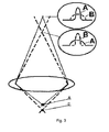
- Diameter and intensity of spots from fluorescing particles which are projected on CCD depends from distance between particle and object lens. Two cameras, focused on different focal planes, show one particle with different diameters and different intensity distribution along diameters. The diagrams in the upper right corner of the figure illustrate differences between diameters and distribution of intensity along diameters depending from cameras and fluorescing particles location.
- nanoscope in some cases can be helpful in finding centers of spots which are created by fluorescing particles in two-three different wavelengths and same exciting status. It can be done by means of separating light dichroic mirrors. Such mirrors pass light with one wavelength to one camera and reflect light with other wavelength to other camera.
- presented invention allows to reconstruct simultaneously with nano resolution location of several different types of object molecules. These molecules will be dyed with dyes having different emitting wavelengths. This will allow enlarged quantities of simultaneously seen and detected separately spots from fluorescing particles. This can be achieved due to the fact that they can be seen separately in waves of different lengths even if corresponding spots of different colors are seen interfering.
- Device operation as a nanoscope can be altered by using fluorescence microscope in the normal regime. This regime gives opportunity of direct visual observation of the object in situ with common resolution (formula 1). It also gives opportunity to detect image with digital video-camera of very high sensitivity and transmit it to computer memory. Then these frames will be analyzed to measure geometric parameters and light intensity in different areas of the frame. This can be used, for example, during bioluminescent and chemoluminescent research.
- the presented drawings show how fluorescent microscope can be modified to implement nanoscopy method according to this invention.
- the fluorescent microscope-nanoscope as it is shown on figures 1 and 2 , is equipped with: one ( figure 1 ) and two ( figure 2 ) monochrome video-cameras (1) with digital output and suppressing color-filters, located opposite to their sensors (CCD). These color-filters pass only fluorescent light to cameras.
- Object (4) is pressed down to glass object holder (5) which has beveled in the form of truncated prism edges.
- Device is also equipped with laser (6) with lens system for exciting fluorescence through prism planes; with pulse UV-source with lens system for photolysis of blocking fluorescence groups, present on dye molecules.
- Eye lens (10) ( figure 1 ) is used for visual observation (9), Unit should be placed into soundproof cabinet, placed on anti-vibration table. Device, providing power to electrophoresis electrodes which direct movement of mobile fluorescing nanoparticles inside the object, filled with salt solution, will be described separately.
- Different methods can be used in order to reach such concentration of simultaneously fluorescing particles. First of all, it is possible to dye object with brightly fluorescing particles in low concentration. This will allow them to move in observation area in Brownian motion and they can be additionally moved with electrophoresis current.
- the object can be dyed with special dyes like 5-carboxyfluorescein-bis-(5- carboxymetoxy-2-nitrobenzil) ester, beta-alanin-carboxylamid, suxynimidil ester (CMNB-caged carboxyfluorescein, SE), fabricated by Molecular Probes, USA.
- CMNB-caged carboxyfluorescein, SE fabricated by Molecular Probes, USA.
- UV flash creates 1000-1600 fluorescing molecules in vision area, laser excites fluorescence in these molecules.
- CCD detects images of fluorescing molecules and particles, overlapped on residual fluorescence.
- Image is digitized in video-camera and is transmitted to computer where previous frame with residue fluorescence is subtracted from it. To received subtracted frame is stored in computer memory for further analysis with the purpose of calculating coordinates of spot center, its averaged diameter, and intensity. Then the object is for some time lighted with laser without detecting its image. It is done to maximize discoloring of already detected molecules. Then whole cycle is repeated.
- Cameras allow to record images of separate fluorescing molecules with frequency of 10 frames per second. Images are recorded with satisfactory proportion of signal and noise. It is possible to detect, for example, 40000 frames during several hours. Each frame will contain up to 1600 images of molecules. If so, total quantity of detected fluorescing molecules' coordinates can reach 64 million, average distance between observed separately molecules can be only 10 nm. This is tens times better than in any other lens microscopes. Frames with molecules' images should be saved without compressing or compressed without loosing quality. This should be done for more exact calculating of molecules' coordinates. Total volume of information on all not compressed frames in one experiment can reach tens of gigabytes. This will not create a problem taking into account modern hard disk drives volume. Literature sources provide information on various algorithms of calculating spots' centers. We have created computer software to perform such calculations and reconstruction of full image based on table of calculated coordinates of spots' centers.
Landscapes
- Health & Medical Sciences (AREA)
- Physics & Mathematics (AREA)
- Immunology (AREA)
- Chemical & Material Sciences (AREA)
- Life Sciences & Earth Sciences (AREA)
- Pathology (AREA)
- Biochemistry (AREA)
- Nuclear Medicine, Radiotherapy & Molecular Imaging (AREA)
- General Physics & Mathematics (AREA)
- General Health & Medical Sciences (AREA)
- Analytical Chemistry (AREA)
- Engineering & Computer Science (AREA)
- Signal Processing (AREA)
- Multimedia (AREA)
- Biomedical Technology (AREA)
- Molecular Biology (AREA)
- Chemical Kinetics & Catalysis (AREA)
- Optics & Photonics (AREA)
- Investigating, Analyzing Materials By Fluorescence Or Luminescence (AREA)
- Microscoopes, Condenser (AREA)
Applications Claiming Priority (2)
| Application Number | Priority Date | Filing Date | Title |
|---|---|---|---|
| RU2005115052/28A RU2305270C2 (ru) | 2005-05-18 | 2005-05-18 | Способ флуоресцентной наноскопии (варианты) |
| PCT/RU2006/000231 WO2006123967A2 (en) | 2005-05-18 | 2006-05-05 | Fluorescent nanoscopy method |
Publications (2)
| Publication Number | Publication Date |
|---|---|
| EP1892517A2 true EP1892517A2 (de) | 2008-02-27 |
| EP1892517A4 EP1892517A4 (de) | 2013-03-13 |
Family
ID=37431689
Family Applications (1)
| Application Number | Title | Priority Date | Filing Date |
|---|---|---|---|
| EP06757947A Withdrawn EP1892517A4 (de) | 2005-05-18 | 2006-05-05 | Fluoreszenznanoskopieverfahren |
Country Status (7)
| Country | Link |
|---|---|
| US (6) | US7803634B2 (de) |
| EP (1) | EP1892517A4 (de) |
| JP (2) | JP5065256B2 (de) |
| CN (2) | CN102023148B (de) |
| CA (1) | CA2648777A1 (de) |
| RU (1) | RU2305270C2 (de) |
| WO (1) | WO2006123967A2 (de) |
Cited By (2)
| Publication number | Priority date | Publication date | Assignee | Title |
|---|---|---|---|---|
| US9360426B2 (en) | 2005-05-23 | 2016-06-07 | Hestzig Llc | Optical microscopy with phototransformable optical labels |
| US10732100B2 (en) | 2018-06-29 | 2020-08-04 | L'oreal | Systems and methods for predicting sun protection factor of sunscreen formulations in vitro |
Families Citing this family (54)
| Publication number | Priority date | Publication date | Assignee | Title |
|---|---|---|---|---|
| RU2305270C2 (ru) | 2005-05-18 | 2007-08-27 | Андрей Алексеевич Климов | Способ флуоресцентной наноскопии (варианты) |
| RU2319948C2 (ru) * | 2006-04-07 | 2008-03-20 | Юрий Владимирович Микляев | Способ получения изображения повышенной разрешающей способности |
| US7838302B2 (en) | 2006-08-07 | 2010-11-23 | President And Fellows Of Harvard College | Sub-diffraction limit image resolution and other imaging techniques |
| US7916304B2 (en) | 2006-12-21 | 2011-03-29 | Howard Hughes Medical Institute | Systems and methods for 3-dimensional interferometric microscopy |
| RU2363948C2 (ru) * | 2007-06-25 | 2009-08-10 | Закрытое акционерное общество "Молекулярно-медицинские технологии" | Многофункциональное устройство для диагностики и способ тестирования биологических объектов |
| WO2009002225A2 (ru) * | 2007-06-25 | 2008-12-31 | Closed Company 'molecular-Medicine Technologies' | Многофункциональное устройство для диагностики и способ тестирования биологических объектов |
| RU2374607C2 (ru) * | 2007-10-11 | 2009-11-27 | Валерий Андреевич Базыленко | Способ контроля шероховатости поверхности на основе эффекта фотолюминесценции частиц наноразмерного уровня |
| WO2009059378A1 (en) * | 2007-11-09 | 2009-05-14 | Commonwealth Scientific & Industrial Research Organisation | Differential aberration correction microscopy (dac) |
| WO2009085218A1 (en) | 2007-12-21 | 2009-07-09 | President And Fellows Of Harvard College | Sub-diffraction limit image resolution in three dimensions |
| US10568535B2 (en) | 2008-05-22 | 2020-02-25 | The Trustees Of Dartmouth College | Surgical navigation with stereovision and associated methods |
| US9170199B2 (en) | 2008-07-24 | 2015-10-27 | Massachusetts Institute Of Technology | Enhanced sensors in three dimensional scanning system |
| US9140649B2 (en) | 2008-07-24 | 2015-09-22 | Massachusetts Institute Of Technology | Inflatable membrane having non-uniform inflation characteristic |
| US9170200B2 (en) | 2008-07-24 | 2015-10-27 | Massachusetts Institute Of Technology | Inflatable membrane with hazard mitigation |
| US8845526B2 (en) | 2008-07-24 | 2014-09-30 | Massachusetts Institute Of Technology | Integrated otoscope and three dimensional scanning system |
| US9291565B2 (en) | 2008-07-24 | 2016-03-22 | Massachusetts Institute Of Technology | Three dimensional scanning using membrane with optical features |
| ES2649488T3 (es) | 2008-07-24 | 2018-01-12 | Massachusetts Institute Of Technology | Sistemas y métodos para la obtención de imágenes usando absorción |
| US8948851B2 (en) | 2009-01-20 | 2015-02-03 | The Trustees Of Dartmouth College | Method and apparatus for depth-resolved fluorescence, chromophore, and oximetry imaging for lesion identification during surgery |
| US8445867B2 (en) * | 2010-02-23 | 2013-05-21 | Board Of Trustees Of The University Of Illinois | Photobleaching and intermittency localization microscopy |
| EP2668487B1 (de) | 2011-01-24 | 2024-11-06 | Roche Molecular Systems, Inc. | Vorrichtungen, systeme und verfahren zur extraktion eines materials aus einer materialprobe |
| JP2013114042A (ja) * | 2011-11-29 | 2013-06-10 | Sony Corp | 画像取得装置、画像取得方法及び画像取得プログラム |
| US8568991B2 (en) | 2011-12-23 | 2013-10-29 | General Electric Company | Photoactivated chemical bleaching of dyes |
| US9176032B2 (en) | 2011-12-23 | 2015-11-03 | General Electric Company | Methods of analyzing an H and E stained biological sample |
| US11510600B2 (en) | 2012-01-04 | 2022-11-29 | The Trustees Of Dartmouth College | Method and apparatus for quantitative and depth resolved hyperspectral fluorescence and reflectance imaging for surgical guidance |
| US11813100B2 (en) | 2012-01-04 | 2023-11-14 | The Trustees Of Dartmouth College | Methods for quantitative and enhanced-contrast molecular medical imaging using cross-modality correction for differing tracer kinetics |
| US12061328B2 (en) | 2012-01-20 | 2024-08-13 | The Trustees Of Dartmouth College | Method and apparatus for quantitative hyperspectral fluorescence and reflectance imaging for surgical guidance |
| US9336592B2 (en) | 2012-02-03 | 2016-05-10 | The Trustees Of Dartmouth College | Method and apparatus for determining tumor shift during surgery using a stereo-optical three-dimensional surface-mapping system |
| CN103536291B (zh) * | 2012-07-10 | 2017-04-19 | 花王株式会社 | 体表皮脂分布的测定方法 |
| RU2502983C1 (ru) * | 2012-08-17 | 2013-12-27 | Игорь Викторович Чеботарь | Способ наноскопии |
| US10743768B2 (en) * | 2012-10-15 | 2020-08-18 | Visen Medical, Inc. | Systems, methods, and apparatus for imaging of diffuse media featuring cross-modality weighting of fluorescent and bioluminescent sources |
| US11937951B2 (en) | 2013-02-13 | 2024-03-26 | The Trustees Of Dartmouth College | Method and apparatus for medical imaging using differencing of multiple fluorophores |
| US11564639B2 (en) | 2013-02-13 | 2023-01-31 | The Trustees Of Dartmouth College | Method and apparatus for medical imaging using differencing of multiple fluorophores |
| JP6037889B2 (ja) * | 2013-02-25 | 2016-12-07 | オリンパス株式会社 | 走査型観察装置 |
| JP2016513794A (ja) | 2013-03-06 | 2016-05-16 | ゼネラル・エレクトリック・カンパニイ | H&e染色された生体試料を分析する方法 |
| JP2015025759A (ja) * | 2013-07-26 | 2015-02-05 | Hoya株式会社 | 基板検査方法、基板製造方法および基板検査装置 |
| CN103411936B (zh) * | 2013-07-29 | 2015-12-02 | 深圳大学 | 一种三维纳米分辨定位方法及装置 |
| RU2544047C1 (ru) * | 2013-10-07 | 2015-03-10 | Федеральное государственное бюджетное образовательное учреждение высшего профессионального образования "Российский химико-технологический университет имени Д.И. Менделеева", РХТУ им. Д.И. Менделеева | Способ определения микровключений примесей в порошковых органических люминофорах |
| JP2018511036A (ja) | 2015-01-31 | 2018-04-19 | エフ.ホフマン−ラ ロシュ アーゲーF. Hoffmann−La Roche Aktiengesellschaft | メソダイセクションのためのシステムおよび方法 |
| JP6836994B2 (ja) * | 2015-01-31 | 2021-03-03 | エフ.ホフマン−ラ ロシュ アーゲーF. Hoffmann−La Roche Aktiengesellschaft | メソダイセクションのためのシステム及び方法 |
| CN104749758A (zh) * | 2015-04-24 | 2015-07-01 | 南开大学 | 折射率荧光显微镜 |
| US10783697B2 (en) | 2016-02-26 | 2020-09-22 | Yale University | Systems, methods, and computer-readable media for ultra-high resolution 3D imaging of whole cells |
| US20180143123A1 (en) * | 2016-09-22 | 2018-05-24 | Mehmet Selim Hanay | System and method for sizing and imaging analytes in microfluidics by multimode electromagnetic resonators |
| US10876933B2 (en) | 2016-11-09 | 2020-12-29 | Ventana Medical Systems, Inc. | Automated tissue dissection instrument and methods of using the same |
| CN107132181A (zh) * | 2017-04-17 | 2017-09-05 | 金华职业技术学院 | 一种研究单分子层的摩擦学的方法 |
| CN107356571A (zh) * | 2017-06-27 | 2017-11-17 | 暨南大学 | 一种测定表面电荷的方法 |
| US10585270B2 (en) * | 2017-10-25 | 2020-03-10 | University Of Vermont And State Agricultural College | Reflected image macroscopy system |
| CN111406274B (zh) * | 2017-12-01 | 2024-04-19 | 索尼公司 | 图像着色设备、图像着色方法、图像学习设备、图像学习方法、程序及图像着色系统 |
| RU2680664C1 (ru) * | 2017-12-18 | 2019-02-25 | Федеральное Государственное Бюджетное Образовательное Учреждение Высшего Образования "Казанский Национальный Исследовательский Технический Университет Им. А.Н. Туполева-Каи", Книту-Каи | Способ регистрации быстрых флуоресцентных сигналов при помощи лазерного сканирующего конфокального микроскопа |
| EP3735606B1 (de) * | 2018-01-02 | 2023-03-22 | King's College London | Verfahren und system für lokalisationsmikroskopie |
| WO2019190549A1 (en) | 2018-03-30 | 2019-10-03 | Perkinelmer Health Sciences, Inc. | Systems and methods for 3d reconstruction of anatomical organs and inclusions using short-wave infrared (swir) projection tomography |
| WO2020030954A1 (en) | 2018-08-09 | 2020-02-13 | Integrative Medicine Clinic, Sia | Theranostics-like protein sanps conjugated to integrin and pmsa targeting peptides and therapy of prostate cancer |
| US10481379B1 (en) | 2018-10-19 | 2019-11-19 | Nanotronics Imaging, Inc. | Method and system for automatically mapping fluid objects on a substrate |
| US20250270662A1 (en) * | 2021-05-20 | 2025-08-28 | Jason P. Gleghorn | Method for enumeration and physical characterization of nanoparticles |
| GB2624509A (en) * | 2022-09-14 | 2024-05-22 | Frank Gunter Wood Michael | System and method of multiple fluorophore visualization |
| CN116879250A (zh) * | 2023-07-07 | 2023-10-13 | 宁波力显智能科技有限公司 | 荧光显微成像方法、装置、计算机设备和存储介质 |
Family Cites Families (35)
| Publication number | Priority date | Publication date | Assignee | Title |
|---|---|---|---|---|
| SU1493673A1 (ru) * | 1987-05-21 | 1989-07-15 | Предприятие П/Я А-1631 | Краситель дл флуоресцентной микроскопии бактериальных клеток, осажденных на мембранном фильтре |
| US5233197A (en) * | 1991-07-15 | 1993-08-03 | University Of Massachusetts Medical Center | High speed digital imaging microscope |
| CN2238435Y (zh) * | 1994-07-12 | 1996-10-23 | 王仲明 | 光荧光显微镜 |
| US6259104B1 (en) * | 1994-07-15 | 2001-07-10 | Stephen C. Baer | Superresolution in optical microscopy and microlithography |
| US5635608A (en) * | 1994-11-08 | 1997-06-03 | Molecular Probes, Inc. | α-carboxy caged compounds |
| DE4445214C2 (de) * | 1994-12-17 | 2000-06-29 | Laser & Med Tech Gmbh | Verfahren zur Bestimmung und Rekonstruktion räumlicher Verteilungen und Intensitäten von Fluoreszenzfarbstoffen und Vorrichtung zur Durchführung des Verfahrens |
| JP3872856B2 (ja) * | 1997-01-23 | 2007-01-24 | オリンパス株式会社 | 蛍光顕微鏡 |
| US6480285B1 (en) * | 1997-01-28 | 2002-11-12 | Zetetic Institute | Multiple layer confocal interference microscopy using wavenumber domain reflectometry and background amplitude reduction and compensation |
| JPH10285613A (ja) * | 1997-03-31 | 1998-10-23 | Shinichi Hirabayashi | 3d画像撮像装置 |
| US7342717B1 (en) * | 1997-07-10 | 2008-03-11 | Ruprecht Karts Universitaet Heidelberg | Wave field microscope with detection point spread function |
| IL127359A0 (en) * | 1998-12-01 | 1999-10-28 | Yeda Res & Dev | Computerized adaptive imaging |
| JP4488259B2 (ja) * | 1999-09-13 | 2010-06-23 | オリンパス株式会社 | 量子ドット観察装置 |
| RU2166201C1 (ru) * | 1999-12-28 | 2001-04-27 | Институт молекулярной биологии им. В.А. Энгельгардта РАН | Флуоресцентный микроскоп |
| JP2001194303A (ja) * | 2000-01-13 | 2001-07-19 | Bunshi Biophotonics Kenkyusho:Kk | 蛍光分子拡散運動解析装置 |
| CN1261159A (zh) * | 2000-03-08 | 2000-07-26 | 中国科学院广州地球化学研究所 | 激光诱导荧光显微镜组装方法 |
| US7110118B2 (en) * | 2000-12-19 | 2006-09-19 | Trustees Of Boston University | Spectral imaging for vertical sectioning |
| JP3958987B2 (ja) * | 2002-03-25 | 2007-08-15 | 浜松ホトニクス株式会社 | フォトンカウンティングシステム及びフォトンカウンティング方法 |
| GB0211072D0 (en) * | 2002-05-15 | 2002-06-26 | Amersham Biosciences Uk Ltd | Reagent and method for the determination of changes in a cellular morphological parameter |
| CN1188529C (zh) * | 2002-06-11 | 2005-02-09 | 刘全俊 | 一种基因芯片的纳米金标记银染检测法 |
| US6953927B2 (en) * | 2002-08-09 | 2005-10-11 | California Institute Of Technology | Method and system for scanning apertureless fluorescence microscope |
| JP2004177312A (ja) * | 2002-11-28 | 2004-06-24 | Japan Science & Technology Agency | 流体の三次元温度・速度同時計測方法 |
| CN1193220C (zh) * | 2002-12-26 | 2005-03-16 | 北京大学 | 生物体组织染色方法 |
| US20040227694A1 (en) * | 2003-05-14 | 2004-11-18 | Xiao-Dong Sun | System and method for a three-dimensional color image display utilizing laser induced fluorescence of nanopartcles and organometallic molecules in a transparent medium |
| JP2004347454A (ja) * | 2003-05-22 | 2004-12-09 | Mitsubishi Rayon Co Ltd | シェーディング補正方法 |
| CN1206534C (zh) * | 2003-07-18 | 2005-06-15 | 北京航天瑞祺科技发展有限公司 | 一种神经网识别荧光染色精子的方法 |
| US7426026B2 (en) * | 2003-10-10 | 2008-09-16 | Hamamatsu Photonics K.K. | Method and system for measuring the concentrations of fluorescent dyes |
| EP1582858A1 (de) * | 2004-03-29 | 2005-10-05 | Max-Planck-Gesellschaft zur Förderung der Wissenschaften e.V. | Verfahren zur Anregung der Moleküle von einem ersten Zustand in einen zweiten Zustand mit einem optischen Signal |
| US7785505B2 (en) * | 2004-04-26 | 2010-08-31 | Drexel University | Methods for use of fluorescent nanoparticles to determine free volume and to detect and deliver materials to repair cracks in polymers and polymer composites |
| WO2006078857A2 (en) * | 2005-01-16 | 2006-07-27 | Baer Stephen C | Single wavelength stimulated emission depletion microscopy |
| US7476787B2 (en) * | 2005-02-23 | 2009-01-13 | Stc.Unm | Addressable field enhancement microscopy |
| DE102005012739B4 (de) * | 2005-03-19 | 2010-09-16 | MAX-PLANCK-Gesellschaft zur Förderung der Wissenschaften e.V. | Verfahren zur Herstellung räumlicher Feinstrukturen |
| DE102005013969A1 (de) * | 2005-03-26 | 2006-10-05 | MAX-PLANCK-Gesellschaft zur Förderung der Wissenschaften e.V. | Verfahren zur mikroskopischen Untersuchung einer räumlichen Feinstruktur |
| US7767414B1 (en) * | 2005-04-20 | 2010-08-03 | The Board Of Trustees Of The Leland Stanford Junior University | Optical imaging of molecular characteristics of biological specimen |
| RU2305270C2 (ru) | 2005-05-18 | 2007-08-27 | Андрей Алексеевич Климов | Способ флуоресцентной наноскопии (варианты) |
| JP4709278B2 (ja) * | 2005-05-23 | 2011-06-22 | エフ. ヘスス ハラルド | 光変換可能な光学標識を用いる光学顕微鏡法 |
-
2005
- 2005-05-18 RU RU2005115052/28A patent/RU2305270C2/ru not_active IP Right Cessation
-
2006
- 2006-05-05 CN CN2010105083360A patent/CN102023148B/zh not_active Expired - Fee Related
- 2006-05-05 EP EP06757947A patent/EP1892517A4/de not_active Withdrawn
- 2006-05-05 JP JP2008512241A patent/JP5065256B2/ja not_active Expired - Fee Related
- 2006-05-05 CN CN2006800264573A patent/CN101228428B/zh not_active Expired - Fee Related
- 2006-05-05 WO PCT/RU2006/000231 patent/WO2006123967A2/ru not_active Ceased
- 2006-05-05 CA CA002648777A patent/CA2648777A1/en not_active Abandoned
- 2006-05-05 US US11/920,661 patent/US7803634B2/en active Active
-
2010
- 2010-09-27 US US12/891,420 patent/US8110405B2/en not_active Expired - Fee Related
-
2012
- 2012-02-06 US US13/366,813 patent/US8334143B2/en not_active Expired - Fee Related
- 2012-06-01 JP JP2012126031A patent/JP5656920B2/ja not_active Expired - Fee Related
- 2012-12-14 US US13/714,609 patent/US8668872B2/en not_active Expired - Lifetime
-
2014
- 2014-01-15 US US14/155,979 patent/US9028757B2/en not_active Expired - Fee Related
-
2015
- 2015-05-12 US US14/710,214 patent/US20150316478A1/en not_active Abandoned
Cited By (8)
| Publication number | Priority date | Publication date | Assignee | Title |
|---|---|---|---|---|
| US9360426B2 (en) | 2005-05-23 | 2016-06-07 | Hestzig Llc | Optical microscopy with phototransformable optical labels |
| EP1894010B2 (de) † | 2005-05-23 | 2016-06-15 | Harald F. Hess | Optische mikroskopie mit phototransformierbaren optischen markern |
| EP2453237B1 (de) * | 2005-05-23 | 2016-12-21 | Harald F. Hess | Optische Mikroskopie mit phototransformierbaren optischen Markern |
| EP2453239B1 (de) * | 2005-05-23 | 2017-04-26 | Harald F. Hess | Optische Mikroskopie mit transformierbaren optischen Markern |
| US10107753B2 (en) | 2005-05-23 | 2018-10-23 | Hestzig Llc | Optical microscopy with phototransformable optical labels |
| US11009460B2 (en) | 2005-05-23 | 2021-05-18 | Hestzig Llc | Optical microscopy with phototransformable optical labels |
| US11988604B2 (en) | 2005-05-23 | 2024-05-21 | Hestzig Llc | Optical microscopy with phototransformable optical labels |
| US10732100B2 (en) | 2018-06-29 | 2020-08-04 | L'oreal | Systems and methods for predicting sun protection factor of sunscreen formulations in vitro |
Also Published As
| Publication number | Publication date |
|---|---|
| US20090045353A1 (en) | 2009-02-19 |
| CN102023148B (zh) | 2013-07-24 |
| US8668872B2 (en) | 2014-03-11 |
| JP5065256B2 (ja) | 2012-10-31 |
| JP5656920B2 (ja) | 2015-01-21 |
| US20130099136A1 (en) | 2013-04-25 |
| US20150316478A1 (en) | 2015-11-05 |
| RU2305270C2 (ru) | 2007-08-27 |
| US20140127079A1 (en) | 2014-05-08 |
| CN101228428B (zh) | 2012-11-07 |
| RU2005115052A (ru) | 2006-11-27 |
| US20120133740A1 (en) | 2012-05-31 |
| US7803634B2 (en) | 2010-09-28 |
| CN101228428A (zh) | 2008-07-23 |
| EP1892517A4 (de) | 2013-03-13 |
| CA2648777A1 (en) | 2006-11-23 |
| WO2006123967A3 (en) | 2007-03-22 |
| US20110175982A1 (en) | 2011-07-21 |
| CN102023148A (zh) | 2011-04-20 |
| JP2008541128A (ja) | 2008-11-20 |
| JP2012198234A (ja) | 2012-10-18 |
| WO2006123967A2 (en) | 2006-11-23 |
| US9028757B2 (en) | 2015-05-12 |
| US8110405B2 (en) | 2012-02-07 |
| US8334143B2 (en) | 2012-12-18 |
Similar Documents
| Publication | Publication Date | Title |
|---|---|---|
| US7803634B2 (en) | Fluorescent nanoscopy method | |
| AU2010200554B2 (en) | Microscope with a viewing direction perpendicular to the illumination direction | |
| US20020030811A1 (en) | Arrangement for visualizing molecules | |
| JP5746161B2 (ja) | 顕微鏡画像における蛍光の評価方法 | |
| US7498551B2 (en) | Apparatus and method for tracking a molecule or particle in three dimensions | |
| JP2022000648A (ja) | ハイスループット生化学的スクリーニング | |
| CN108700520B (zh) | 用于高吞吐量成像的方法和设备 | |
| JP2004361087A (ja) | 生体分子解析装置 | |
| Liu et al. | Spectroscopic fluorescent tracking of a single molecule in a live cell with a dual-objective fluorescent reflection microscope | |
| Garsha | Quantitative fluorescence microscopy: Considerations and controls | |
| Aguet et al. | Microscopy: Basic Principles, Challenges, and Opportunities | |
| HK40002627B (en) | Method and apparatus for high throughput imaging | |
| HK40002627A (en) | Method and apparatus for high throughput imaging |
Legal Events
| Date | Code | Title | Description |
|---|---|---|---|
| PUAI | Public reference made under article 153(3) epc to a published international application that has entered the european phase |
Free format text: ORIGINAL CODE: 0009012 |
|
| 17P | Request for examination filed |
Effective date: 20071218 |
|
| AK | Designated contracting states |
Kind code of ref document: A2 Designated state(s): AT BE BG CH CY CZ DE DK EE ES FI FR GB GR HU IE IS IT LI LT LU LV MC NL PL PT RO SE SI SK TR |
|
| DAX | Request for extension of the european patent (deleted) | ||
| A4 | Supplementary search report drawn up and despatched |
Effective date: 20130207 |
|
| RIC1 | Information provided on ipc code assigned before grant |
Ipc: G01N 21/64 20060101ALI20130201BHEP Ipc: G01N 21/00 20060101AFI20130201BHEP |
|
| STAA | Information on the status of an ep patent application or granted ep patent |
Free format text: STATUS: THE APPLICATION IS DEEMED TO BE WITHDRAWN |
|
| 18D | Application deemed to be withdrawn |
Effective date: 20191203 |