EP1892596A2 - Système et procédé destinés à l'organisation de pièces à usiner à traiter - Google Patents
Système et procédé destinés à l'organisation de pièces à usiner à traiter Download PDFInfo
- Publication number
- EP1892596A2 EP1892596A2 EP07015673A EP07015673A EP1892596A2 EP 1892596 A2 EP1892596 A2 EP 1892596A2 EP 07015673 A EP07015673 A EP 07015673A EP 07015673 A EP07015673 A EP 07015673A EP 1892596 A2 EP1892596 A2 EP 1892596A2
- Authority
- EP
- European Patent Office
- Prior art keywords
- workpiece
- status
- location
- space
- locations
- Prior art date
- Legal status (The legal status is an assumption and is not a legal conclusion. Google has not performed a legal analysis and makes no representation as to the accuracy of the status listed.)
- Withdrawn
Links
Images


Classifications
-
- G—PHYSICS
- G05—CONTROLLING; REGULATING
- G05B—CONTROL OR REGULATING SYSTEMS IN GENERAL; FUNCTIONAL ELEMENTS OF SUCH SYSTEMS; MONITORING OR TESTING ARRANGEMENTS FOR SUCH SYSTEMS OR ELEMENTS
- G05B19/00—Program-control systems
- G05B19/02—Program-control systems electric
- G05B19/418—Total factory control, i.e. centrally controlling a plurality of machines, e.g. direct or distributed numerical control [DNC], flexible manufacturing systems [FMS], integrated manufacturing systems [IMS] or computer integrated manufacturing [CIM]
- G05B19/4183—Total factory control, i.e. centrally controlling a plurality of machines, e.g. direct or distributed numerical control [DNC], flexible manufacturing systems [FMS], integrated manufacturing systems [IMS] or computer integrated manufacturing [CIM] characterised by data acquisition, e.g. workpiece identification
-
- G—PHYSICS
- G05—CONTROLLING; REGULATING
- G05B—CONTROL OR REGULATING SYSTEMS IN GENERAL; FUNCTIONAL ELEMENTS OF SUCH SYSTEMS; MONITORING OR TESTING ARRANGEMENTS FOR SUCH SYSTEMS OR ELEMENTS
- G05B2219/00—Program-control systems
- G05B2219/30—Nc systems
- G05B2219/31—From computer integrated manufacturing till monitoring
- G05B2219/31095—Read write intelligent chip on workpiece, pallet, tool for data exchange
-
- G—PHYSICS
- G05—CONTROLLING; REGULATING
- G05B—CONTROL OR REGULATING SYSTEMS IN GENERAL; FUNCTIONAL ELEMENTS OF SUCH SYSTEMS; MONITORING OR TESTING ARRANGEMENTS FOR SUCH SYSTEMS OR ELEMENTS
- G05B2219/00—Program-control systems
- G05B2219/30—Nc systems
- G05B2219/31—From computer integrated manufacturing till monitoring
- G05B2219/31286—Detect position of articles and equipment by receivers, identify objects by code
-
- G—PHYSICS
- G05—CONTROLLING; REGULATING
- G05B—CONTROL OR REGULATING SYSTEMS IN GENERAL; FUNCTIONAL ELEMENTS OF SUCH SYSTEMS; MONITORING OR TESTING ARRANGEMENTS FOR SUCH SYSTEMS OR ELEMENTS
- G05B2219/00—Program-control systems
- G05B2219/30—Nc systems
- G05B2219/31—From computer integrated manufacturing till monitoring
- G05B2219/31304—Identification of workpiece and data for control, inspection, safety, calibration
-
- G—PHYSICS
- G05—CONTROLLING; REGULATING
- G05B—CONTROL OR REGULATING SYSTEMS IN GENERAL; FUNCTIONAL ELEMENTS OF SUCH SYSTEMS; MONITORING OR TESTING ARRANGEMENTS FOR SUCH SYSTEMS OR ELEMENTS
- G05B2219/00—Program-control systems
- G05B2219/30—Nc systems
- G05B2219/31—From computer integrated manufacturing till monitoring
- G05B2219/31313—Measure weight, dimension and contents of box, tray
-
- G—PHYSICS
- G05—CONTROLLING; REGULATING
- G05B—CONTROL OR REGULATING SYSTEMS IN GENERAL; FUNCTIONAL ELEMENTS OF SUCH SYSTEMS; MONITORING OR TESTING ARRANGEMENTS FOR SUCH SYSTEMS OR ELEMENTS
- G05B2219/00—Program-control systems
- G05B2219/30—Nc systems
- G05B2219/37—Measurements
- G05B2219/37002—Absence, detect absence, presence or correct position of workpiece
-
- Y—GENERAL TAGGING OF NEW TECHNOLOGICAL DEVELOPMENTS; GENERAL TAGGING OF CROSS-SECTIONAL TECHNOLOGIES SPANNING OVER SEVERAL SECTIONS OF THE IPC; TECHNICAL SUBJECTS COVERED BY FORMER USPC CROSS-REFERENCE ART COLLECTIONS [XRACs] AND DIGESTS
- Y02—TECHNOLOGIES OR APPLICATIONS FOR MITIGATION OR ADAPTATION AGAINST CLIMATE CHANGE
- Y02P—CLIMATE CHANGE MITIGATION TECHNOLOGIES IN THE PRODUCTION OR PROCESSING OF GOODS
- Y02P90/00—Enabling technologies with a potential contribution to greenhouse gas [GHG] emissions mitigation
- Y02P90/02—Total factory control, e.g. smart factories, flexible manufacturing systems [FMS] or integrated manufacturing systems [IMS]
Definitions
- the present invention relates to a system for the computer-aided organization of workpieces to be machined and to a corresponding organization method.
- Workpieces are subjected in a production process to a variety of machining operations performed by a variety of different tools.
- the relevant workpiece is drilled, milled, wire EDM and ground, polished and the like.
- the workpiece in question is usually located on a workpiece carrier, in particular on a so-called "pallet", which serves as the basis for clamping the workpiece in the processing devices.
- the productivity pressure means that the throughput times of workpieces must always be shortened and the utilization of the machines must be improved.
- errors in the production process eg. B.
- This known system comprises a plurality of so-called subcells, in each of which a plurality of workpieces are kept and processed, as well as a superordinate master cell with a central control unit and a central robot for feeding the workpieces stored in the master cell to the individual subcells.
- Each individual pallet is provided with an ID, for example in the form of a computer chip, a bar code or an optical code.
- the IDs ensure that the master robot can identify the workpieces in question based on the ID of the pallet and thus connect the correct workpiece, for example an injection mold or an electrode, to the correct carrier provided.
- removal robots have a reading unit on the gripper arm.
- the object of the present invention is to provide a generic system and method for the computer-aided organization of workpieces to be machined in a machining process, in which an automated handling of workpieces with increased process reliability can be performed while the throughput times of workpieces in complex machining processes can be shortened considerably.
- each workpiece space has means for status determination of the relevant workpiece space, a control unit for controlling the individual workpiece locations is provided and a data processing unit, preferably a central data processing unit is provided which communicates with the control unit and in the information requested by the individual workpiece locations is processed and status data is generated.
- a control unit for controlling the individual workpiece locations is provided and a data processing unit, preferably a central data processing unit is provided which communicates with the control unit and in the information requested by the individual workpiece locations is processed and status data is generated.
- a data processing unit preferably a central data processing unit is provided which communicates with the control unit and in the information requested by the individual workpiece locations is processed and status data is generated.
- the status determination of the workpiece location expediently relates to determining whether a workpiece is located at the workpiece location or not. It is thus not necessary for a picking robot to perform an identification every time. This ensures a much faster production process.
- the status determination of the workpiece location also or alternatively relates to the determination of whether a workpiece may be removed from the workpiece location or not and / or introduced or not.
- the aforementioned status determination means that time-consuming erroneous picking or incorrect allocations of tool places are excluded.
- each workpiece space may have a locking device which locks the workpiece on the workpiece location as a function of the determined status of the relevant workpiece location, so that it can not be accidentally removed.
- the status determination of the workpiece location also or alternatively relates to information about the properties of the workpiece, in particular about dimensions of the workpiece and / or alignment data of the workpiece to the pallet.
- This information is expediently obtained via an optical measuring device.
- the device for determining this additional information can be located on the magazine, so that each individual magazine location or the workpiece located therein can be optically read out. Theoretically, however, it is possible also a reading z. B. read the dimensions of the workpiece or its positioning on the pallet at another location and supply the relevant data to the data processing unit.
- a receiving part preferably provided on the respective workpiece space, by means of which the status data can be generated or which serves as the basis for the generation of the status data.
- the receiving part is a reading antenna for identifying a transponder, e.g. an RFID transponder chip of 125 kHz technology, which is located on the pallet or on the workpiece.
- the reading antenna makes it possible to obtain the ID of the work piece located on the work piece including further data relevant to the manufacturing process, such as data. an object reference or the like, read and supply via the control unit of the data processing unit. Due to the use of a reading antenna to identify a transponder, it is possible to retrofit existing production facilities in a technically simple manner.
- the transponder on a workpiece carrier, in particular on the so-called pallet of the workpiece, or, if the workpiece should be used directly in the workpiece space, attached to the workpiece itself.
- Each workpiece space is expediently equipped with a corresponding receiving part.
- the system therefore has "intelligent" workpiece locations that are able to provide the status data of all workpiece locations to the production process.
- a plurality of status determination means are advantageously provided for a plurality of workpiece locations.
- H. Stub line wherein the individual means for status determination of each workpiece space are preferably read out cyclically by the control unit via a single interface.
- a multiplicity of workpiece locations can be read out by the control unit in a technically simple manner.
- the invention makes it possible to read up to 280 workpiece locations via such a "chain" within seconds.
- different magazines are interrogated by a control unit via magazine-associated interfaces.
- the control unit is therefore able to control a plurality of magazines positioned, for example, at different locations at a production site.
- the power supply of the individual means for status determination of the respective workpiece location via the control unit The power supply of the individual means for status determination of the respective workpiece location via the control unit.
- a separate optical status display is additionally provided for each workpiece location. This enables the surgeon to easily determine in which current status the relevant workpiece space is currently located. this includes in particular, the determination of whether a workpiece space is affected by an error, for example, by incorrect manual assembly or the workpiece should not be removed from organizational measures. Errors in the production process can thus be detected quickly and therefore safely avoided.
- the respective characteristics of the status display i. the type of status data and / or the type of display can be defined uniformly in the data processing unit.
- the administration of the status displays is done centrally.
- the status display can not be influenced by the particular workpiece location.
- the status display is expediently carried out via different lighting devices, e.g. LEDs of different colors, wherein the respective combination (for example, red and green and / or switch-on (on or off)) gives the surgeon the respective status.
- lighting devices e.g. LEDs of different colors, wherein the respective combination (for example, red and green and / or switch-on (on or off)) gives the surgeon the respective status.
- the system comprises a plurality of individual functional units constructed from at least one or more magazines and one associated control unit each, which communicate with a central data processing unit.
- Such functional units can be provided, for example, at different locations. As a result, a cross-location optimization of the functional process is thus achieved.
- the communication of the respective functional unit with the central data processing unit can take place in various ways. Particularly useful is a network connection, preferably a so-called wireless LAN (WLAN) connection.
- WLAN wireless LAN
- control unit of each functional unit may comprise a special interface which may be used for diagnostic purposes, e.g. for connecting a diagnostic unit and / or for carrying out a basic configuration is provided.
- a plurality of workpiece locations combined into one group are designed to be movable relative to the magazine.
- the workpiece space or the group of several workpiece locations in the form of a carriage or runner be designed to be movable.
- the workpiece space or the workpiece locations can be fed from other positions in the factory to the relevant magazine in a simple manner.
- the workpiece space or the group of several workpiece locations can also be designed as a portable unit.
- the respective workpiece space is controlled by a control unit, the respective workpiece location queried in the form of status data is read out and the queried data is transmitted to a data processing unit and status data are generated from the respective workpiece location ,
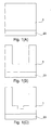
- FIG. 1 shows, in a greatly simplified, schematic representation, various processing stages of a workpiece in the form of an injection mold for an injection molding machine.
- Reference numeral 1 denotes the workpiece, which first as a blank according to FIG. 1 (A) forms the starting point for the manufacturing process.
- Reference numeral 23 denotes a pallet serving as a support base for the workpiece 1 in the different processing devices. After the finishing of the workpiece 1, the workpiece 1 is separated from the pallet 23.
- FIGS. 1 (A) -1 (C) show highly simplified schematic illustrations.
- workpieces 1 are supplied to a plurality of individual processing stations (drilling stations, milling stations, wire erosion stations, grinding stations, polishing stations, etc.).
- processing stations milling stations, milling stations, wire erosion stations, grinding stations, polishing stations, etc.
- a large number of identical or even different workpieces are processed as part of a production process.
- Reference numeral 3 denotes a magazine which is e.g. a total of six workpiece locations 2 includes.
- Each workpiece space 2 is intended to receive a pallet 23 with one or more workpieces to be processed in the production process.
- the arrow in Fig. 2 indicates that the pallets 23 can be removed from the magazine 3.
- each workpiece space 2 Assigned to each workpiece space 2 is a means for status determination of the relevant workpiece location, preferably in accordance with FIG. 2 in the form of a so-called reading antenna 9.
- a control unit 4 which is supplied with electrical power via a power supply unit 7.
- an accumulator 6 is provided, which ensures the power supply or ensures a power supply in case of power failure.
- the system further comprises a data processing unit 5, e.g. a server communicating with the control unit 4 via a suitable data connection.
- This data connection is expediently a network connection, in particular a wireless LAN (WLAN) connection.
- WLAN wireless LAN
- the production data are centrally managed and delivered from there to the relevant process units, in particular processing units.
- the magazine 3 comprises, at each workpiece location 2, a reading antenna 9 assigned to the relevant workpiece location 2, which is capable of a workpiece inserted on the respective workpiece location 2 via its transponder 10, which is permanently fixed in the embodiment of Figure 3 to the total of four workpieces 1 receiving pallet 23 to identify.
- the reader antenna 9 is expediently one which is capable of reading transponder chips (RFID chips) of 125 kHz technology.
- the reading antenna 9 can be fastened in a simple manner at a suitable distance from the workpiece space 2 or workpiece 1 on the magazine 3.
- Each workpiece space 2 is equipped with a corresponding reading antenna 9.
- All reading antennas 9 of the magazine 3 are preferably connected in a series connection or stub line via an interface 11 to the control unit 4 (FIG. 2).
- the relevant reading antenna 9 scans the transponder 10 of the pallet 23 located on the associated workpiece space 2.
- Each reader antenna has an optical status indicator 14 in the form of two LEDs 18, 19.
- the LED 18 lights green, for example, the LED 19 lights red, for example.
- the operating display 14 informs the operator about the respective status of the workpiece location 2.
- the optical display 14 in the form of the two LEDs 18, 19 and the reading antenna 9 are expediently provided as an encapsulated unit and arranged at a suitable location in the region of the associated workpiece space 2, e.g. glued.
- the control unit 4 shows a more detailed representation of the control unit 4 controlling the individual workpiece locations.
- the control unit 4 comprises a microprocessor 20 which, on the one hand, queries the individual reading antennas 9 on the magazine 3 and, on the other hand, prepares the information requested by the magazine 3 and transmits them via a Data connection, in the present case via a network 8 eg via WLAN to the data processing unit 5, not shown in Fig. 5 outputs.
- the power supply of the control unit 4 via the power supply 7 or optionally, As already described above, via the accumulator 6.
- the individual reader antennas 9 are connected to the interface 11 of the control unit 4 via a (not shown) stub.
- the control unit 4 on the one hand controls the reading antennas 9 and on the other hand communicates them with the data processing unit 5, which functions as a status data generator, manager and control center.
- one or more magazines 3 may be connected via respective interfaces with the microprocessor 20 of the control unit 4.
- the individual reading antennas are networked with each other in the manner of a chain with preferably the same length of cable and connected to the interface 11 of the control unit 4.
- the control unit 4 is installed in a separate housing and is firmly connected to the tool carrier 3 or other (not shown) 3 magazines.
- control unit 4 may comprise a plurality, in particular at least five, interfaces, with one magazine 3 per interface having up to forty reading antennas 9, i. Workpiece places 2 are connected. With five communication interfaces, a total of 200 reading antennas 9, which can be controlled by the control unit 4, results.
- the serial interface 12 is preferably used for basic configuration of the control unit 4 and for diagnostic purposes of the system.
- the communication interface follows 802.11b.
- an Ethernet interface 13 is provided, via which a data connection to a data processing unit 5 is likewise possible.
- a plurality of functional units 15, 16 and 17, each consisting of a magazine 3 and a control unit 4 per functional unit are provided, wherein the individual functional units 15, 16 and 17 are connected via their associated control unit 4 via a network 8 e.g. communicate with the data processing unit 5 via WLAN.
- the individual functional units may possibly even be used at different locations.
- the above-described system comprises an optical device (not shown in the drawing figures) for detecting the dimension of the workpiece 1 and / or the positioning of the workpiece 1 relative to the pallet 23. These data are likewise supplied to the data processing unit 5. Based on this information, it is possible to detect whether or not an adjacent workpiece space 2 needs to be kept free, for example due to an excessive dimension of the workpiece 1 in question.
- Such optical detection devices may be located at each workpiece location.
- a movable device can be provided, which can be connected to each workpiece space 2.
- a workpiece location alone or a group or a plurality of workpiece locations combined into a group can be made to be movable in relation to the magazine 3.
- the tool space may be on a carriage or runner so that it can be easily moved from a particular location in a factory to another location where the workpiece space is needed. The same applies to a group of several workpiece locations.
- Red LED Green LED importance Out Out There is no workpiece inserted Out One There is a workpiece inserted. This may be taken One Out There is a workpiece inserted. However, this must not be removed. It is locked One One
- the reader antenna is currently active and tries to read the transponder of a workpiece. This process takes about 100 milliseconds
- the present invention makes it possible to ensure a system for the computer-aided organization of workpieces to be machined in a production process with regard to the speed of the machining processes on the one hand and on the other hand high production reliability.
- the invention therefore represents a very significant contribution in the relevant field of technology.
Landscapes
- Engineering & Computer Science (AREA)
- General Engineering & Computer Science (AREA)
- Manufacturing & Machinery (AREA)
- Quality & Reliability (AREA)
- Physics & Mathematics (AREA)
- General Physics & Mathematics (AREA)
- Automation & Control Theory (AREA)
- General Factory Administration (AREA)
Applications Claiming Priority (1)
| Application Number | Priority Date | Filing Date | Title |
|---|---|---|---|
| DE102006039207A DE102006039207B3 (de) | 2006-08-22 | 2006-08-22 | System sowie Verfahren zur Organisation von zu bearbeitenden Werkstücken |
Publications (2)
| Publication Number | Publication Date |
|---|---|
| EP1892596A2 true EP1892596A2 (fr) | 2008-02-27 |
| EP1892596A3 EP1892596A3 (fr) | 2010-04-14 |
Family
ID=38740500
Family Applications (1)
| Application Number | Title | Priority Date | Filing Date |
|---|---|---|---|
| EP07015673A Withdrawn EP1892596A3 (fr) | 2006-08-22 | 2007-08-09 | Système et procédé destinés à l'organisation de pièces à usiner à traiter |
Country Status (3)
| Country | Link |
|---|---|
| US (1) | US7729793B2 (fr) |
| EP (1) | EP1892596A3 (fr) |
| DE (1) | DE102006039207B3 (fr) |
Families Citing this family (7)
| Publication number | Priority date | Publication date | Assignee | Title |
|---|---|---|---|---|
| US8280544B2 (en) * | 2009-11-02 | 2012-10-02 | Mold Masters (2007) Limited | System for use in performance of injection molding operations |
| US20110106285A1 (en) * | 2009-11-02 | 2011-05-05 | Mold-Masters (2007) Limited | System for use in performance of injection molding operations |
| JP2011098808A (ja) * | 2009-11-05 | 2011-05-19 | Nikon Corp | 基板カートリッジ、基板処理装置、基板処理システム、基板処理方法、制御装置及び表示素子の製造方法 |
| DE102009057906A1 (de) * | 2009-12-11 | 2011-06-16 | Dula-Werke Dustmann & Co. Gmbh | Verfahren zur automatisierten Herstellung von Halbzeugen und Produkten, insbesondere in Individual- und/oder Einzelfertigung |
| US8425216B2 (en) | 2011-03-11 | 2013-04-23 | Mold-Masters (2007) Limited | Cycle counting system for injection molding assembly |
| JP5494617B2 (ja) * | 2011-10-26 | 2014-05-21 | 株式会社安川電機 | ロボットシステムおよび加工品の製造方法 |
| DE102017120381A1 (de) * | 2017-09-05 | 2019-03-07 | Trumpf Werkzeugmaschinen Gmbh + Co. Kg | Assistiertes zuordnen eines werkstücks zu einer mobileinheit eines innenraum-ortungssystems |
Family Cites Families (18)
| Publication number | Priority date | Publication date | Assignee | Title |
|---|---|---|---|---|
| JPS56139862A (en) * | 1980-04-03 | 1981-10-31 | Toshiba Mach Co Ltd | Operation control system of machine tool group |
| US4484289A (en) * | 1982-01-29 | 1984-11-20 | Rapistan Division Of Lear Siegler, Inc. | Tote director |
| DE3234345A1 (de) * | 1982-09-16 | 1984-03-22 | Robert Bosch Gmbh, 7000 Stuttgart | Kodiersystem zur erfassung von informationen an werkstuecktraegern und dergleichen |
| JPS62282848A (ja) * | 1986-05-30 | 1987-12-08 | Tokyo Keiki Co Ltd | Faシステムのデ−タ処理装置 |
| JPS63188247A (ja) * | 1987-01-30 | 1988-08-03 | Yokogawa Electric Corp | メモリ・アクセス装置 |
| US5399531A (en) * | 1990-12-17 | 1995-03-21 | United Micrpelectronics Corporation | Single semiconductor wafer transfer method and plural processing station manufacturing system |
| JPH05261649A (ja) * | 1992-03-17 | 1993-10-12 | Fujitsu Ltd | 投入制御方式 |
| US5798693A (en) * | 1995-06-07 | 1998-08-25 | Engellenner; Thomas J. | Electronic locating systems |
| US5984498A (en) * | 1996-11-21 | 1999-11-16 | Quantum Conveyor Systems, Inc. | Device controller with intracontroller communication capability, conveying system using such controllers for controlling conveying sections and methods related thereto |
| US5920287A (en) * | 1997-01-21 | 1999-07-06 | Widata Corporation | Radio location system for precisely tracking objects by RF transceiver tags which randomly and repetitively emit wideband identification signals |
| US5915231A (en) * | 1997-02-26 | 1999-06-22 | Micron Technology, Inc. | Method in an integrated circuit (IC) manufacturing process for identifying and redirecting IC's mis-processed during their manufacture |
| US5856923A (en) * | 1997-03-24 | 1999-01-05 | Micron Technology, Inc. | Method for continuous, non lot-based integrated circuit manufacturing |
| TW469483B (en) * | 1999-04-19 | 2001-12-21 | Applied Materials Inc | Method and apparatus for aligning a cassette |
| US6714121B1 (en) * | 1999-08-09 | 2004-03-30 | Micron Technology, Inc. | RFID material tracking method and apparatus |
| US6308107B1 (en) * | 1999-08-31 | 2001-10-23 | Advanced Micro Devices, Inc. | Realtime decision making system for reduction of time delays in an automated material handling system |
| US6889109B1 (en) * | 2000-11-03 | 2005-05-03 | Ford Motor Company | Method for maintaining the quality of produced products |
| FR2817684B1 (fr) * | 2000-12-05 | 2006-03-17 | Gemplus Card Int | Dispositif d'antennes pour la lecture d'etiquettes electroniques et systeme incluant un tel dispositif |
| US6754557B2 (en) * | 2001-09-20 | 2004-06-22 | The Tech Group | System and method for manufacturing plastic injection stack components |
-
2006
- 2006-08-22 DE DE102006039207A patent/DE102006039207B3/de not_active Expired - Fee Related
-
2007
- 2007-08-09 EP EP07015673A patent/EP1892596A3/fr not_active Withdrawn
- 2007-08-21 US US11/894,796 patent/US7729793B2/en not_active Expired - Fee Related
Also Published As
| Publication number | Publication date |
|---|---|
| EP1892596A3 (fr) | 2010-04-14 |
| US7729793B2 (en) | 2010-06-01 |
| DE102006039207B3 (de) | 2008-04-03 |
| US20080097642A1 (en) | 2008-04-24 |
Similar Documents
| Publication | Publication Date | Title |
|---|---|---|
| EP1892596A2 (fr) | Système et procédé destinés à l'organisation de pièces à usiner à traiter | |
| DE102016209557B4 (de) | Verfahren zur Identifizierung eines Werkstücks, Ermitteln eines Messablaufs und Vermessung eines Werkstücks mit einem Messgerät | |
| EP0491657B1 (fr) | Dispositif de fabrication automatique | |
| EP2670543B1 (fr) | Dispositif de fabrication comportant des moyens de détection de position d'outil et son procédé de fonctionnement | |
| DE202013012320U1 (de) | Honmaschine mit mehreren Arbeitsstationen und Rundtisch | |
| EP3715047A2 (fr) | Système pour usiner des pièces | |
| DE60219267T2 (de) | Greifeinheit für die automatisierte Bearbeitung von Werkstücken, und Vorrichtung und Verfahren mit einer solchen Einheit | |
| DE102019105745A1 (de) | Produktionsmanagementsystem | |
| DE102019124428A1 (de) | Vorrichtung zur, insbesondere automatisierten, Bereitstellung eines Komplettwerkzeugs | |
| DE102021209011A1 (de) | Produktionseinrichtung | |
| DE102019130885A1 (de) | Arbeitsverteilungssystem und Arbeitsverteilungsverfahren zur Formenherstellung | |
| DE102008021997B4 (de) | Plattenaufteilanlage | |
| EP2700596A1 (fr) | Système de préparation de commandes | |
| DE102010034167A1 (de) | System und Verfahren zum Bearbeiten von Sicherheits- oder Identifikationsgegenständen | |
| DE102006024904B4 (de) | Verfahren zum Bereitstellen von Werkzeugen für das Herstellen und/oder Bearbeiten von Gegenständen, wobei den Werkzeugen und Ablageorten Identifikationen zugeordnet werden | |
| DE10306856B4 (de) | Verfahren und System zum Fertigen eines komplexen Gegenstands, bei denen Änderungen der Eigenschaftsdaten ohne einen manuellen Eingriff zu den lokalen Fertigungseinheiten gelangen können | |
| EP4596173A1 (fr) | Procédé avec un appareil de réglage et/ou de mesure d'outil, appareil de réglage d'outil et/ou de mesure d'outil, appareil de serrage d'outil et produit programme informatique | |
| DE202019106365U1 (de) | Arbeitsverteilungssystem zur Formenherstellung | |
| DE102017124571B4 (de) | Halte- und Antriebseinrichtung, Werkzeugeinrichtung, Ergänzungswerkzeugeinrichtung von einer modular aufgebauten Bauelement-Handhabungsvorrichtung, Vorrichtung zum Handhaben von Bauelementen sowie Verfahren zum anwendungsspezifischen Konfigurieren einer solchen Vorrichtung | |
| DE19844797C2 (de) | Fertigungs- und/oder Montagevorrichtung | |
| AT521971A4 (de) | Verfahren zum Bearbeiten, insbesondere Zertrennen, wenigstens eines Betonteils | |
| WO1999012440A2 (fr) | Dispositif de commande d'une machine automatique de production et dispositif de serrage des pieces a usiner | |
| WO2023036649A1 (fr) | Dispositif de production et/ou d'usinage d'objets et procédé de production et/ou d'usinage d'un objet | |
| DE102022100201A1 (de) | Allgemeine Plattform zum Verarbeiten von Werkstücken | |
| DE102025104096B3 (de) | Steuerungssystem einer werkzeugmaschine, palettensystem mit freigabedaten und verfahren zur bearbeitungsfreigabe |
Legal Events
| Date | Code | Title | Description |
|---|---|---|---|
| PUAI | Public reference made under article 153(3) epc to a published international application that has entered the european phase |
Free format text: ORIGINAL CODE: 0009012 |
|
| AK | Designated contracting states |
Kind code of ref document: A2 Designated state(s): AT BE BG CH CY CZ DE DK EE ES FI FR GB GR HU IE IS IT LI LT LU LV MC MT NL PL PT RO SE SI SK TR |
|
| AX | Request for extension of the european patent |
Extension state: AL BA HR MK YU |
|
| PUAL | Search report despatched |
Free format text: ORIGINAL CODE: 0009013 |
|
| AK | Designated contracting states |
Kind code of ref document: A3 Designated state(s): AT BE BG CH CY CZ DE DK EE ES FI FR GB GR HU IE IS IT LI LT LU LV MC MT NL PL PT RO SE SI SK TR |
|
| AX | Request for extension of the european patent |
Extension state: AL BA HR MK RS |
|
| RIC1 | Information provided on ipc code assigned before grant |
Ipc: G05B 19/418 20060101AFI20071206BHEP Ipc: G06Q 10/00 20060101ALI20100311BHEP Ipc: G06K 19/07 20060101ALI20100311BHEP |
|
| 17P | Request for examination filed |
Effective date: 20101014 |
|
| AKX | Designation fees paid |
Designated state(s): AT BE BG CH CY CZ DE DK EE ES FI FR GB GR HU IE IS IT LI LT LU LV MC MT NL PL PT RO SE SI SK TR |
|
| 17Q | First examination report despatched |
Effective date: 20111103 |
|
| RAP1 | Party data changed (applicant data changed or rights of an application transferred) |
Owner name: CERTA SYSTEMS GMBH |
|
| STAA | Information on the status of an ep patent application or granted ep patent |
Free format text: STATUS: THE APPLICATION IS DEEMED TO BE WITHDRAWN |
|
| 18D | Application deemed to be withdrawn |
Effective date: 20180301 |