EP1892598A2 - Système d'automatisation et procédé pour optimiser des temps de cycle, des processus et/ou des machines - Google Patents
Système d'automatisation et procédé pour optimiser des temps de cycle, des processus et/ou des machines Download PDFInfo
- Publication number
- EP1892598A2 EP1892598A2 EP07010198A EP07010198A EP1892598A2 EP 1892598 A2 EP1892598 A2 EP 1892598A2 EP 07010198 A EP07010198 A EP 07010198A EP 07010198 A EP07010198 A EP 07010198A EP 1892598 A2 EP1892598 A2 EP 1892598A2
- Authority
- EP
- European Patent Office
- Prior art keywords
- data processing
- automation system
- processing levels
- data
- time
- Prior art date
- Legal status (The legal status is an assumption and is not a legal conclusion. Google has not performed a legal analysis and makes no representation as to the accuracy of the status listed.)
- Withdrawn
Links
Images


Classifications
-
- G—PHYSICS
- G05—CONTROLLING; REGULATING
- G05B—CONTROL OR REGULATING SYSTEMS IN GENERAL; FUNCTIONAL ELEMENTS OF SUCH SYSTEMS; MONITORING OR TESTING ARRANGEMENTS FOR SUCH SYSTEMS OR ELEMENTS
- G05B19/00—Program-control systems
- G05B19/02—Program-control systems electric
- G05B19/18—Numerical control [NC], i.e. automatically operating machines, in particular machine tools, e.g. in a manufacturing environment, so as to execute positioning, movement or co-ordinated operations by means of program data in numerical form
- G05B19/4155—Numerical control [NC], i.e. automatically operating machines, in particular machine tools, e.g. in a manufacturing environment, so as to execute positioning, movement or co-ordinated operations by means of program data in numerical form characterised by program execution, i.e. part program or machine function execution, e.g. selection of a program
-
- G—PHYSICS
- G05—CONTROLLING; REGULATING
- G05B—CONTROL OR REGULATING SYSTEMS IN GENERAL; FUNCTIONAL ELEMENTS OF SUCH SYSTEMS; MONITORING OR TESTING ARRANGEMENTS FOR SUCH SYSTEMS OR ELEMENTS
- G05B2219/00—Program-control systems
- G05B2219/30—Nc systems
- G05B2219/36—Nc in input of data, input key till input tape
- G05B2219/36301—Optimisation of sequence of operations
Definitions
- the present invention relates to an automation system and a method for cycle time, process and / or machine optimization.
- a known problem in the design and commissioning of automation systems is the maintenance or optimization of the total cycle time taking into account the cycle times of individual processes within the various subsystems, such as PLC, NC, drive, etc.
- Such automation systems generate data on different time levels and / or in different subsystems.
- An optimization of such automation systems by means of a reduction of the cycle times, in which case both the overall sequence and partial sequences are included, is aimed for.
- the various subsystems such as PLC, NC, or drives
- CNC-sided there is no tool; that collects and / or displays data isochronously on the different time levels.
- tools known which provide higher-level indication of the cycle times and, if necessary, provide specific subsystem data (such as the drive-side motor current or state of a PLC flag) or synchronous graphical simulation as needed.
- the oscilloscope function of a drive only takes into account data of the drive, and in this context only provides special representations the data.
- the data recorded there are with the existing there Times saved.
- a synchronization of these clocks with the clocks of other subsystems is not given in the rule.
- the data is not related to the cycle times of other subsystems or the overall (specified by the NC program) overall sequence.
- cycle time analysis tools are known in which the data is captured on a PC via a respective control interface.
- the relevant data for example, current NC block or current motor current
- the controller on change or cyclically and provided with a time stamp on the PC side.
- temporal variations of up to one second are unavoidable in typical applications.
- short operations lasting less than one second are not reliably detectable.
- isochronous recording of data over different time levels and subsystems in automation systems it is desirable to provide isochronous recording of data over different time levels and subsystems in automation systems.
- a visualization of the relevant data is sought in order to provide an overview of the cycle times.
- an isochronous visualization of the recorded data in terms of cycle time, process and / or machine optimization is sought.
- the invention provides for this purpose for a Aütomatmaschinessystem a method for Taktzeit-, process and / or machine optimization with the features of the independent claims.
- Advantageous' embodiments are the subject of the dependent claims and the following description.
- an isochronous data acquisition over the different time levels of the CNC control of an automation system for example, provided on the levels of sentence preparation and sentence processing.
- This allows, in particular, a visualization of the acquired data in temporal relation to one another.
- This makes it possible, in addition to the interpretation time, the block preparation time, the block processing time (and thus also the time between block preparation and block execution) with relevant, the cycle time influencing processes on the NC, the PLC or on a drive (eg the acceleration / Braking phases in the form of the current axis acceleration and / or motor current).
- the user is able to correlate the individual processes within the automation system with each other and, in particular, with the overall process (such as the NC program).
- the automation system according to the invention has means for visualizing the determined cycle times.
- Such a visualization makes it possible for a programmer, commissioning person or machine operator of the system to recognize in a particularly simple manner where savings potential can exist or at which points optimizations are possible.
- means for regularly or selectively applying and / or querying the clock time detection means are provided.
- the individual optimization steps during commissioning can be easily checked for their effectiveness. In the same way it can be determined during the later operation of the automation system, whether it decreases over time in its effectiveness. Furthermore, it is possible to incorporate the knowledge gained in the course of operation of the automation system in a new clock time detection.
- the internal and / or external subsystems drive, PLC, NC, and / or RC systems.
- An inventive coordination of such systems leads to particularly large savings.
- the clock time detection means are designed as internal clocks synchronized with one another via the individual subsystems (hardware limits). Such clocks are typically included in automation systems, but not synchronized with each other, so that although events on the various sub-textures are detected with ⁇ s precision, they can not be related to each other in a ⁇ s-precise manner.
- FIG. 1 describes the basic principle of a CNC control.
- the NC program of a not shown in detail CNC control is shown schematically and designated 100.
- the program When calling the NC program 100 by the controller, the program, in a conventional manner, from a Memory loaded into a RAM.
- the NC program for example, provides a sequence for a robotic system.
- the data loaded into the RAM are first subjected to a sentence preparation SAV, designated 150.
- This sentence preparation 150 represents a first temporal level of the NC program, which typically takes place in the millisecond range.
- the goal of the sentence preparation 150 is a processing of the data provided by the NC program 100, wherein with these processed NC data sets an interpolator IPO (denoted by 160) must be feasible, which takes place in the microsecond range or in real time.
- This interpolator activity 160 represents a second temporal level within the overall system. It should be noted that this coarse subdivision into two time levels is merely illustrative of the invention. Actually realized systems may have a multiplicity of such levels, as will be illustrated below with reference to FIG.
- Typical applications or preparations in the context of sentence preparation 150 are the admission of the data of the NC program 100 with basic command sets or movement commands, for example according to DIN 66025 (reference numeral 152). Furthermore, a customization of the customer-programming language (CPL sentences) can take place here (represented by 154). Insert sets (labeled 156), for example, inserts the sentence editor when tool radius compensation is turned on and a corner is bypassed. In such a case, the sentence editor inserts a circle segment as an intermediate sentence.
- CPL sentences customer-programming language
- the sentence preparation 150 comprises an overall interpretation 158 of the data received from the NC program 100 as well as a sentence preparation 157. Interpretation and sentence preparation may partially run parallel. However, it is also possible to execute the sentence preparation 157 after completion of the interpretation 158.
- the data or data records generated as part of the sentence processing are, as already mentioned, processed in the interpolator device 160 (step 166).
- the beginning of the interpolation (by means of clock 123) and the end of the interpolation (by means of clock 124) are recorded in terms of time, preferably once again by means of timestamps generated by synchronized clocks.
- the data generated as part of the block preparation or block preparation can be temporarily stored in a memory for prepared NC blocks (shown schematically in FIG. 1 and designated by 159).
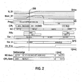
- the line "PROG” is, for example, the main program (NC program) which calls corresponding subprograms, for example M6, which initiates a tool change.
- NC program which calls corresponding subprograms, for example M6, which initiates a tool change.
- Other subprograms or variables are with the other abbreviations CPL (already mentioned), NC (NC block), Hifu (auxiliary functions for fast data exchange between NC and PLC (memory programming control), Var_1 (variable of the NC), Var_A (variable of the PLC
- a cursor 200 which for example is continuously displaceable along the respective lines, a comparative consideration of the cycle times or control times resulting in the individual lines can be realized Measuring cursors are used, for example, to measure times of a particular operation relative to the overall process, such as the acceleration phase of a drive at the beginning of a particular processing sequence.
- NC blocks are displayed in the NC line.
- the NC block N0010 takes a relatively long time.
- the execution time of this block could be reduced by setting the channel enable (Ch_Ena on the PLC) early.
- the moment characteristic does not seem to be optimal (see Fig. 2, Mom_X1).
- the acceleration torque of the axis in the acceleration and braking phase should be examined in more detail next. Further potential savings can u.U. reach during spindle run-up (N_S1).
- Checking the sub-processes controlled via the auxiliary functions M40, M71 and M88 may provide (by a closer analysis) also saving potential.
- process M71 "Open tool gripper" on the PLC may be set a little earlier after specific monitoring has been performed, thus requiring slightly less head time to drive the hydraulic valve to open a tool gripper. Another possibility may exist. This means that the auxiliary function M71 already outputs an NC block earlier.
- the NC set or selected CPL set selected via the cursor is displayed as well as the respective execution time.
- cycle time analysis can be characterized by simultaneous recording of the motor encoder and the external encoder, directly the machine compliance during processing (if necessary, also over the entire machining process away), save, display, assess and, if necessary, optimize.
- the recording is switched on optionally by means of a command in the NC program 100, such as OSC (1) or via a suitable, not shown surface by means of a button.
- a command for recording NC blocks and / or record-related or non-record-related signals (including corresponding trigger conditions) is issued by a subsystem of the control system, the NC activates the data (signals) specified by the user (signals) required start (102), modal (104) and exit (106) jobs to record the data at the various levels of the control system.
- a startup job (with the functions OscOnStart and Os-cOnIpoBlk) the required for the recording Preparations, such as requesting memory, or performing address calculations for the data to be recorded.
- the various levels or functions of the startup job 102 are indicated schematically and at 102a, 102b.
- FIG. 3 shows, by way of example, a number of modal functions relevant to the recording (OscPrep, SaveBlkData, OscEndOfPrep and OscPärser) 104a to 104d of the modal job 104.
- block processing 166 'and interpolator 160 and, if necessary, also on the other subsystems such as SPS.and drives), they do not draw the data selected by the user, including the associated time stamps, by means of clock-synchronized clocks (in FIG shown).
- the path velocity and, at the interpolator level, the current axis velocity are recorded with the associated time stamps.
- the NC executes the exit job (106) OscOffIpoBlk, which releases temporary memory, for example.
- the recording is aborted.
- the NC executes another start job 108 OscOffStart and in particular removes the modal jobs 104.
- An area Ctrl (reference numeral 159a) is used to configure the recording, such as the presetting of the signals or the time frame in which the signals or data are to be recorded.
- An area BlPrepOszi (159b) represents the memory in which the data and signals obtained at record preparation levels are stored.
- IpoOszi (159c) stores the data and signals on the interpolator.
- the two last-mentioned memories can also be realized in the form of an exchange buffer in order to be able to record larger amounts of data with a high sampling rate within the NC even over longer periods of time.
- connection of other systems involved in a recording is carried out by the transmission of the trigger signal between the systems.
- An essential requirement for cross-subsystem clock-synchronous recording are the clocks synchronized with each other across the subsystem boundaries.
- a tool or tool according to the invention is provided, with the aid of which clock-time-relevant data are recorded, stored, managed, processed and graphically displayed in a wide variety of ways.
- a very high accuracy of the time recording is realized.
- Data on all time levels The controller can be captured and recorded (not just IPO data).
- a temporal reference can be provided over all time levels, in particular via synchronized clocks present in the overall system, and can be visualized accordingly by the graphical processing. With this, recorded set information and other recorded data and signals of the various control levels can be displayed synchronously.
- a time-synchronized graphical processing simulation may be included as needed, which may include, for example, forward or backward-directed sentence progression.
Landscapes
- Engineering & Computer Science (AREA)
- Human Computer Interaction (AREA)
- Manufacturing & Machinery (AREA)
- Physics & Mathematics (AREA)
- General Physics & Mathematics (AREA)
- Automation & Control Theory (AREA)
- Numerical Control (AREA)
- Signal Processing For Digital Recording And Reproducing (AREA)
Applications Claiming Priority (1)
| Application Number | Priority Date | Filing Date | Title |
|---|---|---|---|
| DE102006039244A DE102006039244A1 (de) | 2006-08-22 | 2006-08-22 | Automatisierungssystem und Verfahren zur Taktzeit-, Prozess- und/oder Maschinenoptimierung |
Publications (2)
| Publication Number | Publication Date |
|---|---|
| EP1892598A2 true EP1892598A2 (fr) | 2008-02-27 |
| EP1892598A3 EP1892598A3 (fr) | 2010-03-03 |
Family
ID=38686745
Family Applications (1)
| Application Number | Title | Priority Date | Filing Date |
|---|---|---|---|
| EP07010198A Withdrawn EP1892598A3 (fr) | 2006-08-22 | 2007-05-23 | Système d'automatisation et procédé pour optimiser des temps de cycle, des processus et/ou des machines |
Country Status (4)
| Country | Link |
|---|---|
| US (1) | US9547302B2 (fr) |
| EP (1) | EP1892598A3 (fr) |
| JP (1) | JP2008052738A (fr) |
| DE (1) | DE102006039244A1 (fr) |
Cited By (3)
| Publication number | Priority date | Publication date | Assignee | Title |
|---|---|---|---|---|
| EP2434357A1 (fr) * | 2010-09-22 | 2012-03-28 | Siemens Aktiengesellschaft | Système d'enregistrement de données technologiques et/ou d'événements du programme |
| EP2434360A1 (fr) * | 2010-09-22 | 2012-03-28 | Siemens Aktiengesellschaft | Système de contrôle de mouvement |
| CN119057560A (zh) * | 2024-09-29 | 2024-12-03 | 东风商用车有限公司 | 数控机床数据同步方法、装置、数控机床及存储介质 |
Families Citing this family (3)
| Publication number | Priority date | Publication date | Assignee | Title |
|---|---|---|---|---|
| CN108490876B (zh) * | 2018-02-11 | 2020-10-23 | 西南交通大学 | 一种提高数控加工监控阈值与信号同步精确性的方法 |
| US11351669B2 (en) * | 2019-10-29 | 2022-06-07 | Kyndryl, Inc. | Robotic management for optimizing a number of robots |
| CN115421447B (zh) * | 2022-08-20 | 2024-06-21 | 山东科技大学 | 数控机床时间-能量效率评估与控制方法、系统及装置 |
Citations (3)
| Publication number | Priority date | Publication date | Assignee | Title |
|---|---|---|---|---|
| EP0104503A2 (fr) | 1982-09-03 | 1984-04-04 | Mitsubishi Denki Kabushiki Kaisha | Système de commande numérique et machine-outil comprenant ce système |
| DE19746130A1 (de) | 1997-10-18 | 1999-04-22 | Index Werke Kg Hahn & Tessky | Werkzeugmaschine |
| DE102004052555A1 (de) | 2004-10-29 | 2006-05-04 | Bosch Rexroth Ag | Verfahren zum Austauschen von Daten zwischen Teilnehmern aus verschiedenen Netzwerken |
Family Cites Families (11)
| Publication number | Priority date | Publication date | Assignee | Title |
|---|---|---|---|---|
| US4310878A (en) * | 1970-12-28 | 1982-01-12 | Hyatt Gilbert P | Digital feedback control system |
| US4864205A (en) * | 1987-10-09 | 1989-09-05 | Hewlett-Packard Company | Method for coordinated control of motion devices |
| US5483468A (en) * | 1992-10-23 | 1996-01-09 | International Business Machines Corporation | System and method for concurrent recording and displaying of system performance data |
| US6993695B2 (en) * | 2001-06-06 | 2006-01-31 | Agilent Technologies, Inc. | Method and apparatus for testing digital devices using transition timestamps |
| US6788218B2 (en) * | 2001-07-19 | 2004-09-07 | Lancer Partnership, Ltd. | Pseudo real-time diagnostic and process monitoring system |
| US6757583B2 (en) * | 2002-06-27 | 2004-06-29 | Joe Giamona | Interpolated motion control over a serial network |
| US7580037B1 (en) * | 2003-09-05 | 2009-08-25 | Altera Corporation | Techniques for graphical analysis and manipulation of circuit timing requirements |
| US7500152B2 (en) * | 2003-12-05 | 2009-03-03 | Freescale Semiconductor, Inc. | Apparatus and method for time ordering events in a system having multiple time domains |
| DE10357824A1 (de) * | 2003-12-09 | 2005-07-14 | Kuka Roboter Gmbh | Verfahren und Vorrichtung zum Betreiben zusammenarbeitender unterschiedlicher Geräte |
| WO2009068034A1 (fr) * | 2007-11-26 | 2009-06-04 | Vestas Wind Systems A/S | Méthode et système d'enregistrement d'événements relatifs aux éoliennes d'un système d'énergie éolienne |
| US7453910B1 (en) * | 2007-12-18 | 2008-11-18 | International Business Machines Corporation | Synchronization of independent clocks |
-
2006
- 2006-08-22 DE DE102006039244A patent/DE102006039244A1/de not_active Ceased
-
2007
- 2007-05-23 EP EP07010198A patent/EP1892598A3/fr not_active Withdrawn
- 2007-08-01 US US11/832,011 patent/US9547302B2/en not_active Expired - Fee Related
- 2007-08-22 JP JP2007216187A patent/JP2008052738A/ja active Pending
Patent Citations (3)
| Publication number | Priority date | Publication date | Assignee | Title |
|---|---|---|---|---|
| EP0104503A2 (fr) | 1982-09-03 | 1984-04-04 | Mitsubishi Denki Kabushiki Kaisha | Système de commande numérique et machine-outil comprenant ce système |
| DE19746130A1 (de) | 1997-10-18 | 1999-04-22 | Index Werke Kg Hahn & Tessky | Werkzeugmaschine |
| DE102004052555A1 (de) | 2004-10-29 | 2006-05-04 | Bosch Rexroth Ag | Verfahren zum Austauschen von Daten zwischen Teilnehmern aus verschiedenen Netzwerken |
Cited By (4)
| Publication number | Priority date | Publication date | Assignee | Title |
|---|---|---|---|---|
| EP2434357A1 (fr) * | 2010-09-22 | 2012-03-28 | Siemens Aktiengesellschaft | Système d'enregistrement de données technologiques et/ou d'événements du programme |
| EP2434360A1 (fr) * | 2010-09-22 | 2012-03-28 | Siemens Aktiengesellschaft | Système de contrôle de mouvement |
| EP2434357B1 (fr) | 2010-09-22 | 2020-02-12 | Siemens Aktiengesellschaft | Système d'enregistrement de données technologiques et/ou d'événements du programme |
| CN119057560A (zh) * | 2024-09-29 | 2024-12-03 | 东风商用车有限公司 | 数控机床数据同步方法、装置、数控机床及存储介质 |
Also Published As
| Publication number | Publication date |
|---|---|
| JP2008052738A (ja) | 2008-03-06 |
| US9547302B2 (en) | 2017-01-17 |
| EP1892598A3 (fr) | 2010-03-03 |
| DE102006039244A1 (de) | 2008-03-06 |
| US20080052554A1 (en) | 2008-02-28 |
Similar Documents
| Publication | Publication Date | Title |
|---|---|---|
| EP2138914B1 (fr) | Procédé et dispositif d'optimisation, de surveillance ou d'analyse d'un processus | |
| EP2188684B1 (fr) | Machine-outil virtuelle servant à représenter des actions menées par des unités d'usinage d'une machine-outil réelle | |
| EP1901149B1 (fr) | Procédé et dispositif destinés à la simulation de l'usinage d'une pièce sur une machine-outil | |
| EP2435884B1 (fr) | Machine-outil virtuelle servant à représenter des actions menées par des unités d'usinage et à produire des données de fonctionnement à partir d'entrées d'utilisateur | |
| DE102017009822A1 (de) | Maschinenlernvorrichtung und Bearbeitungszeitvorhersagevorrichtung | |
| EP2419799A1 (fr) | Procédé de préparation de données d'état de processus et/ou de données d'état de machine d'une machine-outil | |
| EP1989601B1 (fr) | Systeme et procede pour analyser un processus de fabrication | |
| DE112008003800T5 (de) | Numerische Steuerverfahren und Vorrichtung dafür | |
| AT10596U1 (de) | Konfigurierung von maschinenablaufen | |
| EP1892598A2 (fr) | Système d'automatisation et procédé pour optimiser des temps de cycle, des processus et/ou des machines | |
| DE102010017763A1 (de) | Gerät zum Anzeigen des Werkzeugwegs für Werkzeugmaschinen | |
| DE102007045595A1 (de) | Verfahren und virtuelle Werkzeugmaschine zur Darstellung von Aktionen einer realen Werkzeugmaschine | |
| EP2650741B1 (fr) | Machine-outil | |
| DE102017009751A1 (de) | Numerische Steuervorrichtung | |
| DE10308816A1 (de) | Ikone und Schrittikonendarstellung zur graphischen Visualisierung von aufgabenorientierten Schritten | |
| EP0642067B1 (fr) | Système de programmation orientée dialogue pour une machine-outil à CNC | |
| EP2419798A1 (fr) | Procédé permettant d'obtenir une information concernant l'usure d'un composant d'une machine et procédé de préparation d'un algorithme alternatif | |
| DE10261227A1 (de) | Einrichtung zur integrierten Werkzeugfertigung und Verfahren dazu | |
| DE112019006945B4 (de) | Mehrachssteuerungssystem, Mehrachssteuerungsverfahren und Mehrachssteuerungsprogramm | |
| DE4228702A1 (de) | Programmgesteuerte bearbeitungsvorrichtung und verfahren zur ueberwachung ihres betriebes | |
| DE69415612T2 (de) | Verfahren zur fehlerbeseitigung in einem folgesteuerungsprogramm | |
| EP0805382B1 (fr) | Dispositif de diagnostique pour une machine à commande électronique avec clés de combinaison d'états mesurés de la machine | |
| DE102015008297B4 (de) | Numerische Steuerung mit Betrieb durch tabellenformatierte Daten | |
| DE19614201A1 (de) | Verfahren und Vorrichtung zur Steuerung einer Werkzeugmaschine, insbesondere einer Funkenerosionsmaschine | |
| DE102017001171B4 (de) | Numerische Steuervorrichtung |
Legal Events
| Date | Code | Title | Description |
|---|---|---|---|
| PUAI | Public reference made under article 153(3) epc to a published international application that has entered the european phase |
Free format text: ORIGINAL CODE: 0009012 |
|
| AK | Designated contracting states |
Kind code of ref document: A2 Designated state(s): AT BE BG CH CY CZ DE DK EE ES FI FR GB GR HU IE IS IT LI LT LU LV MC MT NL PL PT RO SE SI SK TR |
|
| AX | Request for extension of the european patent |
Extension state: AL BA HR MK YU |
|
| PUAL | Search report despatched |
Free format text: ORIGINAL CODE: 0009013 |
|
| AK | Designated contracting states |
Kind code of ref document: A3 Designated state(s): AT BE BG CH CY CZ DE DK EE ES FI FR GB GR HU IE IS IT LI LT LU LV MC MT NL PL PT RO SE SI SK TR |
|
| AX | Request for extension of the european patent |
Extension state: AL BA HR MK RS |
|
| 17P | Request for examination filed |
Effective date: 20100903 |
|
| 17Q | First examination report despatched |
Effective date: 20101006 |
|
| AKX | Designation fees paid |
Designated state(s): AT BE BG CH CY CZ DE DK EE ES FI FR GB GR HU IE IS IT LI LT LU LV MC MT NL PL PT RO SE SI SK TR |
|
| STAA | Information on the status of an ep patent application or granted ep patent |
Free format text: STATUS: THE APPLICATION IS DEEMED TO BE WITHDRAWN |
|
| 18D | Application deemed to be withdrawn |
Effective date: 20170215 |