EP1892716A1 - Dateischneidevorrichtung, Dateischneideverfahren und Dateischneideprogramm - Google Patents
Dateischneidevorrichtung, Dateischneideverfahren und Dateischneideprogramm Download PDFInfo
- Publication number
- EP1892716A1 EP1892716A1 EP20070110762 EP07110762A EP1892716A1 EP 1892716 A1 EP1892716 A1 EP 1892716A1 EP 20070110762 EP20070110762 EP 20070110762 EP 07110762 A EP07110762 A EP 07110762A EP 1892716 A1 EP1892716 A1 EP 1892716A1
- Authority
- EP
- European Patent Office
- Prior art keywords
- file
- recording
- management
- region
- data
- Prior art date
- Legal status (The legal status is an assumption and is not a legal conclusion. Google has not performed a legal analysis and makes no representation as to the accuracy of the status listed.)
- Granted
Links
Images





Classifications
-
- G—PHYSICS
- G11—INFORMATION STORAGE
- G11B—INFORMATION STORAGE BASED ON RELATIVE MOVEMENT BETWEEN RECORD CARRIER AND TRANSDUCER
- G11B27/00—Editing; Indexing; Addressing; Timing or synchronising; Monitoring; Measuring tape travel
- G11B27/02—Editing, e.g. varying the order of information signals recorded on, or reproduced from, record carriers
- G11B27/06—Cutting and rejoining; Notching, or perforating record carriers otherwise than by recording styli
-
- G—PHYSICS
- G11—INFORMATION STORAGE
- G11B—INFORMATION STORAGE BASED ON RELATIVE MOVEMENT BETWEEN RECORD CARRIER AND TRANSDUCER
- G11B27/00—Editing; Indexing; Addressing; Timing or synchronising; Monitoring; Measuring tape travel
- G11B27/02—Editing, e.g. varying the order of information signals recorded on, or reproduced from, record carriers
- G11B27/031—Electronic editing of digitised analogue information signals, e.g. audio or video signals
- G11B27/034—Electronic editing of digitised analogue information signals, e.g. audio or video signals on discs
-
- G—PHYSICS
- G11—INFORMATION STORAGE
- G11B—INFORMATION STORAGE BASED ON RELATIVE MOVEMENT BETWEEN RECORD CARRIER AND TRANSDUCER
- G11B20/00—Signal processing not specific to the method of recording or reproducing; Circuits therefor
- G11B20/10—Digital recording or reproducing
-
- G—PHYSICS
- G11—INFORMATION STORAGE
- G11B—INFORMATION STORAGE BASED ON RELATIVE MOVEMENT BETWEEN RECORD CARRIER AND TRANSDUCER
- G11B20/00—Signal processing not specific to the method of recording or reproducing; Circuits therefor
- G11B20/10—Digital recording or reproducing
- G11B20/12—Formatting, e.g. arrangement of data block or words on the record carriers
-
- G—PHYSICS
- G11—INFORMATION STORAGE
- G11B—INFORMATION STORAGE BASED ON RELATIVE MOVEMENT BETWEEN RECORD CARRIER AND TRANSDUCER
- G11B27/00—Editing; Indexing; Addressing; Timing or synchronising; Monitoring; Measuring tape travel
- G11B27/02—Editing, e.g. varying the order of information signals recorded on, or reproduced from, record carriers
- G11B27/031—Electronic editing of digitised analogue information signals, e.g. audio or video signals
- G11B27/036—Insert-editing
-
- G—PHYSICS
- G11—INFORMATION STORAGE
- G11B—INFORMATION STORAGE BASED ON RELATIVE MOVEMENT BETWEEN RECORD CARRIER AND TRANSDUCER
- G11B27/00—Editing; Indexing; Addressing; Timing or synchronising; Monitoring; Measuring tape travel
- G11B27/10—Indexing; Addressing; Timing or synchronising; Measuring tape travel
Definitions
- the present invention contains subject matter related to Japanese Patent Application JP 2006-182210 filed in the Japanese Patent Office on June 30, 2006 , the entire contents of which being incorporated herein by reference.
- the present invention relates to a file splitting apparatus, a file splitting method and a file splitting program that can suitably be applied to a video recorder integral with a camera (to be referred to as video camera hereinafter) for picking up an image of a subject as moving image and recording the generated moving image data as data file.
- a video recorder integral with a camera to be referred to as video camera hereinafter
- Known recording/reproduction apparatus are adapted to define a data recording region for recording data files and a management information recording region for recording management information necessary for managing the data files according to a File Allocation Tables (FAT) file system. Additionally, recording/reproduction apparatus are adapted to define a plurality of recording management regions (to be referred to clusters hereinafter) for the data recording region according to the FAT file system and also record a management table for managing recording/reproduction of data files by each part thereof for which management information is recorded in a cluster (to be referred to as cluster recording part hereinafter) of the data files.
- FAT File Allocation Tables
- the recording/reproduction apparatus manages recording/reproduction of data files in the data recording region of a recording medium by mean of the management table, utilizing the FAT file system. Additionally, the recording/reproduction apparatus manages splitting of data files recorded in the data recording region of the recording medium jointly utilizing some other file system defined based on the FAT file system (see, e.g., Jpn. Pat. Appln. Laid-Open Publication No. 2004-5867 )
- the recording/reproduction apparatus records a management table dedicated to the management of splitting of data files, utilizing some other file system.
- the recording/reproduction apparatus secures a management information recording region having an area that is large enough for recording management tables of two different types in the limited recording region of the recording medium.
- the file splitting position may be located midway of the cluster recording part of a cluster. If such is the case and only a FAT file system is adopted, the cluster recording part that includes the file splitting position (to be referred to as splitting position cluster recording part hereinafter) covers both the rear part of the split data file (to be referred to as split data file DFb hereinafter) and the front part of the split data file (to be referred to as split data file DFa hereinafter) obtained by splitting the data file, although the splitting position cluster recording part cannot manage the two parts of the split data file at the same time due to the configuration of a management table.
- splitting position cluster recording part covers both the rear part of the split data file (to be referred to as split data file DFb hereinafter) and the front part of the split data file (to be referred to as split data file DFa hereinafter) obtained by splitting the data file, although the splitting position cluster recording part cannot manage the two parts of the split data file at the same time due to the configuration of a management table.
- the recording/reproduction apparatus when a file splitting position D is located midway of a cluster recording part (the split position cluster recording part) after splitting a data file, the recording/reproduction apparatus where only a FAT file system is adopted moves either of the two split data files DFa and DFb including the front side split data file DFa that precedes the file splitting position D and the rear side split data file DFb that succeeds the file splitting position D to some other recording location, e.g., the rear side split data file DFb, copying the rear side split data file DFb from the split position cluster recording part R down to the tail end cluster recording part of the split data file DFb over a plurality of clusters C that have not been recorded yet.
- some other recording location e.g., the rear side split data file DFb
- the recording/reproduction apparatus deletes the plurality of cluster recording parts for the rear side split data file DFb before the split except the split position cluster recording part R before the copying.
- the recording/reproduction apparatus is required to separate the split data file DFa that is left intact from the leading cluster recording part to the split position cluster recording part R before the copying from the other split data file DFb (that has been moved) and manage them independently according to the management table.
- the recording/reproduction apparatus is required to record the split data file DFb once again to give rise to a problem of cumbersomeness of the process of splitting a data file.
- the present invention has been made in view of the above-mentioned and realizes a file splitting apparatus, a file splitting method and a file splitting program that can execute a data file splitting process in a simplified manner.
- a file splitting apparatus for splitting a data file recorded over a plurality of recording management regions arranged in the recording region of a recording medium
- the apparatus including: a management region recording part detecting section for detecting a management region recording part including a file splitting position out of a plurality of management region recording parts of a plurality of recording management regions of the data file recorded in the recording region at the time of being split at a predetermined file splitting position; a management region recording part copying section for copying the management region recording part including the file splitting position as detected by the management region recording part detecting section to some other recording management region of the recording region; and a management information altering section for altering the management information of the data file to first management information for managing one of the split data files obtained by splitting the data file at the file splitting position and second management information for managing the other split data file; the management information altering section being adapted to alter the management information of the data file to the first management information of one of the split data files so as to make it contain the management region recording part including
- a recording/reproduction apparatus splits a data file recorded over a plurality of recording management regions arranged in the recording region of a recording medium at a predetermined file splitting position, it detects the management region recording part including the file splitting position out of the plurality of management region recording parts recorded in a plurality of recording management regions of the data file, copies the detected management region recording part including the file splitting position in some other recording management region of the recording region and alters the management information of the data file to first management information for managing one of the split data files obtained by splitting the data file at the file splitting position and second management information for managing the other split data file, while it alters the first management information so as to make the former split data file contain the management region recording part including the file splitting position before the copying as part thereof and the second management information so as to make the other split data file contain the management region recording part including the copied file splitting position.
- the recording/reproduction apparatus when a data file recorded in the recording region of a recording medium is split, the recording/reproduction apparatus only needs to copy the management region recording part that includes the file splitting position to some other recording management region and alter the management information of the data file to split the data file.
- a recording/reproduction apparatus splits a data file recorded over a plurality of recording management regions arranged in the recording region of a recording medium at a predetermined file splitting position, it detects the management region recording part including the file splitting position out of the plurality of management region recording parts recorded in a plurality of recording management regions of the data file, copies the detected management region recording part including the detected file splitting position in some other recording management region of the recording region and alters the management information of the data file to first management information for managing one of the split data files obtained by splitting the data file at the file splitting position and second management information for managing the other split data file, while it alters the first management information so as to make the former split data file contain the management region recording part including the file splitting position before the copying as part thereof and the second management information so as to make the other split data file contain the management region recording part including the copied file splitting position.
- the recording/reproduction apparatus when a data file recorded in the recording region of a recording medium is split, the recording/reproduction apparatus only needs to copy the management region recording part that includes the file splitting position to some other recording management region and alter the management information of the data file to split the data file.
- a file splitting apparatus, a file splitting method and a file splitting program that can execute a data file splitting process in a simplified manner.
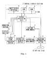
- reference numeral 1 generally denotes the video camera according to the first embodiment of the present invention.
- an optical disc 20 such as a Digital Versatile Disc (DVD)
- DVD Digital Versatile Disc
- a central processing unit 3 of a control circuit section 2 develops and executes various programs stored in advance in ROM 5, which is an Electrical Erasable Programmable Read-Only Memory (EEPROM) such as flash memory, by way of bus 21.
- ROM 5 is an Electrical Erasable Programmable Read-Only Memory (EEPROM) such as flash memory
- EEPROM Electrical Erasable Programmable Read-Only Memory
- the central processing unit 3 comprehensively controls the video camera 1 and executes various processes according to the various programs.
- the central processing unit 3 can update any of the programs stored in the ROM 5 when it is connected to the outside by way of input/output interface 4.
- a camera section (not shown) picks up a moving image of a subject to generate moving image data.
- the moving image data are prepared as video data of a plurality of frames that are temporally successive.
- the central processing unit 3 then generates a moving image stream from the moving image data by compression coding, using a moving image encoder (not shown), typically according to a compression coding system conforming to the Moving Picture Experts Group (MPEG) Standards.
- MPEG Moving Picture Experts Group
- the three picture types include intra-frame coded images referred to as Intra (I) pictures (to be referred to as I frame images hereinafter), inter-frame forwardly predictively coded images referred to as Predictive (P) pictures (to be referred to as P frame images hereinafter) and bidirectionally predictively coded images referred to as Bidirectional (B) pictures (to be referred to as B frame images hereinafter).
- I Intra
- P Predictive
- B Bidirectionally predictively coded images
- four prediction modes are defined by the MPEG Standards. They include an intra-frame coding mode, a forward predictive coding mode, a backward predictive coding mode and a bidirectional predictive coding mode.
- the central processing unit 3 forms Groups of Pictures (GOPs) 50 by grouping a predetermined number of fames of moving images by means of an encoder and assigns the frame image data of each GOP 50 to I frame images, P frame images and B frame images in a predetermined order. Then, the central processing unit 3 processes the frame image data by compression coding according to the assigned picture types.
- GOPs Groups of Pictures
- the central processing unit 3 generates a sound stream by means of the moving image encoder by processing the sound data generated by collecting the surrounding sounds of the subject by means of a microphone (not shown) by a predetermined unit according to the MPEG Standards in parallel with the operation of picking up a moving image of the subject by means of the camera. Still additionally, the central processing unit 3 generates a program stream by time-division multiplexing the moving image stream and the sound stream and sends out the generated program stream to recording/reproduction section 8. Then, the central processing unit 3 records the program stream in the recording region of the optical disc 20 by means of recording/reproduction section 8 as data file.
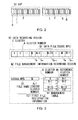
- the optical disc 20 is provided with a data recording region RZ for recording data files DF on the data recording surface and a file management information recording region MZ for recording file management information for managing the data files DF recorded in the data recording region RZ according to the FAT file system.
- the optical disc 20 is also provided with a plurality of clusters C in the data recording region RZ thereof and individually identifiable numbers (to be referred to as cluster numbers hereinafter) A are assigned to the clusters C.
- First file registration information FE1 which is referred to as file entry, can be recorded in the file management information recording region MZ and a management table MT that is referred to as FAT is recorded in the file management information recording region MZ.
- the cluster numbers A that correspond to all the clusters C in the data recording region RZ are listed and described in the management table MT lists, which management table MT is adapted to store the cluster numbers A for indicating the next reference positions (to be referred to as reference cluster numbers Ab hereinafter) in correspondence with the listed cluster numbers A.
- the central processing unit 3 When, for instance, data file DF is recorded over a plurality of clusters C in the data recording region RZ of the optical disc 20, the central processing unit 3 generates file registration information FE1 for registering the data file DF on the basis of the file name B1 of the data file DF recorded in the data recording region RZ. Additionally, the central processing unit 3 detects the cluster number A of the cluster CN recorded in the leading cluster recording part of the data file DF and stores it in the first file registration information FE1 as leading cluster number Aa1 and records the first file registration information FE1 in the file management information recording region MZ by means of the recording/reproduction section 8.
- the central processing unit 3 stores the reference cluster number Ab indicating the next reference position in the cluster C that is being used to record the data file DF by means of the recording/reproduction section 8 in a management table MT. Still additionally, when the cluster C is used to record the rear cluster recording part of the data file DF, the central processing unit 3 stores End Of File (EOF) as numerical value indicating the end of the file.
- EEF End Of File
- the central processing unit 3 reads out the first file registration information FE1 that corresponds to the data file DF in question from the file management information recording region MZ of the optical disc 20 by means of the recording/reproduction section 8. Then, the central processing unit 3 detects the cluster C where each cluster recording part of the data file DF is recorded, sequentially following the cluster numbers A and the reference cluster numbers Ab in the management table MT, on the basis of the leading cluster number Aa1 of the first file registration information FE1 and sequentially reads out the cluster recording parts recorded in the cluster C so as to read out the entire data file DF from the data recording region RZ by means of the recording/reproduction section 8.
- the central processing unit 3 sends out the program stream it reads out to separation/decoding section 10 by means of reproduction work memory 9.
- the separation/decoding section 10 separates the moving image stream and the sound stream from each other out of the program stream. Then, the separation/decoding section 10 decodes the moving image stream by every GOP 50 to generate moving image data and sends out the generated moving image data to output signal processing section 11. Additionally, the separation/decoding section 10 decodes the sound stream by a predetermined unit to generate sound data and sends out the generated sound data to the output signal processing section 11.
- the output signal processing section 11 sends out the moving image data to display section 13 to have it display a moving image according to the moving image data and also the sound data to a speaker (not shown) to output sounds from the speaker according to the sound data in synchronism with the moving image being displayed on the display section 13.
- the central processing unit 3 When the central processing unit 3 is displaying a moving image on the display section 13 and if a file splitting instruction is input from the operation section 12 according to the key operations performed by way of the operation keys to slit the data file DF that corresponds to the moving image being displayed, the central processing unit 3 starts splitting the data file DF recorded in the data recording region RZ into a front side first split data file and a rear side second split data file as viewed from a predetermined file splitting position.
- the central processing unit 3 is sequentially switching a plurality of frames of the moving image so as to consequently display the moving image. Additionally, when the central processing unit 3 reads out the data file DF from the data recording region RZ as program stream, it checks the head information of the GOP 50 in the moving image stream contained in the program stream by time-division multiplexing and detects the frame image data at the front end of the GOP 50 (to be referred to as leading frame image data hereinafter), while it identifies the boundary of the GOPs 50 that are candidates for the file splitting position (to be referred to as GOP boundary hereinafter) from the detected leading frame image data.
- leading frame image data to as leading frame image data
- the central processing unit 3 sequentially detects the cluster numbers A of the clusters C (to be referred to as GOP boundary cluster numbers hereinafter) for recording the cluster recording parts including the GOP boundaries 60 of the data file DF (to be referred to as GOP boundary cluster numbers hereinafter) and sends out the detected GOP boundary cluster numbers to editing work memory 7 to record them there.
- the central processing unit 3 detects the time code added to the frame image data of the frame image that is being displayed when the file splitting instruction is input and compares the time code added to the detected frame image data with the time code of the leading frame image data of each of the GOPs 50 located at the rear side of each of the GOP boundaries 60 included in the respective GOP boundary recording parts corresponding to the plurality of GOP boundary cluster numbers stored in the editing work memory 7. Then, as the central processing unit 3 detects the leading frame image data having the time code closest to the time code of the frame image data, it identifies the GOP boundary cluster number that corresponds to the detected leading frame image data.
- the central processing unit 3 detects the GOP boundary 60 included in the GOP boundary recording part that corresponds to the identified GOP boundary cluster number as the file splitting position D for splitting the data file DF, the GOP boundary recording part that includes the file splitting position D as splitting position cluster recording part R and also the cluster number A that corresponds to the splitting position cluster recording part R as file splitting cluster number AP. Then, the central processing unit 3 reads out the detected file splitting cluster number AP from the editing work memory 7.
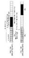
- the central processing unit 3 detects the splitting position cluster recording part R recorded in the cluster C N that corresponds to the file splitting cluster number AP (to be also referred to specifically as file splitting cluster hereinafter) and reads it out from the data recording region RZ. Then, the central processing unit 3 stores the read out splitting position cluster recording part R in the editing work memory 7. Additionally, the central processing unit 3 detects the empty cluster C M that is closest to the file splitting cluster C N from the management table MT. Then, the central processing unit 3 reads out the splitting position cluster recording part R from the editing work memory 7 and records the read out splitting position cluster recording part R in the empty cluster C M by means of the recording/reproduction section 8. In short, the central processing unit 3 copies the splitting position cluster recording part R that includes the file splitting position D recorded in the file splitting cluster C N to the empty cluster C M that is closest to the file splitting cluster C N .
- the central processing unit 3 copies the splitting position cluster recording part R that includes the file splitting position D recorded in the file splitting cluster C N to the empty cluster C M that is closest
- the central processing unit 3 generates second file registration information FE2 for storing the file name B2 for the second split data file that is automatically generated on the basis of the file name B1 of the data file DF. Additionally, the central processing unit 3 detects the cluster number A of the cluster C M for recording the splitting position cluster recording part R after the copying (the leading cluster recording part of the second split data file) and stores it in the second file registration information FE2 as leading cluster number Aa2. Then, the central processing unit 3 records the second file registration information FE2 in the file management information recording region MZ so as to be used for registering the second split data file by means of the recording/reproduction section 8.
- the central processing unit 3 reads out the reference cluster number Ab (which is N+1 in this case) of the cluster number A (which is N in this case) that corresponds to the file splitting cluster C N where the splitting position cluster recording part R before the copying is recorded out of the cluster numbers A listed and stored in the management table MT and copies the cluster number A (which is M in this case) that corresponds to the cluster C M where the splitting position cluster recording part R after the copying is recorded to the reference cluster number Ab.
- the central processing unit 3 alters the reference cluster number Ab of the cluster C M so as to connect the splitting position cluster recording part R before the copying to the cluster recording part next to the splitting position cluster recording part R after the copying.
- the central processing unit 3 uses the first file registration information FE1 used for registering the data file DF before the splitting for the purpose of registering the first split data file. Additionally, the central processing unit 3 rewrites the reference cluster number Ab of the cluster number A that corresponds to the file splitting cluster C N where the splitting position cluster recording part R before the copying is recorded out of the cluster numbers A listed and stored in the management table MT as the EOF showing the numerical value that indicates the end of the file, In other words, the central processing unit 3 alters the reference cluster number A of the file splitting cluster C N so as to bring the splitting position cluster recording part R before the copying to the tail end of the first split data file.
- the central processing unit 3 splits the data file DF recorded in the data recording region RZ into the first split data file where data are recorded in the clusters C s , C s+1 , C s+2 , C s+3 , C s+4 , C s+5 , C s+6 and C N that are identified by tracing the cluster numbers A and the reference cluster numbers Ab of the management table MT in the order of S, S+1, S+2, S+3, S+4, S+5, S+6 and N on the basis of the leading cluster number Aa1 of the file registration information FE1 and the second split data file where data are recorded in the clusters C M , C N+1 , C N+2 , ... that are identified by tracing the cluster numbers A and the reference cluster numbers Ab of the management table MT in the order of M, N+1, N+2, ... on the basis of the leading cluster number Aa2 of the file registration information FE2.
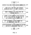
- the central processing unit 3 starts the file splitting process sequence RT1 as shown in FIG. 5.
- the central processing unit 3 detects the file splitting cluster number AP that corresponds to the leading frame image data having the time code closest to the time code added to the frame image data of the frame image that is being displayed when the file splitting instruction is input out of the GOP boundary cluster numbers stored in the editing work memory 7 in Step SP1 and then moves to the next step, or Step SP2.
- Step SP2 the central processing unit 3 copies the splitting position cluster recording part R recorded in the file splitting cluster C N that corresponds to the file splitting cluster number AP to the empty cluster C M and then moves to the next step, or Step SP3.
- Step SP3 the central processing unit 3 generates the second file registration information FE2 for storing the newly generated file name B2 and then moves to the next step, or Step SP4.
- Step SP4 the central processing unit 3 detects the cluster number A of the cluster C M where the splitting position cluster recording part R before the copying is recorded and stores the detected cluster number A in the second file registration information FE2 as leading cluster number Aa2 before it moves to the next step, or Step SP5.
- Step SP5 the central processing unit 3 copies the reference cluster number Ab of the cluster number A that corresponds to the file splitting cluster C N where the splitting position cluster recording part R before the copying is recorded out of the cluster numbers A stored in the management table MT to the reference cluster number Ab of the cluster number A that corresponds to the cluster C M where the splitting position cluster recording part R after the copying is recorded and then moves to the next step, or Step SP6.
- Step SP6 the central processing unit 3 rewrites the reference cluster number Ab of the cluster number A that corresponds to the file splitting cluster C N where the splitting position cluster recording part R before the copying is recorded out of the cluster numbers A stored in the management table MT to EOF and then moves to the next step, or Step SP7, where it ends the file splitting process sequence RT1.
- the video camera 1 splits the data file DF recorded in the data recording region RZ of the optical disc 20 into the first split data file and the second split data file.
- the video camera 1 When a file splitting instruction is input to the video camera 1 having the above-described configuration while a moving image is being displayed, the video camera 1 detects the file splitting cluster number AP for identifying the cluster C that includes the file splitting position D. Then, it also detects the splitting position cluster recording part R recorded in the file splitting cluster C N that corresponds to the file splitting cluster number AP and copies the splitting position cluster recording part R to the empty cluster C M located closest to the file splitting cluster C N .
- the video camera 1 alters the reference cluster number Ab of the cluster C M so as to connect the splitting position cluster recording part R after the copying to the cluster recording part next to the splitting position cluster recording part R before the copying and also alters the reference cluster number Ab of the file splitting cluster C N so as to bring the splitting position cluster recording part R before the copying to the tail end of the first split data file.
- the video camera 1 splits the data file DF recorded in the data recording region RZ of the recording medium at a file splitting position D, it can do so simply by coping the splitting position cluster recording part R that includes the file splitting position D to an empty cluster C M and altering the reference cluster number Ab of the file splitting cluster C N where the splitting position cluster recording part R before the copying is recorded and the reference cluster number Ab of the cluster C M where the splitting position cluster recording part R after the copying is recorded.
- the video camera 1 when the video camera 1 splits the data file DF recorded in the data recording region RZ over a plurality of clusters C at a predetermined file splitting position, it detects the splitting position cluster recording part R that includes the file splitting position D out of the plurality of cluster recording parts of the data file DF recorded over a plurality of clusters C, copies the detected splitting position cluster recording part R to some other cluster C in the data recording region RZ and alters the reference cluster number Ab of the management table MT so as to manage the first split data file and the second split data file obtained by dividing the data file DF at the file splitting position D and also alters the reference cluster number Ab of the management table MT so as to make the splitting position cluster recording part R before the copying and the splitting position cluster recording part R after the copying respectively part of the first split data file and part of the second split data file.
- the video camera 1 splits the data file DF recorded in the data recording region RZ of the recording medium, it can do so simply by coping the splitting position cluster recording part R that includes the file splitting position D to some other cluster C and altering the reference cluster number Ab in the management table MT. Thus, it is possible to simplify the process of splitting a recorded data file.
- the video camera 1 when a data file DF is recorded in the data recording region RZ, the video camera 1 generates first file registration information FE1 for registering the data file DF that is made to correspond to the cluster number A in the management table MT by means of the cluster C where the leading cluster recording part of the data file DF is recorded and, when the data file DF is split at a file splitting position D, the video camera 1 generates second file registration information FE2 for registering the second split data file that is made to correspond to the cluster number A in the management table MT by means of some other cluster C where the splitting position cluster recording part R that includes the file splitting position D is copied, using the first file registration information to register the first split data file.
- first file registration information FE1 for registering the data file DF that is made to correspond to the cluster number A in the management table MT by means of the cluster C where the leading cluster recording part of the data file DF is recorded
- the video camera 1 when the data file DF is split at a file splitting position D, the video camera 1 generates second
- the video camera 1 splits a data file DF into two new files, it is only required to generate information for registering one of the two new files and uses the information for registering the original data file RD as information for registering the other new file so that it is possible to reduce the number of times of writing information in the file management information recording region MZ and hence the number of times of registering new files when splitting a file.
- FIG. 6 shows a video camera 31 according to a second embodiment of the present invention.
- the components same as or similar to those of FIG. 1 are denoted respectively by the same reference symbols.
- the video camera 31 has a configuration same as the above-described first embodiment except a central processing unit 33 arranged in a control circuit section 32.
- the central processing unit 33 When the central processing unit 33 reads out the splitting position cluster recording part R recorded in the cluster C that corresponds to a file splitting cluster number AP at the time of splitting a file, it compares the time code of the splitting position cluster recording part R and the time code of the leading frame image data of the GOP 59 located rearward relative to the GOP boundary 60 of the file splitting position D included in the splitting position cluster recording part R to determine if the leading frame image data of the rear side GOP 50 is located at the head of the splitting position cluster recording part R or not. If it is determined that the leading frame image data is not located at the head of the splitting position cluster recording part R, the central processing unit 33 executes a process same as the one described above for the first embodiment.
- the central processing unit 33 executes a file splitting process of splitting the data file DF at the cluster boundary.
- the central processing unit 33 typically generates file registration information FE3 storing the file name B3 of the second split data file that is automatically generated on the basis of the file name B1 of the data file DF. Additionally, the central processing unit 33 detects the cluster number A of the cluster C where the splitting position cluster recording part R (to be referred to also as split file leading recording part) is recorded as split file leading number and stores it in the file registration information FE3 as leading cluster number Aa3. Then, the central processing unit 33 records the file registration information FE3 in the file management information recording region MZ by means of the recording/reproduction section 8.
- the central processing unit 33 detects the cluster number A of the cluster C where the split file leading recording part is recorded out of the cluster numbers A listed and stored in the management table MT as reference cluster number Ab as the split file tail end number of the first split data file, and replaces the reference cluster number Ab that corresponds to the tail end number of the detected split file with EOF, or the numerical value indicating the end of the file.
- the central processing unit 33 splits a file and the file splitting position D agrees with the a cluster boundary, it splits the data file DF recorded in the data recording region RZ into a first split data file from the leading cluster recording part of the data file DF to the cluster recording part that is recorded in the cluster C corresponding the split file tail end number and a second split data file from the split file leading recording part of the cluster C corresponding the leading cluster number Aa3 of the file registration information FE3 (or the split file leading number) to the cluster recording part at the tail end of the data file DF and ends the file splitting process.
- the central processing unit 33 starts the file splitting process sequence RT2 as shown in FIG. 7, where the components same as those of FIG. 5 are denoted respectively by the same reference symbols.
- the central processing unit 33 starts the file splitting process sequence RT2, it carries out the processing operation of Step SP1 that is same as the corresponding step of the file splitting process sequence RT1 and then moves to Step SP11.
- Step SP11 the central processing unit 33 determines if the leading frame image data of the GOP 50 that is located at the rear side relative to the file splitting position D is at the leading position of the splitting position cluster recording part R or not. If the answer to the question at Step SP11 is negative, it means that the file splitting position D does not agree with the cluster boundary. Therefore, then the central processing unit 33 moves to Step SP2 and sequentially carries out the processing operations of Step SP2 through SP6 and moves to Step SP7 to end the file splitting process sequence RT2 as in the case of the above-described file splitting process sequence RT1 in the first embodiment.
- Step SP11 If, on the other hand, the answer to the question at Step SP11 is affirmative, it means that the file splitting position D agrees with the cluster boundary. Therefore, the central processing unit 33 moves to Step SP12.
- Step SP12 the central processing unit 33 generates file registration information FE3 storing the newly generated file name B3 and moves to the next step, or Step SP13.
- Step SP13 the central processing unit 33 detects the cluster number A of the cluster C where the split file leading recording part is recorded as the split file leading number and stores it in the file registration information FE3 as leading cluster number Aa3 before it moves to the next step, or Step SP14.
- Step SP14 the central processing unit 33 detects the cluster number A stored in the management table MT of the cluster C where the split file leading recording part is recorded as reference number Ab for the split file tail end number and moves to the next step, or Step SP15.
- Step SP15 the central processing unit 33 replaces the reference cluster number Ab that corresponds to the tail end number of the detected split file with EOF, or the numerical value indicating the end of the file and moves to the next step, or Step SP7 and then ends the file splitting process sequence RT2.
- the video camera 31 splits the data file DF recorded in the data recording region RZ of the optical disc 20.
- the video camera 31 executes a file splitting process, it determines if the leading frame image data of the GOP 50 that is found at the rear side relative to the file splitting position D is located at the leading end of the splitting position cluster recording part R or not. If it is determined that the leading frame image data is located at the leading end of the splitting position cluster recording part, the video camera 31 generates file registration information FE3 storing the newly generated file name B3, detects the cluster number A of the cluster C where the split file leading recording part is recorded as split file leading number and stores the detected split file leading number as leading cluster number Aa3. Additionally, the video camera 31 detects the cluster number A stored in the management table MT as reference cluster number Ab of the cluster C where the split file leading recording part is recorded and stores the EOF there, overwriting it as the numerical value indicating the end of the file.
- the video camera 31 splits a data file DF recorded in the data recording region RZ at a file splitting position D, it can split the data file DF simply by altering the reference cluster number Ab in the management table MT without copying the split file leading recording part to some other cluster C when the file splitting position D and the cluster boundary agree with each other.
- the video camera 31 when the video camera 31 splits a data file DF recorded in the data recording region RZ at a file splitting position D, it determines if the file splitting position D is on the cluster boundary or not and, if it is determined that the file splitting position D is on the cluster boundary, the video camera 31 does not copy the splitting position cluster recording part R to some other cluster C. Then, as a result, when the video camera 31 splits a data file DF recorded in the data recording region RZ at a file splitting position D and the file splitting position D and the cluster boundary agree with each other, the video camera 31 is not required to copy the split file leading recording part to some other cluster C and can split the data file DF simply by altering the reference cluster number Ab in the management table MT. In this way, the video camera 31 can accurately execute the file splitting process according to the file splitting position D of the data file DF.
- FIG. 8 shows a video camera 41 according to a third embodiment of the present invention.
- the components same as or similar to those of FIG. 6 are denoted respectively by the same reference symbols.
- the video camera 41 has a configuration same as the above-described second embodiment except a central processing unit 43 arranged in a control circuit section 42.
- the central processing unit 43 When the central processing unit 43 splits a data file DF into a first split data file and a second split data file in a file splitting process, it detects the splitting position cluster recording part R before the copying that is contained at the tail end of the first split data file by means of the recording/reproduction section 8 and overwrites the part of the detected splitting position cluster recording part R located at the rear side of the file splitting position D in the splitting position cluster recording part R with dummy data such as "0".
- the central processing unit 43 when the central processing unit 43 splits the data file DF into a first split data file and a second split data file in a file splitting process, it detects the splitting position cluster recording part R after the copying that is contained at the head of the second split data file by means of the recording/reproduction section 8 and overwrites the part of the detected splitting position cluster recording part R located at the front side of the file splitting position D in the splitting position cluster recording part R.
- the central processing unit 43 starts the file splitting process sequence RT3 as shown in FIG. 9, where the components same as those of FIG. 7 are denoted respectively by the same reference symbols.
- the central processing unit 43 starts the file splitting process sequence RT3, it carries out the processing operations of Steps SP1 through SP6 that are same as the corresponding steps of the above-described file splitting process sequence RT2 in the first embodiment and then moves to Step SP21.
- step SP21 the central processing unit 43 overwrites the part of the splitting position cluster recording part R before the copying located at the rear side of the file splitting position D in the tail end of the first split data file with dummy data and moves to the next step, or Step SP22.
- Step SP22 the central processing unit 43 overwrites the part of the splitting position cluster recording part R after the copying located at the front side of the file splitting position D in the second split data file with dummy data and moves to the next step, or Step SP7, to end the file splitting process sequence RT3.
- the video camera 41 splits the data file DF recorded in the data recording region RZ of the optical disc 20 according to the file splitting process sequence RT3.
- the video camera 41 when the video camera 41 splits a data file DF into a first split data file and a second split data file in the file splitting process, it overwrites the part of the splitting position cluster recording part R before the copying located at the rear side of the file splitting position D and contained at the tail end of the first split data file with dummy data and, at the same time, overwrites the part of the splitting position cluster recording part R after the copying located at the front side of the file splitting position D and contained at the head of the second split data file.
- the first split data file contains the first split program stream obtained by splitting the program stream, which is originally managed as data file DF, at the file splitting position D and also part of the second split program stream.
- the video camera 41 overwrites the part of the splitting position cluster recording part R before the copying that is contained at the tail end of the first split data file and located at the rear side of the file splitting position D with dummy data so that it can delete the part of the second split program stream contained in the first split data file, leaving the first split program stream contained in the first split data file intact.
- the second split data file contains the second split program stream obtained by dividing the program stream, which is originally managed as data file DF, at the file splitting position D and also part of the first split program stream.
- the video camera 41 overwrites the part of the splitting position cluster recording part R after the copying that is contained at the head of the second split data file and located at the front side of the file splitting position D with dummy data so that it can delete the part of the first split program stream contained in the second split data file, leaving the second split program stream contained in the second split data file intact.
- the video camera 41 records the cluster C where the splitting position cluster recording part R before the copying that is now part of first split data file, overwriting the part where the data of the second split data file is left with dummy data, and at the same time records the other cluster C where the splitting position cluster recording part R after the copying that is now part of the second split data file, overwriting the part where the data of the first split data file is left with dummy data.
- the video camera 41 can delete part of the second split program stream contained in the first split data file and also the part of the first split program stream contained in the second split data file so that it can properly reproduce the first split program stream so as to be managed in the first split data file and also the second split program stream so as to be managed in the second split data file when it reproduces the first split data file and the second split data file.
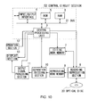
- FIG. 10 shows a video camera 51 according to a fourth embodiment of the present invention.
- the components same as or similar to those of FIG. 8 are denoted respectively by the same reference symbols.
- the video camera 51 has a configuration same as the above-described third embodiment except a central processing unit 53 arranged in a control circuit section 52.
- the central processing unit 53 executes a file splitting process and detects a file splitting cluster number AP, although the file splitting position does not agree with the cluster boundary, it reads out the header of the GOP 50 (to be referred to as GOP header hereinafter) that starts from the file splitting position D and is stored in the cluster C corresponding the file splitting cluster number AP from the data recording region RZ by means of the recording/reproduction section 8.
- GOP header the header of the GOP 50
- self decoding capability identifying information self decoding capability identification flag
- RI self decoding capability identification flag
- the central processing unit 53 determines if the GOP 50 that corresponds to the GOP header it reads out from the data recording region RZ contains a front side reference coded frame image data or not according to if a self decoding capability identification flag RI is set at the GOP header H or not. If a self decoding capability identification flag RI is set at the GOP header H it reads out, the central processing unit 53 determines that the GOP 50 that corresponds to the GOP header H it reads out can decode a plurality of frame images in the GOP 50 by itself and executes a process similar to that of the above-described third embodiment.
- the central processing unit 53 determines that the front side reference coded frame image data is contained and sets a decoding setting flag DI at the GOP header H it reads out.
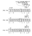
- the central processing unit 53 starts the file splitting process sequence RT4 as shown in FIGS. 11A to 11C, where the components same as those of FIG. 9 are denoted respectively by the same reference symbols.
- the central processing unit 53 starts the file splitting process sequence RT4
- it carries out the processing operation of Step SP1 that is same as the corresponding step of the above-described file splitting process sequence RT3 in the third embodiment and then moves to Step SP31.
- Step SP31 the central processing unit 53 determines if a self decoding capability identification flag RI is set at the GOP header H it reads out from the data recording region RZ or not. If the answer to the question at Step SP31 is affirmative, it means that the GOP 50 that corresponds to the GOP header H it reads out can decode a plurality of frame image data in the GOP 50 by itself. Therefore, the central processing unit 53 then moves to Step SP2 and sequentially carries out the processing operations of Steps SP2 through SP22 that are same as those of the file splitting process sequence RT3 of the above-described third embodiment. Thereafter, the central processing unit 53 moves to Step SP7 to end the file splitting process sequence RT4.
- Step SP31 If, on the other hand, the answer to the question at Step SP31 is negative, it means that the GOP 50 that corresponds to the GOP header H it reads out contains the front side reference coded frame image data. Therefore, the central processing unit 53 then moves to Step SP32.
- Step SP32 the central processing unit 53 sets a decoding setting flag DI at the GOP header H it reads out and moves to the next step, or Step SP7 to end the file splitting process sequence RT4.
- the video camera 51 can split a data file DF recorded in the data recording region RZ of an optical disc 20 by following the file splitting process sequence RT4.
- the video camera 51 when the video camera 51 finds that the file splitting position does not agree with a cluster boundary in a file splitting process and detects a file splitting cluster number AP, it reads out the GOP header H of the GOP 50 that is stored in the cluster C corresponding the file splitting cluster number AP and starts from the file splitting position D from the data recording region RZ and determines if the GOP 50 that corresponds to the GOP header H it reads out contains the front side reference coded frame image data or not according to if a self decoding capability identification flag RI is set at the GOP header H or not. If it is determined that the GOP 50 that corresponds to the GOP header H it reads out contains the front side reference coded frame image data, the video camera 51 sets a decoding setting flag DI at the GOP header it reads out.
- the video camera 51 can decode the entire GOP 50 without problem.
- the video camera 51 when the video camera 51 splits a data file DF recorded in the data recording region RZ at a GOP boundary 60, it determines if the front side reference coded frame image data that needs to be decoded by referring to the coded frame image data in the GOP 50 at the front side relative to the GOP boundary 60 is found in the coded frame image data in the GOP 50 at the rear side relative to the GOP boundary 60 or not and, if the video camera 51 determines that the front side reference coded frame image data is found in the rear side GOP 50, it sets a decoding setting flag DI at the GOP header H of the rear side GOP 50 so that the front side reference coded frame image data may not be decoded.
- the video camera 51 splits a data file DF into a first split data file and a second split data file, it can decode the entire leading GOP 50 of the second split data file without problem if the GOP 50 cannot be decoded completely without referring to the immediately preceding GOP 50.
- the present invention is by no means limited thereto and it may alternatively be so arranged that the splitting position cluster recording part R after the copying is made to be part of the first split data file and the splitting position cluster recording part R before the copying is made to be part of the second split data file.
- the present invention is applied to a data file including program streams formed by compression coding according to MPEG in the case of the first through fourth embodiments described above by referring to FIGS. 1 through 12, the present invention is by no means limited thereto and the present invention can be applied to files that are compression coded according to various kinds of generally used compression coding methods or files not compression coded.
- the present invention is applied to management information for data files according to a FAT file system in the case of the first through fourth embodiments described above by referring to FIGS. 1 through 12, the present invention is by no means limited thereto and the present invention can be applied to other management information in various different ways unless part of a data file can be managed as part of some other data file according to such management information.
- the present invention is by no means limited thereto and the tail end of a GOP 50 may alternatively be detected. Still alternatively, it may be so arranged as to detect the head or the tail end of packet data or some other unit of data.
- While the present invention is applied to an optical disc as recording medium for recording data files in the first through fourth embodiments described above by referring to FIGS. 1 through 12, the present invention is by no means limited thereto and the present invention can also be applied to various other storage mediums such that can record data files such as Compact Discs (CDs) and other types of optical discs, semiconductor memories, Hard Disk Drives (HDDs) and FLOPPY (Registered Trademark) Disks(FDs).
- CDs Compact Discs
- HDDs Hard Disk Drives
- FLOPPY Registered Trademark
- the present invention is applied to video cameras 1, 31, 41 and 51 as file splitting apparatus according to the invention in the first through fourth embodiments described above by referring to FIGS. 1 through 12, the present invention is by no means limited thereto and the present invention can also be applied to file splitting apparatus of various other types such as Hard Disk (HD) recorders, HD video cameras and personal computers.
- HD Hard Disk
- central processing units 3, 33, 43, 53 are applied as management region recording part detecting section for detecting a management region recording part that includes a file splitting position out of a plurality of management region recording parts recorded in a plurality of recording management regions of a data file recorded in a recording region when splitting the data file at a predetermined file splitting position in the above description of the first through fourth embodiments given above by referring to FIGS.
- the present invention is by no means limited thereto and a management region recording part detecting circuit that is formed as hardware or some other management region recording part detecting section may alternatively be applied to detect a management region recording part that includes a file splitting position out of a plurality of management region recording parts recorded in a plurality of recording management regions of a data file recorded in a recording region when splitting the data file at a predetermined file splitting position.
- the central processing units 3, 33, 43, 53 are applied as management region recording part copying section for copying the management region recording part including the file splitting position detected by the management region recording part detecting section to some other recording management region of the recording region in the above description of the first through fourth embodiments given above by referring to FIGS.
- the present invention is by no means limited thereto and a management region recording part copying circuit that is formed as hardware or some other management region recording part copying section may alternatively be applied to copy the management region recording part that includes the file splitting position to some other recording management region of the recording region.
- central processing units 3, 33, 43, 53 are applied as management information altering section for altering the management information of a data file to first management information for managing one of the split data files obtained by splitting the data file at a file splitting position and second management information for managing the other split data file in the description of the first through fourth embodiments given above by referring FIGS. 1 through 12, the present invention is by no means limited thereto and a management information altering circuit that is formed as hardware or some other management information altering section may alternatively be applied to alter the management information of a data file to first management information for managing one of the split data files obtained by splitting the data file at a file splitting position and second management information for managing the other split data file.
- the central processing units 3, 33, 43, 53 are applied as splitting position determining section for determining if a file splitting position agrees with the boundary of adjacent recording management regions or not when splitting a data file recorded in the recording region at the boundary of two consecutive unit image groups as file splitting position in the above description of the second through fourth embodiments given above by referring to FIGS. 1 through 12, the present invention is by no means limited thereto and a splitting position determining circuit that is formed as hardware or some other splitting position determining section may alternatively be applied to determine if a file splitting position is located at the boundary of two adjacent recording management regions or not when splitting a data file recorded in the recording region at the boundary of two consecutive unit image groups as file splitting position.
- central processing unit 3, 33, 43, 53 are applied as registration information generating section for generating first file registration information for registering a data file that is made to correspond to the management information in the recording management region where the leading management region recording part of the data file is recorded when the data file is recorded in the recording region and generating second file registration information for registering one of the split data files that is made to correspond to the second management information in one of the recording management regions where the management region recording part including a file splitting position is copied by using the first file registration information to register the other split data file or generating second file registration information for registering the other split data file that is made to correspond to the first management information in the other recording management region where the management region recording part including the file splitting position is recorded by using the first file registration information to register the former split data file when the data file is split at the file splitting position in the above description of the first through fourth embodiments given above by referring to FIGS.
- the present invention is by no means limited thereto and a registration information generating circuit that is formed as hardware or some other registration information generating section may alternatively be applied to generate first file registration information for registering a data file that is made to correspond to the management information in the recording management region where the leading management region recording part of the data file is recorded when the data file is recorded in the recording region and generate second file registration information for registering one of the split data files that is made to correspond to the second management information in one of the recording management regions where the management region recording part including a file splitting position is copied by using the first file registration information to register the other split data file or generate second file registration information for registering the other split data file that is made to correspond to the first management information in the other recording management region where the management region recording part including the file splitting position is recorded by using the first file registration information to register the former split data file when the data file is split at the file splitting position.
- a registration information generating circuit that is formed as hardware or some other registration information generating section may alternatively be applied to generate first file registration information for registering registering
- the recording/reproduction section 8 described above by referring to FIGS. 1 through 12 is applied as recording section for recording program streams that is put into a group, or a GOP, as a predetermined unit of coded frame image data of a plurality of consecutive coded frame image data to be recorded as data file, the coded frame image data being generated from moving image data formed by a plurality of consecutive frame image data by compression coding by means of a compression coding system conforming to the MPEG Standards, in the above description of the fourth embodiment, the present invention is by no means limited thereto and any other recording section such as Hard Disk (HD) recorders, HD video cameras and personal computers may alternatively applied for the purpose of the present invention.
- HD Hard Disk
- the central processing units 3, 33, 43, 53 described above by referring to FIGS. 1 through 12 are applied as determining section for determining if the front side reference coded frame image data that is to be decoded by referring to the coded frame image data in the front side GOP relative to the boundary is found in the coded frame image data in the rear side GOP relative to a boundary when a data file that is recorded in the recording region is split at a file splitting position on the boundary of two consecutive GOPs in the above description of the fourth embodiment
- the present invention is by no means limited thereto and a determining circuit that is formed as hardware or some other determining section may alternatively be applied to determine if the front side reference coded frame image data that is to be decoded by referring to the coded frame image data in the front side GOP relative to the boundary is found in the coded frame image data in the rear side GOP relative to a boundary when a data file that is recorded in the recording region is split at a file splitting position on the boundary of two consecutive GOPs.
- the central processing units 3, 33, 43 53 described above by referring to FIGS. 1 through 12 are applied as setting section for setting the rear side GOP so as not to decode the front side reference coded frame image data when it is determined by the determining section that the front side reference coded frame image data is found in the rear side GOP in the above description of the fourth embodiment
- the present invention is by no means limited thereto and a setting circuit that is formed as hardware or some other setting section may alternatively be applied to set the rear side GOP so as not to decode the front side reference coded frame image data when it is determined by the determining section that the front side reference coded frame image data is found in the rear side GOP.
- the present invention can find applications in the field of file splitting apparatus such as video cameras adapted to execute a splitting process for splitting a recorded file.
Landscapes
- Engineering & Computer Science (AREA)
- Multimedia (AREA)
- Signal Processing (AREA)
- Television Signal Processing For Recording (AREA)
- Signal Processing For Digital Recording And Reproducing (AREA)
- Management Or Editing Of Information On Record Carriers (AREA)
Applications Claiming Priority (1)
| Application Number | Priority Date | Filing Date | Title |
|---|---|---|---|
| JP2006182210A JP2008010110A (ja) | 2006-06-30 | 2006-06-30 | ファイル分割装置、ファイル分割方法及びファイル分割プログラム |
Publications (2)
| Publication Number | Publication Date |
|---|---|
| EP1892716A1 true EP1892716A1 (de) | 2008-02-27 |
| EP1892716B1 EP1892716B1 (de) | 2009-04-15 |
Family
ID=38790149
Family Applications (1)
| Application Number | Title | Priority Date | Filing Date |
|---|---|---|---|
| EP20070110762 Not-in-force EP1892716B1 (de) | 2006-06-30 | 2007-06-21 | Dateiteilung durch Teilung der Cluster und der Management Information |
Country Status (7)
| Country | Link |
|---|---|
| US (1) | US7716259B2 (de) |
| EP (1) | EP1892716B1 (de) |
| JP (1) | JP2008010110A (de) |
| KR (1) | KR20080003262A (de) |
| CN (1) | CN101097760B (de) |
| DE (1) | DE602007000901D1 (de) |
| TW (1) | TWI349929B (de) |
Families Citing this family (11)
| Publication number | Priority date | Publication date | Assignee | Title |
|---|---|---|---|---|
| JP5035596B2 (ja) * | 2006-09-19 | 2012-09-26 | ソニー株式会社 | 情報処理装置および方法、並びにプログラム |
| JP4779921B2 (ja) * | 2006-10-05 | 2011-09-28 | ソニー株式会社 | データ処理装置及びデータ処理方法、並びにコンピュータ・プログラム |
| US8898563B2 (en) * | 2007-04-13 | 2014-11-25 | Gvbb Holdings S.A.R.L. | Editing apparatus and an editing method |
| CN101755461B (zh) * | 2007-07-20 | 2012-06-13 | 富士胶片株式会社 | 图像处理设备、图像处理方法 |
| JP2009182458A (ja) * | 2008-01-29 | 2009-08-13 | Sony Corp | 通信装置、通信システム、通信方法及びプログラム |
| JP5024351B2 (ja) * | 2008-11-28 | 2012-09-12 | 株式会社ニコン | 画像ファイル生成装置、カメラ、および画像ファイル生成プログラム |
| CA2673554C (en) * | 2009-07-21 | 2017-01-03 | Ibm Canada Limited - Ibm Canada Limitee | Web distributed storage system |
| CN102622340B (zh) * | 2012-03-28 | 2014-03-19 | 成都优译信息技术有限公司 | 翻译文件的拆分和分配方法 |
| US9979959B2 (en) * | 2012-04-20 | 2018-05-22 | Qualcomm Incorporated | Video coding with enhanced support for stream adaptation and splicing |
| CN106294683A (zh) * | 2016-08-05 | 2017-01-04 | 中国银行股份有限公司 | 一种文件拆分方法及装置 |
| CN116305301B (zh) * | 2023-05-26 | 2023-07-28 | 南昌工程学院 | 人员电子档案数据保护方法及系统 |
Citations (3)
| Publication number | Priority date | Publication date | Assignee | Title |
|---|---|---|---|---|
| EP1020862A2 (de) * | 1997-09-17 | 2000-07-19 | Matsushita Electric Industrial Co., Ltd. | Optische Platte, Videodatenschnittgerät, rechnerlesbares Aufzeichnungsmedium das ein Schnittprogramm speichert, Wiedergabegerät für die optische Platte und rechnerlesbares Aufzeichnungsmedium das ein Wiedergabeprogramm speichert |
| US6219043B1 (en) * | 1995-07-13 | 2001-04-17 | Kabushiki Kaisha Toshiba | Method and system to replace sections of an encoded video bitstream |
| US20050089312A1 (en) * | 1994-10-11 | 2005-04-28 | Mitsubishi Denki Kabushiki Kaisha | Disk media, and method of and device for recording and playing back information on or from a disk media |
Family Cites Families (12)
| Publication number | Priority date | Publication date | Assignee | Title |
|---|---|---|---|---|
| JPH08149408A (ja) * | 1994-11-17 | 1996-06-07 | Matsushita Electric Ind Co Ltd | ディジタル動画編集方法及び装置 |
| JPH11176083A (ja) * | 1997-12-12 | 1999-07-02 | Hitachi Ltd | 画像音声記録再生装置 |
| JP2001228895A (ja) * | 2000-02-18 | 2001-08-24 | Nippon Columbia Co Ltd | オーディオデータ記憶装置およびオーディオデータ記憶方法 |
| JP3976979B2 (ja) * | 2000-02-21 | 2007-09-19 | シャープ株式会社 | 画像編集装置 |
| US6725343B2 (en) * | 2000-10-05 | 2004-04-20 | Hewlett-Packard Development Company, L.P. | System and method for generating cache coherence directory entries and error correction codes in a multiprocessor system |
| JP2003272359A (ja) * | 2002-03-15 | 2003-09-26 | Canon Inc | 映像データの編集方法 |
| JP3855862B2 (ja) | 2002-04-01 | 2006-12-13 | ソニー株式会社 | 編集方法および装置 |
| JP3880491B2 (ja) * | 2002-09-17 | 2007-02-14 | キヤノン株式会社 | データ編集方法 |
| JP2005005895A (ja) * | 2003-06-10 | 2005-01-06 | Canon Inc | データ編集方法及び装置 |
| JP2005032745A (ja) | 2003-07-07 | 2005-02-03 | Hitachi Metals Ltd | 焼結フェライト磁石およびその製造方法 |
| JP4464101B2 (ja) * | 2003-10-10 | 2010-05-19 | キヤノン株式会社 | トランスポートストリーム編集方法及び装置 |
| EP1596396A1 (de) * | 2004-05-15 | 2005-11-16 | Deutsche Thomson-Brandt Gmbh | Verfahren zum Teilen eines Datenstroms |
-
2006
- 2006-06-30 JP JP2006182210A patent/JP2008010110A/ja active Pending
-
2007
- 2007-04-18 US US11/736,787 patent/US7716259B2/en not_active Expired - Fee Related
- 2007-04-24 TW TW096114460A patent/TWI349929B/zh not_active IP Right Cessation
- 2007-06-04 CN CN2007101082013A patent/CN101097760B/zh not_active Expired - Fee Related
- 2007-06-21 DE DE200760000901 patent/DE602007000901D1/de active Active
- 2007-06-21 EP EP20070110762 patent/EP1892716B1/de not_active Not-in-force
- 2007-06-27 KR KR20070063904A patent/KR20080003262A/ko not_active Withdrawn
Patent Citations (3)
| Publication number | Priority date | Publication date | Assignee | Title |
|---|---|---|---|---|
| US20050089312A1 (en) * | 1994-10-11 | 2005-04-28 | Mitsubishi Denki Kabushiki Kaisha | Disk media, and method of and device for recording and playing back information on or from a disk media |
| US6219043B1 (en) * | 1995-07-13 | 2001-04-17 | Kabushiki Kaisha Toshiba | Method and system to replace sections of an encoded video bitstream |
| EP1020862A2 (de) * | 1997-09-17 | 2000-07-19 | Matsushita Electric Industrial Co., Ltd. | Optische Platte, Videodatenschnittgerät, rechnerlesbares Aufzeichnungsmedium das ein Schnittprogramm speichert, Wiedergabegerät für die optische Platte und rechnerlesbares Aufzeichnungsmedium das ein Wiedergabeprogramm speichert |
Also Published As
| Publication number | Publication date |
|---|---|
| TW200822079A (en) | 2008-05-16 |
| US20080046614A1 (en) | 2008-02-21 |
| CN101097760A (zh) | 2008-01-02 |
| CN101097760B (zh) | 2010-06-16 |
| KR20080003262A (ko) | 2008-01-07 |
| DE602007000901D1 (de) | 2009-05-28 |
| TWI349929B (en) | 2011-10-01 |
| US7716259B2 (en) | 2010-05-11 |
| JP2008010110A (ja) | 2008-01-17 |
| EP1892716B1 (de) | 2009-04-15 |
Similar Documents
| Publication | Publication Date | Title |
|---|---|---|
| EP1892716B1 (de) | Dateiteilung durch Teilung der Cluster und der Management Information | |
| JP5332773B2 (ja) | 画像処理装置および方法 | |
| EP1818937A1 (de) | Aufzeichnungsgerät, Aufzeichnungsverfahren, Programm für das Aufzeichnungsverfahren, Aufzeichnungsmedium zur Aufzeichnung des Programms für das Aufzeichnungsverfahren, Wiedergabegerät, Wiedergabeverfahren, Programm für das Wiedergabeverfahren und Aufzeichnungsmedium zur Aufzeichnung des Programms für das Wiedergabeverfahren | |
| JP2010022003A (ja) | 動画ファイル再生装置、動画ファイル再生方法、プログラム | |
| JP4251219B2 (ja) | 編集装置及び編集方法 | |
| CN102263987A (zh) | 图像处理设备及其控制方法 | |
| JP3835554B2 (ja) | ファイル記録装置、ファイル再生装置、ファイル記録方法、ファイル記録方法のプログラム、ファイル記録方法のプログラムを記録した記録媒体、ファイル再生方法、ファイル再生方法のプログラム及びファイル再生方法のプログラムを記録した記録媒体 | |
| JP2005005810A (ja) | メディアデータ管理方法、ディスク録画装置、ディスク再生装置、メディアデータ管理システム、コンピュータプログラム及びコンピュータ読み取り可能な記録媒体 | |
| CN1578443A (zh) | 动图像记录设备及其方法 | |
| JP4552802B2 (ja) | 記録装置、記録方法、記録方法のプログラム及び記録方法のプログラムを記録した記録媒体 | |
| JP2001043616A (ja) | 記録方法、記録媒体及び記録装置 | |
| WO2006052100A1 (en) | Method and apparatus for writing information on picture data sections in a data stream and for using the information | |
| JP4464101B2 (ja) | トランスポートストリーム編集方法及び装置 | |
| KR101049747B1 (ko) | 실시간 디지털 정보신호 스트림을 저장하는 장치 및 방법 | |
| JP2002373480A (ja) | データ記録方法及びデータ記録装置ならびに記録媒体 | |
| JP4772742B2 (ja) | 画像再生装置、画像再生方法及びプログラム記録媒体 | |
| JP4788607B2 (ja) | 撮像装置、画像処理装置、画像処理方法、画像処理方法のプログラム及び画像処理方法のプログラムを記録した記録媒体 | |
| JP2006325086A5 (de) | ||
| JP4197163B2 (ja) | データ処理装置 | |
| JP4289403B2 (ja) | 編集装置及び編集方法 | |
| CN100438604C (zh) | 数字内容分割装置、数字内容重放装置和数字内容分割方法 | |
| JP2008262610A (ja) | 情報処理装置および情報処理方法、プログラム格納媒体、並びにプログラム | |
| JP4660435B2 (ja) | データ処理装置 | |
| JP4654161B2 (ja) | 記録装置及び記録方法 | |
| JP4208022B2 (ja) | 情報編集装置、情報編集方法及びプログラム記録媒体 |
Legal Events
| Date | Code | Title | Description |
|---|---|---|---|
| PUAI | Public reference made under article 153(3) epc to a published international application that has entered the european phase |
Free format text: ORIGINAL CODE: 0009012 |
|
| AK | Designated contracting states |
Kind code of ref document: A1 Designated state(s): AT BE BG CH CY CZ DE DK EE ES FI FR GB GR HU IE IS IT LI LT LU LV MC MT NL PL PT RO SE SI SK TR |
|
| AX | Request for extension of the european patent |
Extension state: AL BA HR MK YU |
|
| 17P | Request for examination filed |
Effective date: 20080326 |
|
| 17Q | First examination report despatched |
Effective date: 20080502 |
|
| AKX | Designation fees paid |
Designated state(s): DE FR GB |
|
| RTI1 | Title (correction) |
Free format text: FILE SPLITTING BY SPLITTING CLUSTERS AND MANAGEMENT INFORMATION |
|
| GRAP | Despatch of communication of intention to grant a patent |
Free format text: ORIGINAL CODE: EPIDOSNIGR1 |
|
| GRAS | Grant fee paid |
Free format text: ORIGINAL CODE: EPIDOSNIGR3 |
|
| GRAA | (expected) grant |
Free format text: ORIGINAL CODE: 0009210 |
|
| AK | Designated contracting states |
Kind code of ref document: B1 Designated state(s): DE FR GB |
|
| REG | Reference to a national code |
Ref country code: GB Ref legal event code: FG4D |
|
| REF | Corresponds to: |
Ref document number: 602007000901 Country of ref document: DE Date of ref document: 20090528 Kind code of ref document: P |
|
| PLBE | No opposition filed within time limit |
Free format text: ORIGINAL CODE: 0009261 |
|
| STAA | Information on the status of an ep patent application or granted ep patent |
Free format text: STATUS: NO OPPOSITION FILED WITHIN TIME LIMIT |
|
| 26N | No opposition filed |
Effective date: 20100118 |
|
| REG | Reference to a national code |
Ref country code: GB Ref legal event code: 746 Effective date: 20120702 |
|
| REG | Reference to a national code |
Ref country code: DE Ref legal event code: R084 Ref document number: 602007000901 Country of ref document: DE Effective date: 20120614 |
|
| PGFP | Annual fee paid to national office [announced via postgrant information from national office to epo] |
Ref country code: GB Payment date: 20120622 Year of fee payment: 6 Ref country code: FR Payment date: 20120705 Year of fee payment: 6 |
|
| PGFP | Annual fee paid to national office [announced via postgrant information from national office to epo] |
Ref country code: DE Payment date: 20120822 Year of fee payment: 6 |
|
| GBPC | Gb: european patent ceased through non-payment of renewal fee |
Effective date: 20130621 |
|
| REG | Reference to a national code |
Ref country code: DE Ref legal event code: R119 Ref document number: 602007000901 Country of ref document: DE Effective date: 20140101 |
|
| REG | Reference to a national code |
Ref country code: FR Ref legal event code: ST Effective date: 20140228 |
|
| PG25 | Lapsed in a contracting state [announced via postgrant information from national office to epo] |
Ref country code: DE Free format text: LAPSE BECAUSE OF NON-PAYMENT OF DUE FEES Effective date: 20140101 Ref country code: GB Free format text: LAPSE BECAUSE OF NON-PAYMENT OF DUE FEES Effective date: 20130621 |
|
| PG25 | Lapsed in a contracting state [announced via postgrant information from national office to epo] |
Ref country code: FR Free format text: LAPSE BECAUSE OF NON-PAYMENT OF DUE FEES Effective date: 20130701 |