EP1892748B1 - Système de traitement de matériau et procédé de traitement de matériau - Google Patents
Système de traitement de matériau et procédé de traitement de matériau Download PDFInfo
- Publication number
- EP1892748B1 EP1892748B1 EP07022228A EP07022228A EP1892748B1 EP 1892748 B1 EP1892748 B1 EP 1892748B1 EP 07022228 A EP07022228 A EP 07022228A EP 07022228 A EP07022228 A EP 07022228A EP 1892748 B1 EP1892748 B1 EP 1892748B1
- Authority
- EP
- European Patent Office
- Prior art keywords
- work piece
- gas
- electron
- processing system
- object plane
- Prior art date
- Legal status (The legal status is an assumption and is not a legal conclusion. Google has not performed a legal analysis and makes no representation as to the accuracy of the status listed.)
- Expired - Lifetime
Links
- 238000012545 processing Methods 0.000 title claims description 131
- 239000000463 material Substances 0.000 title claims description 88
- 238000003672 processing method Methods 0.000 title description 4
- 238000010894 electron beam technology Methods 0.000 claims description 45
- 238000006243 chemical reaction Methods 0.000 claims description 40
- 238000000034 method Methods 0.000 claims description 24
- 238000007789 sealing Methods 0.000 claims description 16
- 230000008569 process Effects 0.000 claims description 11
- 238000005086 pumping Methods 0.000 claims description 7
- 230000003993 interaction Effects 0.000 claims description 2
- 239000007789 gas Substances 0.000 description 180
- 239000012495 reaction gas Substances 0.000 description 63
- 239000007858 starting material Substances 0.000 description 43
- MHAJPDPJQMAIIY-UHFFFAOYSA-N Hydrogen peroxide Chemical compound OO MHAJPDPJQMAIIY-UHFFFAOYSA-N 0.000 description 12
- 230000007547 defect Effects 0.000 description 12
- 241001631457 Cannula Species 0.000 description 8
- 230000008439 repair process Effects 0.000 description 8
- 238000005496 tempering Methods 0.000 description 7
- 239000007787 solid Substances 0.000 description 6
- 238000004804 winding Methods 0.000 description 6
- 244000089486 Phragmites australis subsp australis Species 0.000 description 5
- 238000001816 cooling Methods 0.000 description 5
- 238000000151 deposition Methods 0.000 description 5
- 230000008021 deposition Effects 0.000 description 5
- 238000001704 evaporation Methods 0.000 description 5
- 238000010884 ion-beam technique Methods 0.000 description 5
- 238000000926 separation method Methods 0.000 description 5
- 238000006073 displacement reaction Methods 0.000 description 4
- 230000008020 evaporation Effects 0.000 description 4
- 239000012530 fluid Substances 0.000 description 4
- 150000002500 ions Chemical class 0.000 description 4
- 239000007788 liquid Substances 0.000 description 4
- 238000003754 machining Methods 0.000 description 4
- 230000003287 optical effect Effects 0.000 description 4
- 239000000758 substrate Substances 0.000 description 4
- YGBYJRVGNBVTCQ-UHFFFAOYSA-N C[Pt](C)C.[CH]1C=CC=C1 Chemical compound C[Pt](C)C.[CH]1C=CC=C1 YGBYJRVGNBVTCQ-UHFFFAOYSA-N 0.000 description 3
- 230000008859 change Effects 0.000 description 3
- 238000001514 detection method Methods 0.000 description 3
- 238000002149 energy-dispersive X-ray emission spectroscopy Methods 0.000 description 3
- 238000003384 imaging method Methods 0.000 description 3
- 239000002245 particle Substances 0.000 description 3
- 239000004065 semiconductor Substances 0.000 description 3
- 125000006850 spacer group Chemical group 0.000 description 3
- VYPSYNLAJGMNEJ-UHFFFAOYSA-N Silicium dioxide Chemical compound O=[Si]=O VYPSYNLAJGMNEJ-UHFFFAOYSA-N 0.000 description 2
- DSVGQVZAZSZEEX-UHFFFAOYSA-N [C].[Pt] Chemical compound [C].[Pt] DSVGQVZAZSZEEX-UHFFFAOYSA-N 0.000 description 2
- TZCXTZWJZNENPQ-UHFFFAOYSA-L barium sulfate Chemical compound [Ba+2].[O-]S([O-])(=O)=O TZCXTZWJZNENPQ-UHFFFAOYSA-L 0.000 description 2
- 230000008901 benefit Effects 0.000 description 2
- 238000005229 chemical vapour deposition Methods 0.000 description 2
- 239000002131 composite material Substances 0.000 description 2
- 230000001419 dependent effect Effects 0.000 description 2
- 230000000694 effects Effects 0.000 description 2
- 229920001971 elastomer Polymers 0.000 description 2
- 239000000806 elastomer Substances 0.000 description 2
- 238000000635 electron micrograph Methods 0.000 description 2
- 238000005530 etching Methods 0.000 description 2
- 238000010438 heat treatment Methods 0.000 description 2
- 238000002513 implantation Methods 0.000 description 2
- 239000002244 precipitate Substances 0.000 description 2
- 239000002243 precursor Substances 0.000 description 2
- 230000005855 radiation Effects 0.000 description 2
- 230000009467 reduction Effects 0.000 description 2
- 230000004044 response Effects 0.000 description 2
- 238000000859 sublimation Methods 0.000 description 2
- 230000008022 sublimation Effects 0.000 description 2
- 238000012546 transfer Methods 0.000 description 2
- 230000007704 transition Effects 0.000 description 2
- 230000001960 triggered effect Effects 0.000 description 2
- 238000003466 welding Methods 0.000 description 2
- 206010001488 Aggression Diseases 0.000 description 1
- VYZAMTAEIAYCRO-UHFFFAOYSA-N Chromium Chemical compound [Cr] VYZAMTAEIAYCRO-UHFFFAOYSA-N 0.000 description 1
- 229920002449 FKM Polymers 0.000 description 1
- 101000873785 Homo sapiens mRNA-decapping enzyme 1A Proteins 0.000 description 1
- 229910004298 SiO 2 Inorganic materials 0.000 description 1
- 230000001133 acceleration Effects 0.000 description 1
- 230000003213 activating effect Effects 0.000 description 1
- 230000002411 adverse Effects 0.000 description 1
- 230000000903 blocking effect Effects 0.000 description 1
- 238000012512 characterization method Methods 0.000 description 1
- 239000007795 chemical reaction product Substances 0.000 description 1
- 229910052804 chromium Inorganic materials 0.000 description 1
- 239000011651 chromium Substances 0.000 description 1
- 238000004891 communication Methods 0.000 description 1
- 150000001875 compounds Chemical class 0.000 description 1
- 239000000110 cooling liquid Substances 0.000 description 1
- 238000012937 correction Methods 0.000 description 1
- 230000002950 deficient Effects 0.000 description 1
- 230000004069 differentiation Effects 0.000 description 1
- 238000007599 discharging Methods 0.000 description 1
- 230000005684 electric field Effects 0.000 description 1
- 238000007786 electrostatic charging Methods 0.000 description 1
- 238000000921 elemental analysis Methods 0.000 description 1
- 230000005284 excitation Effects 0.000 description 1
- 239000011521 glass Substances 0.000 description 1
- 239000011261 inert gas Substances 0.000 description 1
- 230000000977 initiatory effect Effects 0.000 description 1
- 238000002347 injection Methods 0.000 description 1
- 239000007924 injection Substances 0.000 description 1
- 238000001459 lithography Methods 0.000 description 1
- 102100035856 mRNA-decapping enzyme 1A Human genes 0.000 description 1
- 238000004519 manufacturing process Methods 0.000 description 1
- 239000000203 mixture Substances 0.000 description 1
- 238000012634 optical imaging Methods 0.000 description 1
- 230000010363 phase shift Effects 0.000 description 1
- 230000000979 retarding effect Effects 0.000 description 1
- 235000012239 silicon dioxide Nutrition 0.000 description 1
- 239000000377 silicon dioxide Substances 0.000 description 1
- 239000000243 solution Substances 0.000 description 1
- 238000001228 spectrum Methods 0.000 description 1
- REWDXIKKFOQRID-UHFFFAOYSA-N tetrabutylsilane Chemical compound CCCC[Si](CCCC)(CCCC)CCCC REWDXIKKFOQRID-UHFFFAOYSA-N 0.000 description 1
Images


Classifications
-
- H—ELECTRICITY
- H01—ELECTRIC ELEMENTS
- H01J—ELECTRIC DISCHARGE TUBES OR DISCHARGE LAMPS
- H01J37/00—Discharge tubes with provision for introducing objects or material to be exposed to the discharge, e.g. for the purpose of examination or processing thereof
- H01J37/02—Details
- H01J37/18—Vacuum locks ; Means for obtaining or maintaining the desired pressure within the vessel
-
- H—ELECTRICITY
- H01—ELECTRIC ELEMENTS
- H01J—ELECTRIC DISCHARGE TUBES OR DISCHARGE LAMPS
- H01J37/00—Discharge tubes with provision for introducing objects or material to be exposed to the discharge, e.g. for the purpose of examination or processing thereof
- H01J37/30—Electron-beam or ion-beam tubes for localised treatment of objects
- H01J37/305—Electron-beam or ion-beam tubes for localised treatment of objects for casting, melting, evaporating, or etching
- H01J37/3053—Electron-beam or ion-beam tubes for localised treatment of objects for casting, melting, evaporating, or etching for evaporating or etching
- H01J37/3056—Electron-beam or ion-beam tubes for localised treatment of objects for casting, melting, evaporating, or etching for evaporating or etching for microworking, e. g. etching of gratings or trimming of electrical components
-
- H—ELECTRICITY
- H01—ELECTRIC ELEMENTS
- H01J—ELECTRIC DISCHARGE TUBES OR DISCHARGE LAMPS
- H01J2237/00—Discharge tubes exposing object to beam, e.g. for analysis treatment, etching, imaging
- H01J2237/006—Details of gas supplies, e.g. in an ion source, to a beam line, to a specimen or to a workpiece
-
- H—ELECTRICITY
- H01—ELECTRIC ELEMENTS
- H01J—ELECTRIC DISCHARGE TUBES OR DISCHARGE LAMPS
- H01J2237/00—Discharge tubes exposing object to beam, e.g. for analysis treatment, etching, imaging
- H01J2237/16—Vessels
- H01J2237/162—Open vessel, i.e. one end sealed by object or workpiece
-
- H—ELECTRICITY
- H01—ELECTRIC ELEMENTS
- H01J—ELECTRIC DISCHARGE TUBES OR DISCHARGE LAMPS
- H01J2237/00—Discharge tubes exposing object to beam, e.g. for analysis treatment, etching, imaging
- H01J2237/16—Vessels
- H01J2237/166—Sealing means
-
- H—ELECTRICITY
- H01—ELECTRIC ELEMENTS
- H01J—ELECTRIC DISCHARGE TUBES OR DISCHARGE LAMPS
- H01J2237/00—Discharge tubes exposing object to beam, e.g. for analysis treatment, etching, imaging
- H01J2237/30—Electron or ion beam tubes for processing objects
- H01J2237/317—Processing objects on a microscale
- H01J2237/3174—Etching microareas
- H01J2237/31742—Etching microareas for repairing masks
- H01J2237/31744—Etching microareas for repairing masks introducing gas in vicinity of workpiece
Definitions
- the invention relates to a material processing system and a material processing method, which can be used in particular in processes for material processing by material separation from gases, such as CVD (Chemical Vapor Deposition), or material removal with the supply of reaction gases.
- gas reaction which leads to a material separation or to a material removal, triggered by an energy beam, which is directed to a region of the workpiece to be machined.
- Such a conventional system is out US 5,055,696 known.
- a plurality of reaction gases are optionally introduced into a processing chamber in which the workpiece to be processed is arranged, and the reaction of the reaction gases with the workpiece is triggered by a focused ion beam or photon beam.
- the machined workpieces include integrated circuits and photomasks for integrated circuit fabrication.
- US 5,148,024 discloses an ion beam processing apparatus and associated gas gun
- US 5,435,850 discloses a gas injection system.
- EP 0 106 510 discloses a processing apparatus, such as for a semiconductor wafer, having a device for generating a localized vacuum.
- the apparatus comprises a gas feed for supplying inert gas to the impingement area of the charged particle beam.
- Embodiments of the invention use a gas delivery assembly having at least one gas supply for supplying a reaction gas to a reaction site in a material processing system.
- the reaction gas comprises in particular a so-called "precursor gas” which can be activated in the vicinity of the reaction site by an energy beam in order to lead to material deposition at the reaction site on the workpiece to be machined or to material removal on the workpiece.
- the supply of the reaction gas is to control targeted, i. a flow of the reaction gas must be connectable and can be switched off.
- the gas supply comprises a tube having a first inner cross section, in which a valve body for controlling the gas flow between a first position in which it releases the gas flow, and a second position in which it substantially obstructs the gas flow, and is displaced back and forth ,
- a thinner compared to the tube cannula is coupled to transport the reaction gas to near the reaction site.
- a volume of a continuous gas space extending from the exit end of the cannula to the valve body in the tube when the valve body is in its gas flow obstructing position may be particularly small.
- this volume then satisfies the relation V ⁇ c * A * 1, where A is the area of the inner cross section of the cannula at its exit end, 1 is a distance between the exit end of the cannula and the valve body in its gas flow obstructing position, and c is a constant is, which is preferably less than 5.
- This choice of volume is based on the following consideration: If a reaction of the reaction gas with the workpiece has occurred to a desired extent, the valve is closed to prevent further delivery of the reaction gas to the reaction site. However, it is then in the tube and cannula volume between the valve body in its closed position and the outlet end of the cannula even more reaction gas present, which still exits for some time from the outlet end of the cannula and then further adverse deposits of the reaction gas and further reactions the same can lead to the workpiece.
- the inventors have recognized that such a small distance between the optics and the workpiece is feasible when the gas is transported by a relatively thin cannula in the vicinity of the reaction site.
- a valve with a movable valve body can not be arranged.
- the cannula is thus coupled to the tube with the displaceable valve body disposed therein, wherein the compared to the cannula much thicker tube can be arranged away from the reaction site, where then also the necessary space for the large compared to cannula valve body is present.
- this volume is chosen even smaller, in which case in particular c ⁇ 3, more preferably c ⁇ 1.5, in particular c ⁇ 1.2 and even more preferably c ⁇ 1.1.
- the constant c has a value of substantially equal to 1.0, which is achievable, for example, when the valve body is pressed directly against an outlet end of the cannula opposite front end of the cannula to obstruct the gas flow ,
- the cannula has an inner diameter of from 0.3 mm to 2.0 mm, more preferably from 0.5 mm to 1.7 mm, and even more preferably from 0.7 mm to 1.5 mm. Accordingly, the cannula preferably has an outer diameter of 0.6 mm to 2.5 mm, more preferably 0.8 mm to 2.0 mm, and even more preferably 1.0 mm to 1.8 mm. A preferred length of the cannula is between 30 mm and 70 mm and more preferably between 40 and 60 mm.
- the cannula is preferably designed such that an inner cross section over an entire length of the cannula substantially corresponds to the inner cross section of the outlet opening of the cannula, ie the cannula is substantially tubular.
- the cannula has a tapered shape in the region of the outlet opening, ie the internal cross section in the region of the outlet opening is smaller than an internal cross section in a region between the tapering region of the outlet opening and the inlet end, wherein the degree of taper is chosen such that the above conditions to the volume or the constant c are met.
- a cannula which is only slightly or not tapered and which prevents a backflow of gas through an inner cross section of the outlet opening which is small in relation to the total cannula.
- the valve body has a square cross-section with rounded corners, so that the valve body is guided with its rounded corners on an inner shell of the tube, while between each pair of rounded corners, a portion of the valve body an enlarged distance from the inner shell of the Pipe has to provide four passage cross-sections through which reaction gas flow around the valve body in the interior of the tube and then can enter in the remote from the sealing ring position of the valve body in the cannula.
- a reservoir for receiving a solid and / or liquid starting material for providing the reaction gas is provided. The reaction gas is formed by evaporation, evaporation or sublimation of the liquid or solid starting material.
- a tempering device is provided for adjusting a temperature of the starting material.
- This embodiment of the reservoir is particularly advantageous in combination with a two-position valve which, unlike a metering valve, has only one substantially completely closed position and one essentially completely open position. Namely, it is possible to meter the flow of the reaction gas toward the reaction site by adjusting the temperature of the starting material, since the vapor pressure of the starting material is temperature-dependent.
- starting materials are selected which have a sufficient vapor pressure at a temperature below a room temperature to provide a gas flow from the reservoir through the valve to the sample location.
- the tempering device then preferably comprises a cooling device to set the starting material to the temperature below the room temperature at which the vapor pressure of the starting material has a desired size.
- starting materials are: pentabutylsilane or tetrabutylsilane and hydrogen peroxide, which can be used together to deposit silicon dioxide on the workpiece, and cyclopentadienyl-trimethyl-platinum, with which a platinum-carbon composite material can be deposited on the workpiece.
- cooling of the starting material is also preferably provided to heat other components of the gas supply arrangement, such as the cannula or the valve body or the tube in which the valve body is slidably mounted.
- a pressure sensor for measuring this gas pressure and a controller which in response to a provided by the pressure sensor pressure signal drives the temperature control to the temperature of the starting material in to change the reservoir.
- the pressure sensor is preferably coupled to a gas space which comprises the reservoir, the tube in which the valve body is displaceable, and connecting lines therebetween.
- a gas delivery assembly that includes at least two gas supplies to deliver two different reaction gases to the reaction site. Accordingly, in the reservoirs of the at least two gas supply different starting materials are included which have certain gas pressures at their operating temperatures.
- a gas conductance of the cannula of each gas supply is adapted to the starting material to adjust the gas flow through the cannula at a respective present gas pressure such that a desired amount of gas exits from the outlet end.
- different gas conductance values for their cannulas can then be provided for different gas feeds.
- the cannulas of different gas supplies may differ in terms of their internal cross section and / or their length.
- the gas conductance of the cannula for discharging the first starting material is smaller than that corresponding gas conductance of the cannula for the outflow of the second starting material.
- the invention is based on claim 1 of a material processing system having a processing chamber, a workpiece holder for holding a workpiece to be machined in the processing chamber and a gas supply arrangement for supplying at least one reaction gas toward a region of the workpiece to be machined and a device for directing an energy beam on the to be machined portion of the workpiece, there to stimulate the reaction gas to react with the workpiece.
- Heirbei is intended to use an electron beam as an energy beam, which is generated by an electron microscope. With the electron microscope, it is also possible to take electron microscopic images of the workpiece, this being done primarily in an operating mode in which reaction gas is not supplied.
- a signal of the secondary electron detector of the electron microscope can be used to monitor the material processing process, since an intensity of the secondary electrons during the course of the reaction and increasing material deposition or material removal can change from the workpiece.
- phase mask phase mask
- PSM phase mask
- the electron beam does not result in implantation or similar changes in the mask material. Namely, such implantations are to be avoided in phase shift masks, since the implanted materials themselves have a phase-shifting effect on the radiation used to illuminate the mask in the later lithographic process.
- the electron microscope in this case comprises an electron source for generating an electron beam, at least one focusing lens for focusing the electron beam on an object plane of the electron optics and at least one electron detector for detecting secondary electrons which arise in a region around the object plane.
- the workpiece holder is designed such that the workpiece can be arranged relative to the electron microscope in such a way that a surface of the workpiece can be arranged substantially in the object plane of the electron microscope. Furthermore, the gas supply arrangement is arranged relative to the workpiece holder such that the supplied reaction gases escape from the gas supply arrangement near the object plane in a region around the electron beam.
- the electron microscope comprises at least two pressure diaphragms each having an opening through which the electron beam passes, which three vacuum spaces partially separate from each other.
- the vacuum space of the processing chamber in which the workpiece is arranged and on the other hand, this is a vacuum space in the interior of the electron microscope, in which inter alia, the electron source is arranged.
- this is still an intermediate vacuum space, which is arranged between the vacuum space comprising the electron source and the vacuum space of the processing chamber.
- This makes it possible to maintain a higher gas pressure in the vacuum space of the processing chamber than in the vacuum space comprising the electron source.
- the electron source requires a particularly good vacuum for operation while reaction gases are supplied to the processing chamber, resulting in a higher gas pressure there.
- the electron detector is arranged to receive the electron microscopic images in the vacuum space. As a result, damage to the detector by the most aggressive reaction gases, which are supplied to the processing chamber, reduced.
- a focusing lens of the electron microscope closest to the object plane is arranged between the detector and the object plane.
- a particularly small distance between the focusing lens closest to the object plane and the object plane is possible since the electron detector does not have to be arranged in a space between the focusing lens and the object plane closest to the object plane.
- This small working distance allows a particularly fine focusing of the electron beam in the object plane.
- a separate vacuum pump is provided to evacuate the intermediate vacuum space in an area adjacent the pressure screen. This separate vacuum pump is preferably a turbomolecular pump.
- a component of the electron microscope arranged closest to the object plane is designed in such a way that it has an essentially plane surface which surrounds the electron beam in an annular manner and which is assigned to the object plane.
- This end face has a distance of less than 100 ⁇ m, preferably less than 50 ⁇ m, from the object plane. This makes it possible, without contact between the end face and the workpiece to be machined, to sufficiently separate the subspace from the rest of the processing chamber, so that increased pressures of the at least one reaction gas can be built up within the subspace.
- the component of the electron microscope arranged closest to the object plane is designed as a seal for bearing against the workpiece.
- the pressure diaphragm itself is arranged between the focusing lens of the electron microscope closest to the object plane and the object plane.
- the secondary electrons emerging from the object plane must travel a comparatively short distance under the poor vacuum conditions in the subspace before they pass through the pressure diaphragm into the much better vacuum of the intermediate vacuum space and then the vacuum space comprising the electron source, and there from the Detected detector.
- a second electron detector may also be provided in the processing chamber, the detection signals of which are detected in particular when the vacuum conditions in the processing chamber are so poor that the first electron detector disposed within the intermediate vacuum space does not provide satisfactory signals.
- the material processing system preferably comprises a controller with which the system is switchable between a first operating mode and a second operating mode, wherein in the first operating mode in the processing chamber a substantially lower gas pressure prevails than in the second operating mode.
- first operating mode preferably no reaction gas is supplied, and in this operating mode it is also preferable to record the electron microscopic images of the workpiece to be processed.
- second mode of operation reaction gas is preferably fed to the workpiece to perform material processing thereon.
- the processing space is preferably pumped off by a separate vacuum pump, in particular a turbomolecular pump, wherein said pump is preferably out of operation in the second mode of operation.
- c ⁇ 1.2 preferably c ⁇ 1.1 and more preferably c is substantially equal to 1.
- an outer diameter of the cannula is smaller than an inner diameter of the tube.
- the gas supply arrangement further comprises a reservoir for receiving a solid and / or liquid starting material for providing the reaction gas, wherein the reservoir is a tempering device for adjusting a temperature of the starting material.
- the tempering device comprises a cooling device configured to set the temperature of the starting material lower than a temperature of the cannula.
- the gas supply arrangement further comprises a heater for heating the cannula and / or the tube.
- the gas supply arrangement further comprises a pressure sensor for measuring a gas pressure of the reaction gas and a controller for controlling the tempering device in dependence on the measured gas pressure.
- At least two gas feeds (55) are provided in the gas feed arrangement and the reservoir of a first of the two gas feeds contains a first feedstock material and the reservoir of a second of the two gas feeds contains a second feedstock material different from the first feedstock material, a gas conductivity value ( L) of the cannula of the first gas supply is different from a gas conductance (L) of the cannula of the second gas supply.
- the first starting material has a higher vapor pressure than the second starting material and the gas conductance (L) of the first cannula is smaller than the gas conductance (L) of the second cannula.
- the material processing system has at least one pair of pressure apertures, each with an opening penetrated by the electron beam, wherein a first of the two pressure apertures partially separates a vacuum space of the processing chamber from an intermediate vacuum space and a second of the two pressure apertures separate the intermediate vacuum space from an electron source a vacuum pump assembly having a first connection to the intermediate vacuum space, and wherein a first electron detector is disposed in the intermediate vacuum space.
- a component of the electron microscope arranged closest to the object plane has an end surface which essentially surrounds the electron beam and encloses the object plane in an annular manner.
- a focusing lens of the electron microscope closest to the object plane is arranged between the first detector and the object plane.
- the first connection is assigned a separate turbomolecular pump for pumping off the intermediate vacuum space.
- the component of the electron microscope arranged closest to the object plane is designed as a seal for bearing against the workpiece.
- the workpiece holder is designed to remove the workpiece from the system on the component designed as a seal.
- a valve is provided to set a gas space enclosed by the seal in communication with the vacuum space of the processing chamber.
- the pressure diaphragm is arranged between the focusing lens of the electron microscope closest to the object plane and the object plane.
- a second electron detector is arranged in the processing chamber.
- the vacuum pumping arrangement has a second connection to the vacuum space of the processing chamber.
- the material processing system comprises a controller for switching the vacuum pumping arrangement between a first and a second operating mode, wherein in the first operating mode the processing chamber is more evacuatable via the second port than in the second operating mode.
- the second connection is assigned a separate turbomolecular pump which is out of operation in the second operating mode.
- a gas pressure in the processing chamber is less than about 0.05 mbar in the first operating mode and greater than 0.1 mbar in the second operating mode.
- the material processing system further comprises an energy-resolving photon detector, in particular an X-ray detector, for detecting photons emerging from the workpiece due to an interaction with the electron beam.
- an energy-resolving photon detector in particular an X-ray detector
- the inventive method is carried out using the material processing system according to the invention.
- the taking of the electron micrograph is performed after the excitation of the response, and further depending on the captured image, at least one further location is defined within the area of the workpiece at which material is to be removed from or deposited on the workpiece.
- the workpiece is a mask for use in a lithography process, in particular a photomask and more preferably a phase mask.
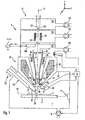
- FIG. 1 an example of a material processing system 1 is shown schematically. This is used to process a workpiece 3, namely a phase mask.
- This photomask is intended for use in a photolithographic process and has structures which are photographically coated on a radiation-sensitive layer ("resist"), with which a semiconductor substrate (“wafer”) is coated. Relative to the wavelength of the light used to transfer the structures from the mask to the semiconductor substrate, the critical dimensions of the structures are relatively small, therefore the structures on the mask are not merely embodied as alternately transparent and absorbing structures, but also a defined phase-shifting effect should provide the light used for imaging. Accordingly, the structures of the mask 3 must comply with predetermined limits for location-dependent material densities relatively accurately.
- the material separation takes place here by supplying a reaction gas ("precursor") in the vicinity of the selected location for processing.
- a reaction gas precursor
- An electron beam of primary electrons is simultaneously directed to the selected location, the primary electrons themselves or by these backscattered or secondary electrons released from the workpiece activating the reaction gas, so that components of the reaction gas are deposited at the selected location or in its vicinity, whereby the desired material deposition takes place in the region of the selected location.
- the removal of material takes place in a similar manner, although a different reaction gas is supplied, which is activated by the primary electrons or the resulting backscatter or secondary electrons such that it reacts at the selected location or its vicinity with the material of the workpiece and components thereof in a transferred gaseous or vaporous compound, so that they remove from the workpiece and finally the desired Material removal occurs in the area of the selected location.
- the workpiece 3 is fixedly mounted on a workpiece holder 5.
- Workpiece holder 5 and workpiece 3 are arranged in a processing chamber 7, which by means of a turbomolecular pump 9 and a in FIG. 1 not shown forepump is evacuated.
- a spatial position of the workpiece holder 5 relative to the processing chamber is by means of in FIG. 1 not shown drives in the three spatial directions x, y, z displaced.
- a plurality of laser interferometers 11 are provided to detect the position of the workpiece holder 5 relative to the processing chamber 7.
- an electron microscope 15 is mounted so that its optical axis 17 extends in the z-direction and an object plane 19 of the electron microscope 15 within the processing chamber 7 sets.
- the workpiece holder 5 is positioned within the processing chamber 7 such that a surface 21 of the workpiece 3 is arranged substantially in the object plane 19 of the electron microscope 15.
- the electron microscope 15 comprises an electron-emitting electron source 23 and a magnetic coil 25 acting as a condenser, in order to form from the emitted electrons an electron beam which is directed downwards along the axis 17.
- An objective lens 27 of the electron microscope 15 comprises an upper pole piece 29 and a lower pole piece 31, between which a winding 32 is provided and which define a Polschuhspalt to the axis 17. The objective lens 27 focuses the electron beam in the object plane 19.
- deflection windings 35 are provided to deflect the electron beam from the optical axis 17 of the electron microscope 15 in the x and y directions. A current through the deflection windings 35 and thus the deflection of the electron beam in the x and y direction is adjusted by means of a controller 37.
- a secondary electron detector 39 is arranged within the processing chamber 7, the detection signal of which is read out by the controller 37.
- the controller 37 controls the deflection windings 35 such that the electron beam systematically scans this region and those registered by the detector 39 as a function of the deflection Intensities are stored by controller 37 for further processing or output to a display device.
- Another secondary electron detector 41 which is also read out by the controller 37, is arranged inside the electron microscope 15 concentrically about its axis 19. The latter is arranged within a jet tube 43, which is symmetrical and conically tapered downwards relative to the axis 17 and which ends towards the object plane 19 in a collar 45 extending radially away from the axis at the level of the end of the lower pole piece 31. Between the collar 45 and the object plane 19, a diaphragm 47 is arranged with a bore 49 of 5 mm in diameter. There are controllable by the controller 37 and in FIG. 1 Voltage sources not shown provided to set the beam tube 43 and the aperture 47 to adjustable electrical potentials.
- the jet pipe 43 rests on a potential of 8 kV and the aperture 47 at ground potential. This creates between the collar 45 and the aperture 47 an electric field, which acts on a retarding and focusing on the primary electrons of the electron beam and on the other secondary electrons, which emerge from the workpiece 3 and move in an axis 17 enclosing solid angle area accelerates, so that they move with increased kinetic energy along the axis 17 upwards and meet the secondary electron detector 41 and are registered by this.
- the detector 41 for taking the electron microscopic images of the workpiece 3 and the other secondary electron detector 39 out of operation, since then necessary for the operation of the detector 39 electrostatic acceleration field, the focusing of the primary electrons on the workpiece 3 not disturbs.
- the secondary electron detector disposed in the processing chamber 39 may be disposed at a location not optimal for the operation thereof in the processing chamber, which, however, makes it possible to provide a comparatively small distance between the iris 47 and the object plane 19. This in turn allows a particularly fine focusing of the electron beam in the object plane 19 and thus a particularly high spatial resolution of the electron microscope 15.
- an energy-resolving photon detector 51 is arranged in the processing chamber, which detects energy-resolved X-radiation, which emerges from the workpiece 3 in the region of the axis 17.
- a gas supply arrangement 53 is flanged on the vacuum jacket 13 of the processing chamber 7, in addition to the electron microscope 15, a gas supply arrangement 53 is flanged.
- This comprises a plurality of gas feeds 55, each having a cannula 57 for directing a reaction gas in the processing chamber to the workpiece 3, including exit ends 59 of the cannulas 57 about 0.5 mm above the object plane 19 and 1 to 2 mm away from the Axis 17 are arranged.
- the gas supply assembly 53 is in the FIGS. 2 to 4 shown in detail and includes four symmetrically about an axis 58 arranged gas supply 55, of which two in FIG. 2 are visible.
- the cannulas 57 have an inner diameter of 0.7 mm to 1.5 mm and a corresponding outer diameter of 1.0 mm to 1.8 mm.
- An entrance end 61 of the cannula 57 opposite to the exit end 59 arranged in the vicinity of the axis 17 of the electron microscope 15 is received in an end wall 63 of a round tube 65 having an inner diameter of 4 mm.
- an annular sealing ring 71 is provided, which abuts both an inner wall 69 of the tube 65 and on an inner surface 73 of the end wall 63 of the tube.
- the sealing ring 71 is part of a valve 72 which selectively blocks and releases a gas flow from the interior of the tube 65 into the cannula 57.
- a valve body 75 In a gas flow obstructing position of the valve 72, a valve body 75 is pressed with its end face against the sealing ring 71, wherein a contact surface between the sealing ring 71 and the end face of the valve body 75 in FIG. 4 is indicated by a dashed line 76.
- valve body 75 In the gas flow releasing position of the valve 72, the valve body 75 is spaced from the sealing ring 71, as shown in FIG FIG. 3 shown with dashed lines.
- valve body 75 has a square cross-section with rounded corners, so that the valve body is guided with its rounded corners on the inner casing 69 of the tube 65, while between each pair of rounded corners, a portion of the valve body 75 an enlarged distance from the inner shell 69 of the tube 65 to provide four passage cross-sections 79 through which the reaction gas flow around the valve body 75 in the interior of the tube 65 and then can enter in the remote from the sealing ring 71 position of the valve body 75 in the cannula 57.
- the valve 72 is actuated by a rod 81 which extends coaxially with the tube 65 and at one end of the valve body 75 is fastened and at the other end a piston 83 is fixed, which is slidably mounted within a pneumatic cylinder 85.
- the pneumatic cylinder 85 has two compressed air connections 87 to which optionally compressed air is applied to either press the valve body 75 against the seal 71 and thus obstruct the flow of gas into the cannula or remove it from the seal 71 and thus the gas flow in the Release cannula.
- the reaction gas is fed to the interior of the tube 65 via a connection 89, which is inserted into the tube 65 via a T-piece.
- a flange 91 for connection to the vacuum jacket 13 of the processing chamber 7 encloses the tubes 65 of the four gas feeders 55.
- this flange 91 is one end of a bellows 93 vacuum-tight connected, the other end is vacuum-tightly connected to a flange 95, which pass through the tubes 65 individually and vacuum-tight, the tubes 65 are also mechanically fixed to this flange 95.
- the distances between the flanges 91 and 95 can be changed and thus the positions of the exit ends 95 of the cannulas 57 relative to the object plane 19 and the axis 17 of the electron microscope 15 adjust when the gas supply assembly 53 on the vacuum jacket 13 of the processing chamber 7 is fixed.
- the threaded rods 97 continue to carry a plate 101, on which the compressed air cylinder 85 are set to actuate the valves 72.
- the tubes 65 At their ends remote from the cannula 57, the tubes 65 each pass into a bellows 103, which is closed in a vacuum-tight manner by a plate 105.
- the rod 81 On the plate 105, the rod 81 is fixed for displacement of the valve body 75.
- the plate 105 in turn is coupled to the piston 83 in the air cylinder 85 via a rod 106.
- the bellows is stretched or compressed, which in turn leads to a displacement of the valve body 75 in the tube 65 and thus to actuation of the valve 72.
- valve 72 When the valve 72 is transitioned from its open state to its gas flow blocking state at a certain time, it is desirable that substantially no reaction gas escape from the exit end 59 of the cannula 57 from that point on. However, at the time of complete closure of the valve 72 in the space between the valve body 75 and the outlet end 59 of the cannula 57, a residual reaction gas is still present, which subsequently still emerge from the outlet end 59 of the cannula 57 and thus can lead to a further reaction with the workpiece 3.
- the volume of the gas space formed between the valve body 75 and the outlet end 59 is comparatively small. It should be noted that a certain volume of this space can not be avoided, since the reaction gas is guided by means of the cannula 57 to the reaction site near the workpiece 3.
- the cannula 57 must have a certain gas conductance and thus a certain cross-section at least in order to allow a desired gas flow towards the workpiece 3. In this case, however, it is possible that the cross section of the cannula 57 is smaller than a minimum cross section of the valve 72, whereby the advantage arises that in the vicinity of the processing location no bulky components such as the valve body 75 are to be arranged.
- the valve 72 and its transition into the cannula 57 are now designed so that in the closed state of the valve 72, the gas space between the valve body 75 and the outlet end 59 of the cannula 57 is not substantially greater than the volume of the cannula 57 itself.
- the volume of this gas space is composed of the volume of the cannula 57 and a volume which is limited axially on the one hand by the inner surface 73 of the end wall 63 of the tube 65 and on the other hand by the end face of the valve body 75 facing the cannula and which radially through the sealing ring 71 is limited.
- the small radius of the sealing ring 71 is about 0.5 mm and the inner radius of the sealing ring 71 is about 1.0 mm.
- the volume between the valve body 75 and the end wall 73 has a value of about 1.5 mm 3 .
- the cannula has a volume of about 40 mm 3 with an inner diameter of 1.0 mm and a length of 50 mm.
- the volume between the outlet end of the cannula 59 and the end face of the valve body 75 in the closed Position of the valve 72 thus a volume of 41.5 mm.
- registered length 1 is the sum of the length of the cannula and the small diameter of the sealing ring 71 and is thus about 51 mm.
- a value c of a ratio of volume of the gas space divided by cross section of the cannula 57 at its exit end 59 times the length ⁇ c V A ⁇ l > thus has a value of about 1.05.
- the valve 72 and its transition into the cannula 57 the volume of the gas space between the outlet end of the cannula 59 and the valve body 75 in its gas flow obstructing position is only 1.05 times greater than the predetermined by the cannula 57 itself volume.
- a period of time during which reaction gas still exits the outlet end 59 of the cannula in a significant amount after closing the valve is almost minimal.
- reaction gases The provision of the reaction gases will be described below with reference to FIG. 2 further explained.
- the pipe 89 communicating with the interior of the pipe 65 is connected via a hose 110 to a reservoir 111 in which a starting material 113 of the reaction gas is accommodated.
- Each gas supply 55 is associated with a separate reservoir 111 with corresponding starting material 113 contained therein.
- the starting material 113 is present in the reservoir 111 in solid or liquid form.
- the reaction gas is formed by evaporation, evaporation or sublimation of the starting material.
- valve 72 When valve 72 is closed, a partial pressure of reaction gas, which is essentially equal to the vapor pressure of starting material 113, is formed in the contiguous gas space from reservoir 111 to valve 72. If now the valve 72 is opened, a flow of the reaction gas, so that this at the outlet end 59 exits the cannula 57.
- This gas flow is essentially limited by the gas guide value 57 of the cannula, since the cross section of the cannula 57 is substantially smaller than cross sections of the other components of the gas line system, such as the cross section of the tube 65, the cross section of the nozzle 89 or the tube 110.
- the gas conductance of the cannula is approximately 2 ⁇ 10 -2 l / sec. If a value of 0.1 mbar is assumed for the gas pressure of the starting material 113, a value of 10 -3 mbarl / sec results for the gas flow Q through the cannula into the processing chamber 7.
- the density of the reaction gas will be substantially higher than in other regions of the processing chamber remote from the exit end 59. Therefore, the exit end 59 is located at only a small distance from the work site 3 to be processed, and the electron beam directed to the work piece 3 can then excite the reaction gas to effectively react with the work piece.
- valve 72 not a metering valve but a two-position valve is used as valve 72, which can be transferred from a position substantially obstructing the gas flow into a position which substantially completely releases the gas flow.
- the valve body in this case moves briefly through intermediate positions that release the gas flow more or less, however, the valve is not designed to finely dose a gas flow.
- the gas flow through the cannula 57 is thus essentially given by the gas conductance of the cannula and the vapor pressure of the starting material 113.
- a temperature control device 115 is provided on the reservoir 111, for which purpose a plurality of windings 117 of a fluid circuit are mounted on the reservoir 111, which is driven by a heat / cooling machine 119.
- the heat / chiller 119 sets the temperature of the fluid flowing through the fluid circuit to a value that is set by a controller 121.
- the controller 121 further reads out a signal from a pressure sensor 123, which measures the gas pressure within the reservoir 111. Since this gas pressure is given substantially by the vapor pressure of the starting material 113, the controller 121 of the heating / cooling machine 119 will set a higher temperature than a current temperature to increase the temperature of the starting material 113 when the Conversely, the controller 121 of the heat / chiller 119 will dictate a lower temperature if the pressure measured by the sensor 123 is greater than the desired vapor pressure.
- the gas conductance of the cannula 57 is in this case adapted to the starting material 113 to be used such that the temperature of the starting material 113 is set lower than the operating temperature of the device or the room temperature to set the desired vapor pressure.
- the temperature of the starting material 113 is set higher than the operating or room temperature.
- the reaction gas evaporating or sublimating in the heated reservoir 111 from the surface of the starting material 113 is precipitated on walls of the gas supply 55 that are colder than the latter.
- gas supply assembly 53 is designed to eject two reaction gases, which are excited by the electron beam to such a reaction with each other that platinum-carbon composite material deposited on the workpiece 3 in the region to which the electron beam is directed.
- This is in the in FIG. 2 left reservoir 111 hydrogen peroxide as a solid at a temperature of minus 40 ° C included. At this temperature, the vapor pressure of hydrogen peroxide is 0.05 mbar.
- the hydrogen peroxide is released by the in FIG. 2 upper cannula 57 ejected toward the processing site.
- This cannula 57 has an inner diameter of 0.8 mm and a length of 50 mm, whereby its gas conductance is 1.6 ⁇ 10 -3 l / sec. With the valve 72 open, hydrogen peroxide thus flows out of the outlet end 59 in such an amount that about 52 monolayers of hydrogen peroxide can be deposited on the workpiece per second.
- This in FIG. 2 right reservoir contains cyclopentadienyl-trimethyl-platinum at a temperature of 20 degrees Celsius at which its vapor pressure is 0.05 mbar.
- Lower cannula 57 through which this gas flows to the processing site has an inner diameter of 1.4 mm and also a length of 5 mm, so that their conductance is 1.6 ⁇ 10 -3 1 / sec. Under these conditions, the gas cyclopentadienyl-trimethyl-platinum flows out of the cannula in such an amount that deposition of about 276 monolayers per second would occur on the workpiece.
- a pressure plate 121 which has a penetrated by the electron beam inner diameter of 1 mm.
- the pressure diaphragm 121 separates the vacuum space of the material processing system 1 into a vacuum space arranged below the pressure diaphragm 121 and comprising the processing chamber 7 and an intermediate vacuum space arranged above the pressure diaphragm 121.
- the vacuum space arranged above the pressure diaphragm 121 is subdivided further into partial vacuum chambers 125 and 127, which are pumped separately.
- the intermediate vacuum space 123 is separated by a Pumped turbomolecular pump 129 and bounded below by the pressure diaphragm 121 and up through a pressure diaphragm 131 with an inner diameter of 500 microns.
- the vacuum space 125 is pumped through an ion getter pump 133 and is bounded below by the pressure diaphragm 131 and up through another pressure diaphragm 135 with an inner diameter of 80 microns.
- the vacuum space 127 lying above the pressure diaphragm 135 is evacuated by a further ion getter pump 137 and contains the electron source 23 itself.
- a shutter 139 operated by a driver 140 is provided to completely close the pressure screen 131.
- the drive 140 is controlled by the controller 37 in such a way that the shutter 139 is only opened when a read out of the controller 37 pressure sensor 142 registered in the subspace 123 a pressure which is less than 10 -3 mbar.
- Seals 145 are provided to seal the pole pieces 29 and 31 from the jet tube 43, so that the coil 32 does not have to be arranged in vacuum to the objective lens 27.
- the electron microscope 15 it is possible with the electron microscope 15 to receive electron microscopic images of the workpiece 3 and thereby checking the progress of the machining of the workpiece.
- the electron microscopic images can be recorded when the reaction gas is not being conducted in the vicinity of the processing location, in which case particularly good vacuum conditions prevail in the processing chamber 7.
- the controller 37 switches the material processing system to an operating mode in which the turbomolecular pump 9 evacuating the processing chamber 7 is disabled. It is the processing chamber 7 then only by a in the FIG. 1 Not shown Vorpumpe the turbomolecular pump evacuated 9, wherein the gas pressure in the processing chamber can rise to about 1 mbar.
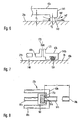
- An in FIG. 5 shown material processing system 1a in turn comprises a processing chamber 7a, in which a workpiece 3a on a workpiece holder 5a so arranged is that a surface 21a of the workpiece 3a lies in an object plane of an electron microscope 15a.
- a gas supply assembly 53a is provided to eject a plurality of reaction gases near a processing location which is in a range around a main axis 17a of the electron microscope 15a.
- the electron microscope 15a likewise comprises a downwardly conically tapered jet tube 43a, which ends towards the workpiece 3a in a radially extending collar 45a. Between the collar 45a and the workpiece 3a, in turn, an electrode aperture 47a is arranged, which, however, in contrast to the above-described Biespiel also serves as a pressure diaphragm for the separation of vacuum spaces.
- the electrode diaphragm 47a has an inner diameter of 200 ⁇ m. Although this small aperture diameter limits the field of view of the electron microscope, this results in other advantages.
- the aperture electrode 47a extends parallel to the surface of the workpiece 3a with a distance d 1 of 300 microns.
- the diaphragm electrode 47a further carries a projection 141 which extends annularly at a distance around the main axis 17a of the electron microscope 15a and has a plane surface 143 pointing toward the surface of the workpiece 3a and thus to the object plane 19a. Between the flat surface 143 and the sample surface or object plane 19a there is a distance d 2 of 75 ⁇ m.
- a vacuum subspace 148 is formed between the diaphragm electrode 47a and the workpiece, in which cannulas 57a of the gas supply arrangement 53a terminate.
- the cannulas 57a pass through the diaphragm electrode 47a from above.
- the vacuum part space 148 is sealed off from the remaining vacuum space of the processing chamber 7a by the projection 141, although a certain amount is created by the gap d 2 between the plane surface 143 and the surface of the workpiece 3a Leakage rate is provided as indicated by arrows 147 in FIG FIG. 6 is indicated.
- FIG. 7 is a variant of the Figures 5 and 6 shown embodiment shown schematically.
- a diaphragm electrode 47b carries at its axially projecting projection 141b towards the object plane a sealing ring 151 made of the material "Viton" or another suitable elastomer material which is designed to rest on the workpiece.
- the material of the sealing ring 151 is selected such that a displacement of the workpiece 3a relative to the diaphragm electrode 47b does not damage the workpiece 3b.
- the subspace 148 may be evacuated by lowering the workpiece fixture together with the workpiece 3b mounted thereon such that a sufficient distance is provided between the sealing ring 151 and the surface 21b of the workpiece 3b to allow the gas to escape into the subspace 148.
- a suction nozzle 171 which extends away from the diaphragm electrode 47 in the direction of the object plane 19b and is closed by a switchable valve 173, which in the open state, the subspace 148 with the vacuum space of Processing chamber connects and in its closed state, these two vacuum spaces separated from each other.
- FIG. 8 shows a variant of a valve of a gas supply arrangement. Unlike the in FIG. 3 valve shown seals a valve body 75c of a FIG. 8 shown valve 72c directly against an inlet end 61c of a cannula 57c from.
- the valve body 75c made of an elastomer material is embedded in a holder 161, which is connected to a rod 81c for actuating the valve 72c.
- the cannula 57c protrudes with its entrance end 61c through an end wall 63c of a tube 65c into the interior of the tube 65c, so that an end face of the entrance end 61c of the cannula 57c may come into direct contact with the valve body 75c for gas flow from inside the tube 65c into the cannula 57c to close.
- FIG. 9 shows a variant of in FIG. 2 illustrated gas supply arrangement, in which case the gas supply is modified in the tube on which the cannula is held.
- the reaction gas to be supplied via a nozzle 89 c is supplied to a tube 65 c, in which a rod 81 c for actuating an in FIG. 9 Not shown valve body is held.
- the tube 65c passes through a flange 95c and is mechanically held on this.
- One end of the tube 65 is vacuum-tightly connected to a bellows 103c, and this connects via a pipe spacer 181 vacuum-tight to a cross member 183, wherein the connection between the pipe spacer 181 and the cross member 183 can be done for example by welding.
- the valve body operating rod 81c is also fixed by welding.
- the cross member 183 is fixed to a cylinder 85c of a piston-cylinder unit whose piston 83c is coupled to the flange 95c via a rod 106c.
- the piston 83c By supplying compressed air via ports 87c to the piston-cylinder unit, the piston 83c can be displaced within the cylinder 85c, which also results in a displacement of the rod 81c within the tube 81c, since the bellows 113 is compressible.
- connection 89c On the side facing away from the pipe spacer 181 side of the cross member 183 of the connection 89c for the gas to be supplied is also connected vacuum-tight.
- the cross member is penetrated by openings 185, so that the gas from the connecting piece 89c can pass into the interior of the tube 85c.
- tempering device When related to FIG. 2 described tempering device are a plurality of windings of a cooling liquid or heat fluid flows through, and these transfer the heat or cold directly to the interior of the reservoir.
- Peltier elements intervene to reach even lower temperatures within the reservoir.
- An employment of the material processing system described above can be done as follows. This is provided here for the machining of a workpiece, in particular the repair of a photomask.
- the method is preferably fully automated by means of a control computer for controlling the components of the material processing system.
- a defective photomask is first scanned by conventional optical or corpuscular-beam optical devices, such as an AIMS device, to determine the coordinates of the mask defects.
- the data containing these coordinates are entered into the control computer and converted by means of input translators of the control computer into a data format suitable for the material processing system in the control computer.
- the photomask to be processed is introduced manually, semi-automatically or automatically into the processing chamber of the material processing system.
- the photomask to be processed in a container commonly used for mask transport such as a so-called "SMIF box", brought by means of a computer-controlled mask loader to an input station of the processing system, introduced into the input station and removed from the container to either there be transferred directly into the processing chamber of the material processing system or stored for further processing in a starting station of the material processing system.
- a container commonly used for mask transport such as a so-called "SMIF box”
- the defect areas of the photomask can be located on the basis of the defect coordinates by moving the workpiece holder holding the photomask, ie brought into the area of the electron beam, the position of the workpiece being controlled relative to the electron microscope with the aid of the laser interferometer.
- the surface becomes of the workpiece is then scanned to obtain a high resolution image of the defect to be processed.
- a characterization of the materials in particular an elemental analysis, can take place on the surface of the defect sites of the photomask. Illustration and / or EDX analysis can be performed manually, semi-automatically or fully automatically.
- a defect quantity to be repaired is determined by the control computer. The steps necessary for repairing the defect size are determined by the control computer by allocating the defect size to a repair process and repair parameters stored in the control computer.
- the necessary steps to repair the defect location and parameters of the repair process are preferably carried out automatically by the control computer.
- the processed defect site is again scanned electronically and imaged.
- the image obtained is compared with the target image and, with a predetermined degree of deviation of the images, further repair steps are performed or the photomask repair is terminated, whereupon the repaired photomask is provided as the end product of the process for further use.
- the photomask can be a phase-shifting mask.
- it is also intended to process binary masks in which the structures are formed, for example, by chromium-containing regions deposited on a glass substrate or SiO 2 substrate.
- these masks can also have so-called "proximity corrections", ie particularly small structures which can be resolved with the aid of the electron microscope.
- the technique described above in which the reservoir for the starting material is cooled, can also be used in gas supplies which do not work with a cannula or which do not have a two-position valve but, for example, a metering valve.
Landscapes
- Chemical & Material Sciences (AREA)
- Analytical Chemistry (AREA)
- Physics & Mathematics (AREA)
- Engineering & Computer Science (AREA)
- Plasma & Fusion (AREA)
- Chemical Vapour Deposition (AREA)
- Welding Or Cutting Using Electron Beams (AREA)
- Physical Or Chemical Processes And Apparatus (AREA)
- ing And Chemical Polishing (AREA)
Claims (15)
- Système de traitement de matériau, comprenant :- une chambre de traitement (7),- une fixation de pièce à usiner (5) pour fixer une pièce à usiner (3) à traiter dans la chambre de traitement (7), de telle sorte qu'une zone de surface de la pièce à usiner (3) peut être disposée dans un plan objet (19),- un microscope électronique (15) avec- une source d'électrons (23) pour générer un faisceau d'électrons,- au moins une lentille de focalisation (27) pour concentrer le faisceau d'électrons sur le plan objet (19) et- au moins un détecteur d'électrons (41, 39) pour la détection d'électrons sortant d'une zone du plan objet (19) ;- un agencement d'alimentation en gaz (53) pour amener au moins un gaz réactif, pouvant être mis en réaction avec la pièce à usiner (3) au moyen du faisceau d'électrons focalisé,dans lequel, le microscope électronique (15) comporte au moins une paire d'obturateurs à pression (121, 131 ; 47a) avec chacun une ouverture (49) traversée par le faisceau d'électrons, l'un des deux obturateurs (121 ; 47a) séparant en partie un espace à vide de la chambre de traitement (7) d'un espace à vide intermédiaire (123) et un second des deux obturateurs (131) séparant en partie l'espace à vide intermédiaire (123) d'un espace à vide (123, 125, 127) qui contient l'émetteur électronique (23), un agencement de pompe à vide (129) présentant un premier raccord avec l'espace à vide intermédiaire (123), et un premier détecteur d'électrons (41) étant disposé dans l'espace à vide intermédiaire (123),
dans lequel un composante (141) du microscope électronique, le plus proche du plan objet (19a), présente une surface d'extrémité (143), qui entoure en forme d'anneau le faisceau d'électrons et est orientée de façon essentiellement plane sur le plan objet (19a), et
dans lequel la surface d'extrémité (143) du composant (141) du microscope électronique (15a) la plus proche du plan objet (19a) est réalisée pour présenter un écartement (d2) de moins de 100µm, en particulier de moins de 50µm, par rapport au plan objet (19a). - Système de traitement de matériau suivant la revendication 1, dans lequel une lentille de focalisation (27) du microscope électronique (15) la plus proche du plan objet (19) est disposée entre le premier détecteur (41) et le plan objet (19).
- Système de traitement de matériau suivant l'une des revendications 1 et 2, dans lequel une pompe turbomoléculaire séparée (129) est associée au premier raccord pour pomper l'espace à vide intermédiaire (123).
- Système de traitement de matériau suivant l'une des revendications 1 à 3, dans lequel le composant (141b) du microscope électronique le plus proche du plan objet (19b) est configuré sous forme de joint (151) pour placement sur la pièce à usiner (3b).
- Système de traitement de matériau suivant la revendication 4, dans lequel la fixation de pièce à usiner est réalisée pour écarter la pièce à usiner du contact sur le composant configuré sous forme de joint.
- Système de traitement de matériau suivant l'une des revendications 1 à 5, dans lequel l'obturateur à pression (47a) est disposé entre la lentille de focalisation (27a) du microscope électronique (15a) la plus proche du plan objet (19a) et le plan objet (19a).
- Système de traitement de matériau suivant l'une des revendications 1 à 6, dans lequel un second détecteur d'électrons (39) est disposé dans la chambre de traitement (7).
- Système de traitement de matériau suivant l'une des revendications 1 à 7, dans lequel l'agencement de pompe à vide présente un second raccord (9) à l'espace à vide de la chambre de traitement (7).
- Système de traitement de matériau suivant la revendication 8, comprenant en outre une commande (37) pour la commutation de l'agencement de pompe à vide (9, 129) entre un premier et un second mode de fonctionnement, la chambre de traitement (7) pouvant être soumise à un vide plus intense dans le premier mode de fonctionnement que dans le second mode de fonctionnement, par l'intermédiaire du second raccord (9).
- Système de traitement de matériau suivant la revendication 9, dans lequel une pompe turbomoléculaire séparée (9) est associée au second raccord, la commande (37) et la pompe turbomoléculaire séparée (9) étant configurées de sorte que la pompe turbomoléculaire séparée (9) est hors service dans le second mode de fonctionnement.
- Système de traitement de matériau suivant l'une des revendications 9 et 10, dans lequel le système de traitement de matériau est configuré de sorte qu'une pression de gaz dans la chambre de traitement (7) est inférieure à environ 0,05 mbar dans le premier mode de fonctionnement et supérieure à 0,1 mbar dans le second mode de fonctionnement.
- Système de traitement de matériau suivant l'une des revendications 1 à 11, comprenant en outre un détecteur de photons (51) à détection d'énergie, en particulier un détecteur à rayons X, pour la détection de photons sortant de la pièce à usiner (3) dus à une interaction avec le faisceau d'électrons.
- Procédé de traitement d'une pièce à usiner, comprenant :- la prise de vue d'une image au microscope électronique d'une zone de la pièce à usiner par direction d'un faisceau d'électrons sur une pluralité d'endroits à l'intérieur de la zone et enregistrement d'électrons secondaires sortant de la pièce à usiner en fonction des endroits sur lesquels est dirigé le faisceau d'électrons,- détermination d'au moins un endroit à l'intérieur de la zone de la pièce à usiner auquel du matériau de la pièce à usiner doit être enlevé ou auquel du matériau doit être séparé de la pièce à usiner,- amenée d'au moins un gaz réactif en direction de la zone de la pièce à usiner,- direction du faisceau d'électrons sur l'au moins un endroit déterminé de la pièce à usiner, pour mettre en réaction l'au moins un gaz réactif avec la pièce à usiner, le procédé étant mis en oeuvre en utilisant le système de traitement de matériau suivant l'une des revendications 1 à 12.
- Procédé suivant la revendication 13, dans lequel la prise de vue de l'image au microscope électronique s'effectue après l'activation de la réaction et dans lequel au moins un autre endroit à l'intérieur de la zone de la pièce à usiner est défini en fonction de l'image enregistrée, endroit auquel du matériau doit être enlevé de la pièce à usiner ou doit être séparé de cette dernière.
- Procédé suivant l'une des revendications 13 à 14, dans lequel la pièce à usiner est un masque pour l'utilisation dans un procédé lithographique, en particulier un photomasque et d'une autre façon préférentielle un masque à phases.
Applications Claiming Priority (2)
| Application Number | Priority Date | Filing Date | Title |
|---|---|---|---|
| DE2002108043 DE10208043B4 (de) | 2002-02-25 | 2002-02-25 | Materialbearbeitungssystem und Materialbearbeitungsverfahren |
| EP03742580A EP1479091A2 (fr) | 2002-02-25 | 2003-02-25 | Systeme et procede de traitement de materiau, et dispositif d'amenee de gaz y relatif |
Related Parent Applications (2)
| Application Number | Title | Priority Date | Filing Date |
|---|---|---|---|
| EP03742580.8 Division | 2003-02-25 | ||
| EP03742580A Division EP1479091A2 (fr) | 2002-02-25 | 2003-02-25 | Systeme et procede de traitement de materiau, et dispositif d'amenee de gaz y relatif |
Publications (3)
| Publication Number | Publication Date |
|---|---|
| EP1892748A2 EP1892748A2 (fr) | 2008-02-27 |
| EP1892748A3 EP1892748A3 (fr) | 2010-03-17 |
| EP1892748B1 true EP1892748B1 (fr) | 2011-10-19 |
Family
ID=27740398
Family Applications (2)
| Application Number | Title | Priority Date | Filing Date |
|---|---|---|---|
| EP07022228A Expired - Lifetime EP1892748B1 (fr) | 2002-02-25 | 2003-02-25 | Système de traitement de matériau et procédé de traitement de matériau |
| EP03742580A Withdrawn EP1479091A2 (fr) | 2002-02-25 | 2003-02-25 | Systeme et procede de traitement de materiau, et dispositif d'amenee de gaz y relatif |
Family Applications After (1)
| Application Number | Title | Priority Date | Filing Date |
|---|---|---|---|
| EP03742580A Withdrawn EP1479091A2 (fr) | 2002-02-25 | 2003-02-25 | Systeme et procede de traitement de materiau, et dispositif d'amenee de gaz y relatif |
Country Status (4)
| Country | Link |
|---|---|
| EP (2) | EP1892748B1 (fr) |
| JP (1) | JP4058002B2 (fr) |
| DE (1) | DE10208043B4 (fr) |
| WO (1) | WO2003071578A2 (fr) |
Cited By (1)
| Publication number | Priority date | Publication date | Assignee | Title |
|---|---|---|---|---|
| US11764036B2 (en) | 2018-12-20 | 2023-09-19 | Carl Zeiss Microscopy Gmbh | Operating a gas supply device for a particle beam device |
Families Citing this family (31)
| Publication number | Priority date | Publication date | Assignee | Title |
|---|---|---|---|---|
| ATE512455T1 (de) * | 2004-04-15 | 2011-06-15 | Zeiss Carl Sms Gmbh | Vorrichtung und methode zur untersuchung oder modifizierung einer oberfläche mittels ladungsträgerstrahls |
| US7232997B2 (en) | 2004-04-15 | 2007-06-19 | Nawotec Gmbh | Apparatus and method for investigating or modifying a surface with a beam of charged particles |
| EP1774538A4 (fr) * | 2004-07-29 | 2012-06-06 | Omniprobe Inc | Systeme d'injection de gaz a elements multiples pour instruments a faisceau de particules chargees |
| US7312448B2 (en) | 2005-04-06 | 2007-12-25 | Carl Zeiss Nts Gmbh | Method and apparatus for quantitative three-dimensional reconstruction in scanning electron microscopy |
| DE102006043895B9 (de) | 2006-09-19 | 2012-02-09 | Carl Zeiss Nts Gmbh | Elektronenmikroskop zum Inspizieren und Bearbeiten eines Objekts mit miniaturisierten Strukturen |
| DE102006054695B4 (de) * | 2006-11-17 | 2014-05-15 | Carl Von Ossietzky Universität Oldenburg | Verfahren zur Regelung nanoskaliger elektronenstrahlinduzierter Abscheidungen |
| DE102007054073A1 (de) | 2007-11-13 | 2009-05-14 | Carl Zeiss Nts Gmbh | System und Verfahren zum Bearbeiten eines Objekts |
| DE102007054074A1 (de) | 2007-11-13 | 2009-05-14 | Carl Zeiss Nts Gmbh | System zum Bearbeiten eines Objekts |
| TWI479570B (zh) | 2007-12-26 | 2015-04-01 | 奈華科技有限公司 | 從樣本移除材料之方法及系統 |
| DE102008009640A1 (de) | 2008-02-18 | 2009-08-27 | Carl Zeiss Nts Gmbh | Prozessierungssystem |
| DE102008011530B4 (de) * | 2008-02-28 | 2012-05-03 | Carl Zeiss Sms Gmbh | Verfahren zum Bearbeiten eines Objekts mit miniaturisierten Strukturen |
| DE102008011531B4 (de) * | 2008-02-28 | 2011-12-08 | Carl Zeiss Sms Gmbh | Verfahren zum Bearbeiten eines Objekts mit miniaturisierten Strukturen |
| EP2257853B1 (fr) * | 2008-02-28 | 2012-07-25 | Carl Zeiss SMS GmbH | Procédé de traitement d un objet comportant des structures miniaturisées |
| DE102008040426B4 (de) | 2008-07-15 | 2015-12-24 | Carl Zeiss Microscopy Gmbh | Verfahren zur Untersuchung einer Oberfläche eines Objekts |
| DE102008049655A1 (de) | 2008-09-30 | 2010-04-08 | Carl Zeiss Nts Gmbh | Partikelstrahlsystem und Verfahren zum Betreiben desselben |
| DE102009045008A1 (de) | 2008-10-15 | 2010-04-29 | Carl Zeiss Smt Ag | EUV-Lithographievorrichtung und Verfahren zum Bearbeiten einer Maske |
| DE102009033319B4 (de) | 2009-07-15 | 2019-02-21 | Carl Zeiss Microscopy Gmbh | Partikelstrahl-Mikroskopiesystem und Verfahren zum Betreiben desselben |
| JP5719019B2 (ja) * | 2010-06-03 | 2015-05-13 | カール ツァイス エスエムエス ゲーエムベーハー | フォトリソグラフィマスクの性能を判断する方法 |
| JP5481401B2 (ja) * | 2011-01-14 | 2014-04-23 | 株式会社日立ハイテクノロジーズ | 走査電子顕微鏡 |
| DE102011018460A1 (de) | 2011-04-21 | 2012-10-25 | Carl Zeiss Nts Gmbh | Prozessierungssystem |
| DE102012001267A1 (de) | 2012-01-23 | 2013-07-25 | Carl Zeiss Microscopy Gmbh | Partikelstrahlsystem mit Zuführung von Prozessgas zu einem Bearbeitungsort |
| DE102020120940B4 (de) | 2020-08-07 | 2023-12-28 | Carl Zeiss Smt Gmbh | Bearbeitungsanordnung, Vorrichtung, Verfahren, Spülplatte und Verwendung |
| DE102020124307B4 (de) | 2020-09-17 | 2026-01-29 | Carl Zeiss Smt Gmbh | Vorrichtung zum Analysieren und/oder Bearbeiten einer Probe mit einem Teilchenstrahl und Verfahren |
| DE102020124306B4 (de) * | 2020-09-17 | 2022-08-11 | Carl Zeiss Smt Gmbh | Vorrichtung zum Analysieren und/oder Bearbeiten einer Probe mit einem Teilchenstrahl und Verfahren |
| DE102021120913B3 (de) | 2021-08-11 | 2023-02-09 | Carl Zeiss Smt Gmbh | Vorrichtung zum Analysieren und/oder Bearbeiten einer Probe mit einem Teilchenstrahl und Verfahren |
| DE102021132833A1 (de) | 2021-12-13 | 2023-06-15 | Carl Zeiss Microscopy Gmbh | Gaszuführungseinrichtung, System mit einer Gaszuführungseinrichtung sowie Teilchenstrahlgerät mit einer Gaszuführungseinrichtung oder dem System |
| DE102021132834B4 (de) | 2021-12-13 | 2024-08-08 | Carl Zeiss Microscopy Gmbh | Gasreservoir, Gaszuführungseinrichtung mit einem Gasreservoir und Teilchenstrahlgerät mit einer Gaszuführungseinrichtung |
| DE102021132832A1 (de) | 2021-12-13 | 2023-06-15 | Carl Zeiss Microscopy Gmbh | Gaszuführungseinrichtung, Teilchenstrahlgerät mit einer Gaszuführungseinrichtung sowie Verfahren zum Betrieb der Gaszuführungseinrichtung und des Teilchenstrahlgeräts |
| DE102021214447A1 (de) | 2021-12-15 | 2023-06-15 | Carl Zeiss Smt Gmbh | Elektronenmikroskop zum Untersuchen einer Probe |
| DE102022118006B3 (de) | 2022-07-19 | 2023-11-16 | Carl Zeiss Microscopy Gmbh | Verfahren zum Bearbeiten einer Probe, Teilchenstrahlsystem und Computerprogrammprodukt |
| DE102022208597B4 (de) * | 2022-08-18 | 2026-03-05 | Carl Zeiss Microscopy Gmbh | Vorrichtung zum Abbilden und Bearbeiten einer Probe mit einem fokussierten Teilchenstrahl |
Family Cites Families (21)
| Publication number | Priority date | Publication date | Assignee | Title |
|---|---|---|---|---|
| EP0106510B1 (fr) * | 1982-10-19 | 1991-11-13 | Varian Associates, Inc. | Dispositif de traitement comportant des moyens de production d'un vide localisé |
| US4698236A (en) * | 1984-10-26 | 1987-10-06 | Ion Beam Systems, Inc. | Augmented carbonaceous substrate alteration |
| DE3890362T1 (de) * | 1987-05-11 | 1989-10-19 | Microbeam Inc | Maskenreparatur unter verwendung eines optimierten fokussierten ionenstrahlsystems |
| JPH0262039A (ja) * | 1988-08-29 | 1990-03-01 | Hitachi Ltd | 多層素子の微細加工方法およびその装置 |
| EP0361460A3 (fr) * | 1988-09-29 | 1990-08-01 | Sony Corporation | Méthode pour la fabrication d'un motif |
| JPH03124463U (fr) * | 1990-03-28 | 1991-12-17 | ||
| US5683547A (en) * | 1990-11-21 | 1997-11-04 | Hitachi, Ltd. | Processing method and apparatus using focused energy beam |
| US5188705A (en) * | 1991-04-15 | 1993-02-23 | Fei Company | Method of semiconductor device manufacture |
| DE4204650C1 (fr) * | 1992-02-15 | 1993-07-08 | Hoffmeister, Helmut, Dr., 4400 Muenster, De | |
| DE4421517A1 (de) * | 1993-06-28 | 1995-01-05 | Schlumberger Technologies Inc | Verfahren zum Abtrag oder Auftrag von Material mittels eines Partikelstrahls und Vorrichtung zu seiner Durchführung |
| US5435850A (en) * | 1993-09-17 | 1995-07-25 | Fei Company | Gas injection system |
| DE4340956C2 (de) * | 1993-12-01 | 2002-08-22 | Advantest Corp | Verfahren und Vorrichtung zur Bearbeitung einer Probe |
| JP3310136B2 (ja) * | 1994-09-17 | 2002-07-29 | 株式会社東芝 | 荷電ビーム装置 |
| US5747818A (en) * | 1996-10-21 | 1998-05-05 | Schlumberger Technologies Inc. | Thermoelectric cooling in gas-assisted FIB system |
| US6042738A (en) * | 1997-04-16 | 2000-03-28 | Micrion Corporation | Pattern film repair using a focused particle beam system |
| AU2260899A (en) * | 1998-02-06 | 1999-08-23 | Northern Edge Associates Inc. | Method and apparatus for deposition of three dimensional object |
| US5911711A (en) * | 1998-06-29 | 1999-06-15 | Becton, Dickinson And Company | Lubricant system for hypodermic needles and method for its application |
| DE19851622A1 (de) * | 1998-11-09 | 2000-05-18 | Fraunhofer Ges Forschung | Verfahren zum Untersuchen und/oder zum Modifizieren von Oberflächenstrukturen einer Probe |
| US6268608B1 (en) * | 1998-10-09 | 2001-07-31 | Fei Company | Method and apparatus for selective in-situ etching of inter dielectric layers |
| WO2001003145A1 (fr) * | 1999-07-02 | 2001-01-11 | Applied Materials, Inc. | Appareil et technique permettant d'examiner un echantillon avec un faisceau de particules chargees |
| DE10042098A1 (de) * | 2000-08-26 | 2002-03-14 | Deutsche Telekom Ag | Gasversorgung für Additive Lithographie |
-
2002
- 2002-02-25 DE DE2002108043 patent/DE10208043B4/de not_active Expired - Lifetime
-
2003
- 2003-02-25 EP EP07022228A patent/EP1892748B1/fr not_active Expired - Lifetime
- 2003-02-25 JP JP2003570383A patent/JP4058002B2/ja not_active Expired - Lifetime
- 2003-02-25 WO PCT/EP2003/001923 patent/WO2003071578A2/fr not_active Ceased
- 2003-02-25 EP EP03742580A patent/EP1479091A2/fr not_active Withdrawn
Cited By (1)
| Publication number | Priority date | Publication date | Assignee | Title |
|---|---|---|---|---|
| US11764036B2 (en) | 2018-12-20 | 2023-09-19 | Carl Zeiss Microscopy Gmbh | Operating a gas supply device for a particle beam device |
Also Published As
| Publication number | Publication date |
|---|---|
| DE10208043B4 (de) | 2011-01-13 |
| JP2005518638A (ja) | 2005-06-23 |
| EP1892748A2 (fr) | 2008-02-27 |
| WO2003071578A3 (fr) | 2004-01-08 |
| WO2003071578A2 (fr) | 2003-08-28 |
| EP1479091A2 (fr) | 2004-11-24 |
| DE10208043A1 (de) | 2003-09-11 |
| EP1892748A3 (fr) | 2010-03-17 |
| JP4058002B2 (ja) | 2008-03-05 |
Similar Documents
| Publication | Publication Date | Title |
|---|---|---|
| EP1892748B1 (fr) | Système de traitement de matériau et procédé de traitement de matériau | |
| EP1068630B1 (fr) | Microscope electronique a balayage | |
| DE2235903C2 (de) | Verfahren zum Betrieb eines Feldemissions-Raster-Korpuskularstrahlmikroskops und Feldemissions-Raster-Korpuskularstrahlmikroskop zur Durchführung des Verfahrens | |
| DE102006043895B4 (de) | Elektronenmikroskop zum Inspizieren und Bearbeiten eines Objekts mit miniaturisierten Strukturen | |
| DE60036376T2 (de) | Verfahren und vorrichtung zur sekundärionenausbeuteerhöhung | |
| DE69132441T2 (de) | Ladungsträgerstrahlgerät | |
| DE19848070B4 (de) | Niedrigenergie-Elektronenstrahllithographie | |
| DE69634032T2 (de) | Unter etwas erhöhtem druck arbeitendes feldemissionsrasterelektronenmikroskop | |
| DE102008040426B4 (de) | Verfahren zur Untersuchung einer Oberfläche eines Objekts | |
| DE112011105007T5 (de) | Probenhalter für ein Elektronenmikroskop und Probenuntersuchungsverfahren | |
| DE102011087955B4 (de) | Raster-Elektronen-Mikroskop | |
| DE102020124306B4 (de) | Vorrichtung zum Analysieren und/oder Bearbeiten einer Probe mit einem Teilchenstrahl und Verfahren | |
| DE69624192T2 (de) | Rasterelektronenmikroskop | |
| DE102021132834B4 (de) | Gasreservoir, Gaszuführungseinrichtung mit einem Gasreservoir und Teilchenstrahlgerät mit einer Gaszuführungseinrichtung | |
| DE102020122535A1 (de) | Verfahren zum Betrieb eines Strahlgeräts, Computerprogrammprodukt und Strahlgerät zum Durchführen des Verfahrens sowie Objekthalter für ein Objekt | |
| DE102021132832A1 (de) | Gaszuführungseinrichtung, Teilchenstrahlgerät mit einer Gaszuführungseinrichtung sowie Verfahren zum Betrieb der Gaszuführungseinrichtung und des Teilchenstrahlgeräts | |
| EP3106005B1 (fr) | Dispositif et procédé pour protéger un environnement de vide contre les fuites, et dispositif de production d'un rayonnement euv | |
| DE19845329C2 (de) | Rasterelektronenmikroskop | |
| DE102005057069A1 (de) | Vorrichtung mit einem geladenen Partikelstrahl sowie Verfahren zur Kontaminationsbeseitigung in einer solchen Vorrichtung | |
| DE60033374T2 (de) | Röntgenmikroskop mit einer röntgenstrahlungsquelle für weiche röntgenstrahlungen | |
| DE102021123027A1 (de) | Laser-Bearbeitungsvorrichtung | |
| WO2011032802A1 (fr) | Appareil d'observation et d'analyse | |
| DE102021132833A1 (de) | Gaszuführungseinrichtung, System mit einer Gaszuführungseinrichtung sowie Teilchenstrahlgerät mit einer Gaszuführungseinrichtung oder dem System | |
| DE102020109610A1 (de) | Gasfeldionisierungsquelle | |
| DE102024110767A1 (de) | Vorrichtung und Verfahren zum Analysieren und/oder Bearbeiten einer Probe mit einem Teilchenstrahl |
Legal Events
| Date | Code | Title | Description |
|---|---|---|---|
| PUAI | Public reference made under article 153(3) epc to a published international application that has entered the european phase |
Free format text: ORIGINAL CODE: 0009012 |
|
| 17P | Request for examination filed |
Effective date: 20071115 |
|
| AC | Divisional application: reference to earlier application |
Ref document number: 1479091 Country of ref document: EP Kind code of ref document: P |
|
| AK | Designated contracting states |
Kind code of ref document: A2 Designated state(s): CZ DE GB NL |
|
| AX | Request for extension of the european patent |
Extension state: AL LT LV MK RO |
|
| PUAL | Search report despatched |
Free format text: ORIGINAL CODE: 0009013 |
|
| AK | Designated contracting states |
Kind code of ref document: A3 Designated state(s): CZ DE GB NL |
|
| AX | Request for extension of the european patent |
Extension state: AL LT LV MK RO |
|
| AKX | Designation fees paid |
Designated state(s): CZ DE GB NL |
|
| RIC1 | Information provided on ipc code assigned before grant |
Ipc: H01J 37/301 20060101ALI20110218BHEP Ipc: H01J 37/18 20060101ALI20110218BHEP Ipc: H01J 37/305 20060101AFI20110218BHEP |
|
| GRAP | Despatch of communication of intention to grant a patent |
Free format text: ORIGINAL CODE: EPIDOSNIGR1 |
|
| GRAS | Grant fee paid |
Free format text: ORIGINAL CODE: EPIDOSNIGR3 |
|
| RAP1 | Party data changed (applicant data changed or rights of an application transferred) |
Owner name: CARL ZEISS NTS GMBH Owner name: CARL ZEISS SMS GMBH |
|
| GRAA | (expected) grant |
Free format text: ORIGINAL CODE: 0009210 |
|
| AC | Divisional application: reference to earlier application |
Ref document number: 1479091 Country of ref document: EP Kind code of ref document: P |
|
| AK | Designated contracting states |
Kind code of ref document: B1 Designated state(s): CZ DE GB NL |
|
| REG | Reference to a national code |
Ref country code: GB Ref legal event code: FG4D Free format text: NOT ENGLISH |
|
| REG | Reference to a national code |
Ref country code: DE Ref legal event code: R096 Ref document number: 50314027 Country of ref document: DE Effective date: 20120112 |
|
| REG | Reference to a national code |
Ref country code: NL Ref legal event code: T3 |
|
| PLBE | No opposition filed within time limit |
Free format text: ORIGINAL CODE: 0009261 |
|
| STAA | Information on the status of an ep patent application or granted ep patent |
Free format text: STATUS: NO OPPOSITION FILED WITHIN TIME LIMIT |
|
| 26N | No opposition filed |
Effective date: 20120720 |
|
| REG | Reference to a national code |
Ref country code: DE Ref legal event code: R097 Ref document number: 50314027 Country of ref document: DE Effective date: 20120720 |
|
| REG | Reference to a national code |
Ref country code: DE Ref legal event code: R082 Ref document number: 50314027 Country of ref document: DE Representative=s name: DIEHL & PARTNER GBR, DE |
|
| REG | Reference to a national code |
Ref country code: DE Ref legal event code: R082 Ref document number: 50314027 Country of ref document: DE Representative=s name: DIEHL & PARTNER GBR, DE Effective date: 20130319 Ref country code: DE Ref legal event code: R081 Ref document number: 50314027 Country of ref document: DE Owner name: CARL ZEISS MICROSCOPY GMBH, DE Free format text: FORMER OWNER: CARL ZEISS SMS GMBH, CARL ZEISS NTS GMBH, , DE Effective date: 20130319 Ref country code: DE Ref legal event code: R081 Ref document number: 50314027 Country of ref document: DE Owner name: CARL ZEISS SMS GMBH, DE Free format text: FORMER OWNER: CARL ZEISS SMS GMBH, CARL ZEISS NTS GMBH, , DE Effective date: 20130319 Ref country code: DE Ref legal event code: R082 Ref document number: 50314027 Country of ref document: DE Representative=s name: PATENT- UND RECHTSANWAELTE DIEHL & PARTNER GBR, DE Effective date: 20130319 Ref country code: DE Ref legal event code: R081 Ref document number: 50314027 Country of ref document: DE Owner name: CARL ZEISS MICROSCOPY GMBH, DE Free format text: FORMER OWNERS: CARL ZEISS SMS GMBH, 07745 JENA, DE; CARL ZEISS NTS GMBH, 73447 OBERKOCHEN, DE Effective date: 20130319 Ref country code: DE Ref legal event code: R081 Ref document number: 50314027 Country of ref document: DE Owner name: CARL ZEISS SMS GMBH, DE Free format text: FORMER OWNERS: CARL ZEISS SMS GMBH, 07745 JENA, DE; CARL ZEISS NTS GMBH, 73447 OBERKOCHEN, DE Effective date: 20130319 |
|
| PGFP | Annual fee paid to national office [announced via postgrant information from national office to epo] |
Ref country code: GB Payment date: 20150218 Year of fee payment: 13 |
|
| GBPC | Gb: european patent ceased through non-payment of renewal fee |
Effective date: 20160225 |
|
| PG25 | Lapsed in a contracting state [announced via postgrant information from national office to epo] |
Ref country code: GB Free format text: LAPSE BECAUSE OF NON-PAYMENT OF DUE FEES Effective date: 20160225 |
|
| PGFP | Annual fee paid to national office [announced via postgrant information from national office to epo] |
Ref country code: DE Payment date: 20220217 Year of fee payment: 20 |
|
| PGFP | Annual fee paid to national office [announced via postgrant information from national office to epo] |
Ref country code: NL Payment date: 20220216 Year of fee payment: 20 Ref country code: CZ Payment date: 20220225 Year of fee payment: 20 |
|
| REG | Reference to a national code |
Ref country code: DE Ref legal event code: R071 Ref document number: 50314027 Country of ref document: DE |
|
| REG | Reference to a national code |
Ref country code: NL Ref legal event code: MK Effective date: 20230224 |
|
| PG25 | Lapsed in a contracting state [announced via postgrant information from national office to epo] |
Ref country code: CZ Free format text: LAPSE BECAUSE OF EXPIRATION OF PROTECTION Effective date: 20230225 |