EP1892911A2 - Referenzsignalmultiplexierung und Ressourcenzuweisung - Google Patents
Referenzsignalmultiplexierung und Ressourcenzuweisung Download PDFInfo
- Publication number
- EP1892911A2 EP1892911A2 EP20070075710 EP07075710A EP1892911A2 EP 1892911 A2 EP1892911 A2 EP 1892911A2 EP 20070075710 EP20070075710 EP 20070075710 EP 07075710 A EP07075710 A EP 07075710A EP 1892911 A2 EP1892911 A2 EP 1892911A2
- Authority
- EP
- European Patent Office
- Prior art keywords
- resource
- reference signal
- demodulation
- detection
- signal
- Prior art date
- Legal status (The legal status is an assumption and is not a legal conclusion. Google has not performed a legal analysis and makes no representation as to the accuracy of the status listed.)
- Ceased
Links
- 238000013468 resource allocation Methods 0.000 title claims description 73
- 230000005540 biological transmission Effects 0.000 claims abstract description 87
- 238000001514 detection method Methods 0.000 claims description 161
- 238000000034 method Methods 0.000 claims description 35
- 238000005259 measurement Methods 0.000 claims description 30
- 238000004891 communication Methods 0.000 claims description 28
- 238000001228 spectrum Methods 0.000 claims description 5
- 108010076504 Protein Sorting Signals Proteins 0.000 abstract description 16
- 230000003292 diminished effect Effects 0.000 abstract description 4
- 238000010586 diagram Methods 0.000 description 25
- 230000007274 generation of a signal involved in cell-cell signaling Effects 0.000 description 23
- 238000007726 management method Methods 0.000 description 15
- 230000001419 dependent effect Effects 0.000 description 9
- 230000008901 benefit Effects 0.000 description 4
- 125000004122 cyclic group Chemical group 0.000 description 4
- 230000001427 coherent effect Effects 0.000 description 3
- 238000005562 fading Methods 0.000 description 3
- 238000010295 mobile communication Methods 0.000 description 3
- 230000007423 decrease Effects 0.000 description 2
- 101000741965 Homo sapiens Inactive tyrosine-protein kinase PRAG1 Proteins 0.000 description 1
- 102100038659 Inactive tyrosine-protein kinase PRAG1 Human genes 0.000 description 1
- 230000006978 adaptation Effects 0.000 description 1
- 230000003467 diminishing effect Effects 0.000 description 1
- 230000000694 effects Effects 0.000 description 1
- 230000001747 exhibiting effect Effects 0.000 description 1
- 230000007774 longterm Effects 0.000 description 1
- 238000005457 optimization Methods 0.000 description 1
- 230000011664 signaling Effects 0.000 description 1
Images





Classifications
-
- H—ELECTRICITY
- H04—ELECTRIC COMMUNICATION TECHNIQUE
- H04L—TRANSMISSION OF DIGITAL INFORMATION, e.g. TELEGRAPHIC COMMUNICATION
- H04L5/00—Arrangements affording multiple use of the transmission path
- H04L5/003—Arrangements for allocating sub-channels of the transmission path
- H04L5/0048—Allocation of pilot signals, i.e. of signals known to the receiver
-
- H—ELECTRICITY
- H04—ELECTRIC COMMUNICATION TECHNIQUE
- H04L—TRANSMISSION OF DIGITAL INFORMATION, e.g. TELEGRAPHIC COMMUNICATION
- H04L1/00—Arrangements for detecting or preventing errors in the information received
- H04L1/0001—Systems modifying transmission characteristics according to link quality, e.g. power backoff
- H04L1/0023—Systems modifying transmission characteristics according to link quality, e.g. power backoff characterised by the signalling
- H04L1/0026—Transmission of channel quality indication
-
- H—ELECTRICITY
- H04—ELECTRIC COMMUNICATION TECHNIQUE
- H04L—TRANSMISSION OF DIGITAL INFORMATION, e.g. TELEGRAPHIC COMMUNICATION
- H04L1/00—Arrangements for detecting or preventing errors in the information received
- H04L1/20—Arrangements for detecting or preventing errors in the information received using signal quality detector
-
- H—ELECTRICITY
- H04—ELECTRIC COMMUNICATION TECHNIQUE
- H04L—TRANSMISSION OF DIGITAL INFORMATION, e.g. TELEGRAPHIC COMMUNICATION
- H04L27/00—Modulated-carrier systems
- H04L27/26—Systems using multi-frequency codes
- H04L27/2601—Multicarrier modulation systems
- H04L27/2602—Signal structure
- H04L27/261—Details of reference signals
- H04L27/2613—Structure of the reference signals
-
- H—ELECTRICITY
- H04—ELECTRIC COMMUNICATION TECHNIQUE
- H04L—TRANSMISSION OF DIGITAL INFORMATION, e.g. TELEGRAPHIC COMMUNICATION
- H04L5/00—Arrangements affording multiple use of the transmission path
- H04L5/0001—Arrangements for dividing the transmission path
- H04L5/0003—Two-dimensional division
- H04L5/0005—Time-frequency
- H04L5/0007—Time-frequency the frequencies being orthogonal, e.g. OFDM(A) or DMT
-
- H—ELECTRICITY
- H04—ELECTRIC COMMUNICATION TECHNIQUE
- H04L—TRANSMISSION OF DIGITAL INFORMATION, e.g. TELEGRAPHIC COMMUNICATION
- H04L5/00—Arrangements affording multiple use of the transmission path
- H04L5/003—Arrangements for allocating sub-channels of the transmission path
- H04L5/0044—Allocation of payload; Allocation of data channels, e.g. PDSCH or PUSCH
-
- H—ELECTRICITY
- H04—ELECTRIC COMMUNICATION TECHNIQUE
- H04L—TRANSMISSION OF DIGITAL INFORMATION, e.g. TELEGRAPHIC COMMUNICATION
- H04L5/00—Arrangements affording multiple use of the transmission path
- H04L5/003—Arrangements for allocating sub-channels of the transmission path
- H04L5/0053—Allocation of signalling, i.e. of overhead other than pilot signals
-
- H—ELECTRICITY
- H04—ELECTRIC COMMUNICATION TECHNIQUE
- H04W—WIRELESS COMMUNICATION NETWORKS
- H04W72/00—Local resource management
- H04W72/04—Wireless resource allocation
- H04W72/044—Wireless resource allocation based on the type of the allocated resource
- H04W72/0453—Resources in frequency domain, e.g. a carrier in FDMA
-
- H—ELECTRICITY
- H04—ELECTRIC COMMUNICATION TECHNIQUE
- H04W—WIRELESS COMMUNICATION NETWORKS
- H04W72/00—Local resource management
- H04W72/20—Control channels or signalling for resource management
- H04W72/23—Control channels or signalling for resource management in the downlink direction of a wireless link, i.e. towards a terminal
-
- H—ELECTRICITY
- H04—ELECTRIC COMMUNICATION TECHNIQUE
- H04L—TRANSMISSION OF DIGITAL INFORMATION, e.g. TELEGRAPHIC COMMUNICATION
- H04L27/00—Modulated-carrier systems
- H04L27/26—Systems using multi-frequency codes
- H04L27/2601—Multicarrier modulation systems
- H04L27/2602—Signal structure
-
- H—ELECTRICITY
- H04—ELECTRIC COMMUNICATION TECHNIQUE
- H04L—TRANSMISSION OF DIGITAL INFORMATION, e.g. TELEGRAPHIC COMMUNICATION
- H04L27/00—Modulated-carrier systems
- H04L27/26—Systems using multi-frequency codes
- H04L27/2601—Multicarrier modulation systems
- H04L27/2602—Signal structure
- H04L27/26035—Maintenance of orthogonality, e.g. for signals exchanged between cells or users, or by using covering codes or sequences
-
- H—ELECTRICITY
- H04—ELECTRIC COMMUNICATION TECHNIQUE
- H04L—TRANSMISSION OF DIGITAL INFORMATION, e.g. TELEGRAPHIC COMMUNICATION
- H04L27/00—Modulated-carrier systems
- H04L27/26—Systems using multi-frequency codes
- H04L27/2601—Multicarrier modulation systems
- H04L27/2602—Signal structure
- H04L27/261—Details of reference signals
- H04L27/2613—Structure of the reference signals
- H04L27/26134—Pilot insertion in the transmitter chain, e.g. pilot overlapping with data, insertion in time or frequency domain
Definitions
- the present invention relates to a radio communications system and, more particularly, to a radio communications system employing a scheme of multiplexing reference signals (also referred to as pilot signals) with transmission signals, as well as a technique for multiplexing reference signals, and radio communication equipment using the technique.
- a scheme of multiplexing reference signals also referred to as pilot signals
- pilot signals also referred to as pilot signals
- radio communications systems employ a scheme of multiplexing a reference signal with a transmission signal. That is, a received reference signal is used to perform channel estimation for correct modulation/detection (hereinafter, “modulation/detection” will mean modulation, detection, or modulation and detection), and to perform channel quality (CQI: Channel Quality Indicator) measurement for link adaptation or scheduling.
- modulation/detection will mean modulation, detection, or modulation and detection
- CQI Channel Quality Indicator
- CQI measurement is performed in the entire frequency band where data may be transmitted, with respect to those mobile stations waiting for resource allocation.
- a reference signal multiplexed on an uplink that the base station receives from each mobile station. In the case where a reference signal for demodulation of an uplink data signal or uplink control signal is multiplexed, this reference signal can also be utilized for CQI measurement.
- CAZAC Constant Amplitude Zero Auto-Correlation
- the CAZAC sequence has the characteristics that the peak-to-average power ratio (PAPR) can be kept low because the amplitude is constant in time domain, and that excellent channel estimation in frequency domain is possible because the amplitude is constant also in frequency domain (for example, see Fazel, K., and Keiser, S., "Multi-Carrier and Spread Spectrum Systems," John Willey and Sons, 2003 ). Therefore, the CAZAC sequence is used as uplink reference-signal sequences also in the 3GPP Long Term Evolution (see 3GPP TR 25.814 v2.0.0, June, 2006).
- Such a reference signal is periodically multiplexed in every frame so that variations due to channel fading can be accurately estimated.
- a plurality of reference signals transmitted at discrete timings is used to perform channel estimation and CQI measurement.
- FIG. 1A is a format diagram showing an example of a frame structure described in 3GPP R1-051033, Motorola, "Further Topics on Uplink DFT-SOFDM for E-UTRA," October 10-14, 2005 .
- one frame has a frame length of 0.5 msec and includes six long blocks LB#1 to LB#6 for transmitting control and data signals and two short blocks SB#1 and SB#2 for transmitting reference signals, with a cyclic prefix (CP) added to each block. That is, the reference signals are time-multiplexed with control and data signals in a frame.
- the number of short blocks SB to be allocated for reference signals is dependent on the length of a frame. As for the timings of the short blocks SB#1 and SB#2 within a frame, it is sufficient to determine the timings so that the reference signals will function effectively, and the timings shown in the frame structure of FIG. 1A are not limitative.
- a plurality of orthogonal reference signals can be frequency-multiplexed within a certain frequency band, allowing transmission in a single short block, and these orthogonal reference signals can be allocated to different user equipments respectively.
- the reference-signal bandwidth required by each user equipment is not always the same as that required by another user equipment, and suitable transmission bandwidths differ depending on what purpose a reference signal is used for (such as for modulation/detection of a data signal, for modulation/detection of a L1/L2 control signal, or for CQI measurement).
- FIG. 1B is a diagram of a reference-signal structure showing an example of distributed frequency division multiplexing (distributed FDM) of reference signals.
- a frequency bandwidth of 10MHz includes four 2.5-MHz frequency blocks, in each of which six subcarriers can be frequency-multiplexed.
- two of the six subcarriers in each frequency block are assigned to each of three transmission bandwidths ⁇ f(a), ⁇ f(b), and ⁇ f(c).
- a set of distributed reference signals corresponding to the transmission bandwidth ⁇ f(a) of 10 MHz is allocated to a set of user equipments (UEs) 1a and 2a, in each 2.5-MHz frequency block.
- UEs user equipments
- two sets of distributed reference signals corresponding to the transmission bandwidth ⁇ f(b) of 5 MHz are respectively allocated to two sets of UEs: UEs 1b and 2b, and UEs 3b and 4b.
- four sets of distributed reference signals corresponding to the transmission bandwidth ⁇ f(c) of 2.5 MHz are respectively allocated to four sets of UEs: UEs 1c and 2c, UEs 3c and 4c, UEs 5c and 6c, and UEs 7c and 8c. That is, in distributed FDM, the orthogonality between reference signals with different transmission bandwidths can be ensured because even if reference signals have different transmission bandwidths, the reference signals are distributed across the frequency axis.
- distributed FDM has a demerit that the number of CAZAC sequences that can be secured decreases as the number of reference signals that are multiplexed in a certain frequency band increases. This is because the maximum number of CAZAC sequences that can be secured is obtained by subtracting one (1) from the sequence length (sequence length - 1), and the sequence length of each reference signal decreases as the number of reference signals multiplexed in a certain frequency band increases.
- a frequency component to be allocated to one distributed reference signal is one sixth of a frequency component allocated in the case of a reference signal occupying a continuous 2.5-MHz frequency block (in the case of localized reference signals). Since the sequence length of a reference signal depends on the number of subcarriers, the sequence length of a reference signal is reduced to 1/6 when a frequency component allocated is 1/6. In proportion to this, the number of CAZAC sequences that can be secured is also reduced. Such a reduction in the number of sequences means that the probability of the same sequence being selected by adjacent cells increases when this scheme in question is applied to a mobile communications system.
- CDM code division multiplexing
- distributed FDM distributed FDM
- FIG. 1C is a diagram of a reference-signal structure showing an example of the hybrid scheme of CDM and distributed FDM.
- the hybrid scheme even if the total of six reference signals with three types of transmission bandwidths ⁇ f of 10 MHz, 5 MHz, and 2.5 MHz (two signals to each type) are multiplexed in each 2.5-MHz frequency block as in FIG. 1B, since distributed reference signals with the same transmission bandwidth (here, corresponding to "1a and 2a,” “1b and 2b,” etc.) are code-multiplexed, the number of frequency components that can be allocated to one distributed reference signal is, at the maximum, twice the number in the case of using distributed FDM only as in FIG. 1B. Accordingly, the sequence length becomes twice, and hence the number of CAZAC sequences that can be secured is also proportionately increased.
- An object of the present invention is to provide a novel resource allocation method and reference signal multiplexing method that can diminish the restrictions as to the number of reference signal sequences that can be secured.
- a resource allocating method in a radio communications system performing allocation of a reference resource includes: a) allocating a first resource to a reference signal which is used at least for either of demodulation and detection, wherein the first resource is at least part of the reference resource; and b) allocating a second resource to an independent reference signal which is used for processing other than demodulation and detection, wherein the second resource is at least part of the reference resource other than allocated to the reference signal which is used at least for either of demodulation and detection.
- reference signals may be frequency-multiplexed and/or time-multiplexed depending on the usage purpose and importance of the reference signals, whereby a reduction can be achieved in the number of reference signals that are multiplexed by distributed FDM at the same timing in the transmission band of the reference signals.
- a reduction can be achieved in the number of reference signals that are multiplexed by distributed FDM at the same timing in the transmission band of the reference signals.
- an increase can be achieved in the number of reference signal sequences that can be secured. That is, it is possible to sufficiently diminish the restrictions as to the number of reference signal sequences that can be secured.
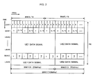
- FIG. 2 is a diagram schematically showing an example of a method for multiplexing reference signals according to a first exemplary embodiment of the present invention.
- the frame structure shown in FIG. 1A is used, in which one frame (sub-frame) includes long blocks LB#1 to LB#6, short blocks SB#1 and SB#2, and cyclic prefixes (CP), with the short block SB#1 being inserted between the long blocks LB#1 and LB#2, and the short block SB#2 being inserted between the long blocks LB#5 and LB#6.
- one frame includes long blocks LB#1 to LB#6, short blocks SB#1 and SB#2, and cyclic prefixes (CP), with the short block SB#1 being inserted between the long blocks LB#1 and LB#2, and the short block SB#2 being inserted between the long blocks LB#5 and LB#6.
- CP cyclic prefixes
- L1/L2 control signals are allocated the long block LB#1
- reference signals also referred to as pilot signals
- data signals are allocated the long blocks LB#2 to LB#6.
- a time interval between the short blocks SB#1 and SB#2, which reference signals are allocated, is set so that fading variance in each channel during data transmission can be followed. Note that in FIG. 2, illustration of the cyclic prefixes (CP) shown in FIG. 1 A is omitted.
- the bandwidth of a subcarrier in each short block SB is twice as wide as that in each long block LB.
- the number of reference signals to be multiplexed by distributed FDM is set so that a sufficient number of reference signal sequences will be provided. It is desirable that the number of reference signals to be multiplexed by distributed FDM be set to two.
- a resource allocated for any one of an L1/L2 control signal, reference signal, and data signal of a certain user equipment will be referred to as a "resource block,” and a resource allocated in the frequency domain in one short block will be referred to as a "frequency resource.”
- a resource allocated in the frequency domain in one short block will be referred to as a "frequency resource.”
- the set of subcarriers allocated to the UE 1a in four frequency blocks is a "frequency resource.”
- an L1/L2 control signal, reference signal, and data signal are multiplexed in the time direction in each frame.
- Resources allocated for the L1/L2 control signal, reference signal, and data signal in one frame FR will be referred to as a control resource, reference resource, and data resource, respectively.
- an L1/L2 control signal in this example is an uplink control signal regarding a downlink data signal, which is called "data non-associated control signalling," and contains ACK/NACK indicative of whether or not a downlink CQI or a downlink packet has been fully received, and the like.
- a reference signal for demodulation/detection (hereinafter, also referred to as a demodulation/detection reference signal) is multiplexed in any one or both of the short blocks SB#1 and SB#2. If a corresponding transmission signal is spread over a sub-frame in time domain and variances in channel quality in time domain cannot be ignored within the period of a sub-frame (for example, like data signals of user equipments UE1 and UE2 in FIG. 2), then the demodulation/detection reference signal is multiplexed in both the short blocks SB#1 and SB#2, across the entire transmission bandwidth of this transmission signal.
- the demodulation/detection reference signal is multiplexed in only one of the short blocks SB#1 and SB#2. In FIG. 2, the demodulation/detection reference signal is multiplexed in the short block SB#1.
- a demodulation/detection reference signal is also transmitted. Therefore, to a user equipment to which a control resource is allocated in a frequency block, a reference resource is also allocated in the same frequency block. To a user equipment to which a data resource is allocated in a frequency block, a reference resource is also allocated in the same frequency block.
- frequency bandwidths BW1 and BW2 for example, 6.25 MHz and 3.75 MHz, respectively
- a distributed demodulation/detection reference signal of the mobile station UE1 is multiplexed in both of the short blocks SB#1 and SB#2 within the same frequency bandwidth BW1
- a distributed demodulation/detection reference signal of the mobile station UE2 is allocated both of the short blocks SB#1 and SB#2 within the same frequency bandwidth BW2.
- the numerals in the short blocks SB#1 and SB#2 represent the mobile stations' numbers (the same holds true with the long block LB#1.) Moreover, it is assumed that mobile stations UE3 and UE4 are allocated the same frequency bandwidth BW3/4 in the long block LB#1 for L1/L2 control signals, which are multiplexed by distributed FDM within the same bandwidth BW3/4. In this case, corresponding distributed demodulation/detection reference signals of the mobile stations UE3 and UE4 are allocated a short block that is closer to the long block LB#1 (here, the short block SB#1), within the same bandwidth BW3/4.
- the L1/L2 control signals of the mobile stations UE3 and UE4 are multiplexed by distributed FDM within a same bandwidth BW3/4, and, if the maximum number of signals that can be multiplexed by CDM in the short block SB#1 is not smaller than two, the distributed reference signals of the mobile stations UE3 and UE4 are multiplexed by CDM in the short block SB#1 (denoted by "3/4" in FIG. 2), within the same frequency bandwidth BW3/4.
- L1/L2 control signals of mobile stations UE5 and UE6 are multiplexed by distributed FDM within a same bandwidth BW5/6, and, if the maximum number of signals that can be multiplexed by CDM in the short block SB#1 is not smaller than two, corresponding distributed reference signals of the mobile stations UE5 and UE6 are multiplexed by CDM in the short block SB#1 (denoted by "5/6" in FIG. 2), in a distributed manner within the same frequency bandwidth BW5/6.
- a reference signal for channel quality (CQI) estimation (hereinafter, also referred to as a CQI estimation reference signal), which is transmitted independently of a demodulation/detection reference signal, is multiplexed in any one of three types of frequency resources in a short block, which are generalized as follows:
- a frequency resource that is not and will not be allocated for a demodulation/detection reference signal is defined as a frequency resource that is unoccupied in a short block and will be allocated neither for a reference signal for demodulation/detection of a data signal nor for a reference signal for demodulation/detection of a L1/L2 control signal.
- an unoccupied resource is a frequency resource with a 10-MHz frequency bandwidth, labelled "7" in FIG. 2.
- this unoccupied frequency resource applying to the above-described item (1), is allocated to a mobile station UE7 for CQI estimation, as shown in FIG. 2. Thereafter, it is checked whether or not there is an unoccupied frequency resource applying to the above-described item (2), and then a frequency resource applying to the above-described item (3). If such a frequency resource is available, the resource is allocated for a CQI estimation reference signal.
- a frequency resource applying to the above-described item (1).
- demodulation/detection reference signals are multiplexed as described above in the section 1.2.
- a reference signal for estimation of the channel quality of the mobile station UE7 should be allocated a short block.
- an unoccupied frequency resource is present in the short block SB#2, which is subsequent to the short block SB#1. This is because the possibility of the presence of an unoccupied frequency resource applying to the above-described item (1), "a frequency resource that is not and will not be allocated for a demodulation/detection reference signal," or an unoccupied frequency resource applying to the above-described item (2), "a frequency resource that can be allocated for a demodulation/detection reference signal and is not currently occupied by a demodulation/detection reference signal,” is higher in the short block SB#2 than in the short block SB#1.
- frequency resources are allocated only to the mobile stations UE1 and UE2 for the reference signals for demodulation/detection of their data signals, and an unoccupied frequency bandwidth is present that is not allocated for at least one of a reference signal for demodulation/detection of a data signal and a reference signal for demodulation/detection of an L1/L2 control signal. Accordingly, if this unoccupied frequency bandwidth is not smaller than the required bandwidth, a CQI estimation reference signal of the mobile station UE7 can be allocated this unoccupied frequency bandwidth. For example, if the unoccupied frequency bandwidth in the short block SB#2 is 10 MHz as shown in FIG. 2, a CQI estimation reference signal of the mobile station UE7 can be allocated the unoccupied frequency bandwidth in the short block SB#2.
- the short block SB#1 it is also possible to check the presence of an unoccupied frequency resource first in the short block SB#1.
- the bandwidth BW7 which is the CQI estimation range for the mobile station UE7, is 6.25 MHz, the same as the frequency bandwidth BW 1 for the mobile station UE1. If an unoccupied frequency resource as required is not present in the short block SB#2, then it is checked whether or not an unoccupied frequency resource is present in the short block SB#1. Although the whole short block SB#1 is occupied by the reference signals for demodulation/detection of data and control signals, the transmission bandwidth BW1 of the reference signal for demodulation/detection of the data signal matches with the transmission bandwidth BW7 required by the mobile station UE7, and the maximum number of signals that can be multiplexed by CDM in the short block SB#1 is not smaller than two.
- a CQI estimation reference signal of the mobile station UE7 is allocated a frequency resource by being multiplexed by CDM with the demodulation/detection reference signal of the mobile station UE1 in the short block SB#1.
- bandwidths BW7 and BW8, which are the CQI estimation ranges for two mobile stations UE7 and UE8 respectively, are each 10 MHz.
- frequency resources are allocated only to the mobile stations UE1 and UE2 for the reference signals for demodulation/detection of their data signals, and an unoccupied frequency bandwidth of 10 MHz is present that is not allocated for at least one of a reference signal for demodulation/detection of a data signal and a reference signal for demodulation/detection of an L1/L2 control signal.
- CQI estimation reference signals of the mobile stations UE7 and UE8 can be allocated this unoccupied frequency bandwidth by CDM.
- the present invention it is possible to set a small number of reference signals that are multiplexed by distributed FDM in a same short block, within a frequency band in which the reference signals are to be transmitted. For example, if the number of reference signals that are multiplexed by distributed FDM is set to two, then the sequence length of a reference signal is half the length when a reference signal occupies the entire frequency in the same band. Accordingly, it is possible to set a large number of reference signal sequences that can be secured.
- a reference signal for demodulation/detection of an L1/L2 control signal is allocated the short block SB#1, which is closer in the time direction to the long block LB#1 which the L1/L2 control signal is allocated. Therefore, channel estimation used for demodulation of the L1/L2 control signal can be performed with high accuracy.
- the independent reference signal for CQI estimation cannot be allocated the short block SB#1
- the independent reference signal is allocated the short block SB#2, which is closer to the next frame on the time axis. Therefore, the measurement of the channel quality of a mobile station UE in question is less susceptible to a processing delay.
- FIG. 3 is a diagram schematically showing an example of a method for multiplexing reference signals according to a second exemplary embodiment of the present invention.
- independent reference signals for CQI estimation have two types of frequency bandwidths.
- resource allocation in a first frame FR1 is the same as in FIG. 2. That is, an independent reference signal of the mobile station UE7 is allocated a short block SB#2 in the frame FR1, as in FIG. 2.
- the frequency bandwidth thereof (2.5 MHz) matches neither with transmission bandwidths BW1 and BW2 of reference signals for demodulation/detection of data signals of mobile station UE1 and UE2, nor with the transmission bandwidth BW7 of the independent reference signal of the mobile station UE7. Accordingly, since the independent reference signals of the mobile stations UE8 to UE11 do not meet the condition A described earlier, these independent reference signals cannot be allocated either of the short blocks SB#1 and SB#2.
- channel quality does not need to be consecutively measured for the mobile station UE7, to which the short block SB#2 is allocated in the frame FR1. Accordingly, in this case, it is possible to allocate a short block SB#2 in the next frame FR2, for the independent reference signals of the mobile stations UE8 to UE11. A short block SB#1 in the frame FR2 cannot be allocated because the condition A is not met.
- channel quality does not need to be measured in every frame. Nevertheless, as a CQI measurement period becomes shorter, accurate scheduling for mobile stations moving faster can be achieved, although the overhead is increased. Conversely, as a CQI measurement period becomes longer, accurate scheduling for mobile stations moving faster becomes difficult to achieve, but the overhead can be reduced. Therefore, it is desirable to determine the CQI measurement period with consideration given to what moving speed of mobile stations the optimization is based upon.
- a coherent time is a supposed length of time during which channel variance of a mobile station can be considered constant
- the effects of channel-dependent scheduling cannot be obtained as expected when the CQI measurement period is longer than the coherent time. Therefore, it is desirable to set the CQI measurement period to be equal to or smaller than the supposed coherent time.
- resources can be allocated even to a plurality of independent reference signals with different transmission bandwidths, by multiplexing the independent reference signals in the time direction.
- the sequence length of a reference signal is half the length when a reference signal occupies the entire frequency in the same band. Accordingly, it is possible to set a large number of reference signal sequences that can be secured.
- a reference signal for demodulation/detection of an L1/L2 control signal is allocated the short block SB#1, which is closer in the time direction to the long block LB#1 which the L1/L2 control signal is allocated. Therefore, channel estimation used for demodulation of the L1/L2 control signal can be performed with high accuracy.
- the independent reference signal for CQI estimation cannot be allocated the short block SB#1
- the independent reference signal is allocated the short block SB#2, which is closer to the next frame on the time axis. Therefore, the measurement of the channel quality of a mobile station UE in question is less susceptible to a processing delay.
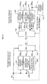
- FIG. 4 is a block diagram showing a fundamental configuration of a base station in a radio communications system according to an example of the present invention.
- a base station 10 accommodates a plurality of mobile stations UE1, UE2, ... .
- Major components of the base station 10 related to the present example include a radio transceiver (Tx/Rx) 101, a reception processing section R, a control section 106, a resource management section 107, and a transmission processing section T.
- Tx/Rx radio transceiver
- the radio transceiver (Tx/Rx) 101 transmits and receives radio signals to/from the plurality of mobile stations UE through respective channels, by using the frequency/time-multiplexing structure as shown in any one of FIGS. 2 and 3.
- the radio transceiver 101 outputs a multiplexed reception signal S RX from the plurality of mobile stations UE to the reception processing section R, and also converts a multiplexed transmission signal S TX inputted from the transmission processing section T into a radio transmission signal.
- the reception processing section R includes a signal demultiplexing section 102, a data signal reproduction section 103, an L1/L2 control signal reproduction section 104, and a channel quality measurement section 105.
- the signal demultiplexing section 102 removes cyclic prefixes (CP) and demultiplexes, in time domain, data signals in the long blocks LB#2 to LB#6, L1/L2 control signals in the long block LB#1, and reference signals in the short blocks SB#1 and SB#2, from the reception signal S RX multiplexed by TDM as shown in FIG. 2.
- CP cyclic prefixes
- the signal demultiplexing section 102 identifies a resource block or resource blocks allocated to each mobile station UE, and demultiplexes the multiplexed reception signal S Rx received from the mobile stations UEs back to reception data signals S RDATA , reception L1/L2 control signals S RCTL , and three types of reference signals: reference signal S DREF for demodulation/detection of the reception data; reference signal S CREF for demodulation/detection of the reception L1/L2 control signal; and independent reference signal S IREF for CQI estimation.
- the data signal reproduction section 103 inputs the reception data signal S RDATA and corresponding demodulation/detection reference signal S DREF of each mobile station UE, demodulates/detects reception data S DATA , and outputs the reception data S DATA to the control section 106.
- the L1/L2 control signal reproduction section 104 inputs the reception L1/L2 control signal S RCTL and corresponding demodulation/detection reference signal S CREF of each mobile station UE, demodulates/detects an L1/L2 control signal S CTL , and outputs the L1/L2 control signal S CTL to the control section 106.
- the channel quality measurement section 105 inputs the three types of reference signals (reference signal S DREF for demodulation/detection of the reception data, reference signal S CREF for demodulation/detection of the reception L1/L2 control signal, and independent reference signal S IREF for CQI estimation), measures uplink channel quality S CQI_U of each mobile station UE by using a reference signal sequence maintained by itself, and outputs the measured uplink channel quality S CQI_U to the control section 106 and resource management section 107.
- reference signal S DREF for demodulation/detection of the reception data
- reference signal S CREF for demodulation/detection of the reception L1/L2 control signal
- independent reference signal S IREF independent reference signal
- the resource management section 107 inputs the respective uplink channel qualities S CQI_U of the mobile stations UE and compares them, thereby generating uplink resource allocation information S RAL_U indicating which resource blocks are allocated to which mobile stations UE, with respect to each of the data signal, L1/L2 control signal, and reference signals.
- the signal demultiplexing section 102 performs signal demultiplexing in accordance with this uplink resource allocation information S RAL_U .
- the transmission processing section T includes a data signal generation section 108, an L1/L2 control signal generation section 109, a reference signal generation section 110, and a signal multiplexing section 111.
- the data signal generation section 108 generates a downlink data signal S TDATA for a mobile station UE to which downlink data should be transmitted, in accordance with downlink resource allocation information S RAL_D inputted from the resource management section 107, and outputs the generated downlink data signal S TDATA to the signal multiplexing section 111.
- the L1/L2 control signal generation section 109 generates a downlink L1/L2 control signal S TCTL for a mobile station UE to which a downlink L1/L2 control signal should be transmitted, in accordance with the downlink resource allocation information S RAL_D inputted from the resource management section 107, and outputs the generated downlink L1/L2 control signal S TCTL , to the signal multiplexing section 111.
- the reference signal generation section 110 generates a reference signal S TREF in accordance with the downlink resource allocation information S RAL_D received as input from the resource management section 107 and outputs the generated reference signal S TREF to the signal multiplexing section 111.
- the reference signal generation section 110 in accordance with the downlink resource allocation information S RAL_D , the reference signal generation section 110 generates a demodulation/detection reference signal for a mobile station UE to which a downlink data signal or downlink L1/L2 control signal is to be transmitted, and generates a CQI estimation reference signal for a mobile station UE which has made an entry for channel-dependent scheduling.
- the resource management section 107 inputs downlink channel qualities S CQI _ D respectively measured by the mobile stations UE and then generates the downlink resource allocation information S RAL_D , which will be described later.
- the signal multiplexing section 111 multiplexes in FDM and/or TDM the thus generated downlink data signals S TDATA , downlink L1/L2 control signals S TCTL , and reference signals S TREF for the mobile stations UE, in accordance with the downlink resource allocation information S RAL_D , thereby generating a transmission signal S TX and transmitting it from the radio transceiver 101.
- the uplink resource allocation information S RAL_U and downlink resource allocation information S RAL_D generated by the resource management section 107 are contained in an L1/L2 control signal generated by the L1/L2 control signal generation section 109 and are transmitted to each mobile station UE, under the control of the control section 106.
- Each mobile station UE receives the uplink resource allocation information S RAL_U and downlink resource allocation information S RAL_D and determines resource blocks to use respectively for uplink and downlink communications with the base station 10 in accordance with the received uplink resource allocation information S RAL_U and downlink resource allocation information S RAL_D .
- control section 106 controls the entire operation of the base station 10.
- the functions of the resource management section 107 can also be implemented by executing a resource management program on a program-controlled processor, or a computer.
- FIG. 5 is a block diagram showing a configuration of a mobile station in the radio communications system according to the present example. Since mobile stations do not perform resource management, resources for the mobile station itself to use in transmission and reception are determined in accordance with the uplink resource allocation information S RAL_U and downlink resource allocation information S RAL_D received from the base station 10. Hereinafter, the configuration of a mobile station will be described briefly.
- a radio transceiver (Tx/Rx) 201 transmits and receives radio signals to/from the base station 10 through a designated channel.
- the reception processing section R includes a signal demultiplexing section 202, a data signal reproduction section 203, an L1/L2 control signal reproduction section 204, and a channel quality measurement section 205.
- the signal demultiplexing section 202 identifies a resource block or resource blocks allocated to the mobile station 20, in accordance with downlink resource allocation information S RAL_D designated by the control section 206, and demultiplexes a reception data signal S RDATA , a reception L1/L2 control signal S RCTL , and three types of reference signals: reference signal S DREF for demodulation/detection of the reception data; reference signal S CREF for demodulation/detection of the reception L1/L2 control signal; and independent reference signal S IREF for CQI estimation.
- the data signal reproduction section 203 inputs the reception data signal S RDATA and corresponding demodulation/detection reference signal S DREF , demodulates/detects reception data S DATA , and outputs the reception data S DATA to the control section 206.
- the L1/L2 control signal reproduction section 204 inputs the reception L1/L2 control signal S RCTL and corresponding demodulation/detection reference signal S CREF , demodulates/detects an L1/L2 control signal S CTL , and outputs the L1/L2 control signal S CTL to the control section 206.
- the channel quality measurement section 205 inputs the three types of reference signals (reference signal S DREF for demodulation/detection of the reception data, reference signal S CREF for demodulation/detection of the reception L1/L2 control signal, and independent reference signal S IREF for CQI estimation), measures downlink channel quality S CQI_D of the mobile station 20 itself, and outputs the measured downlink channel quality S CQI_D to the control section 206.
- reference signal S DREF for demodulation/detection of the reception data
- reference signal S CREF for demodulation/detection of the reception L1/L2 control signal
- independent reference signal S IREF for CQI estimation
- control section 206 controls the signal demultiplexing section 202 in accordance with the downlink resource allocation information S RAL_D as described above, and controls the transmission processing section T in accordance with the uplink resource allocation information S RAL_U as described below.
- the transmission processing section T includes a data signal generation section 207, an L1/L2 control signal generation section 208, a reference signal generation section 209, and a signal multiplexing section 210.
- the data signal generation section 207 when transmitting uplink data, generates an uplink data signal S TDATA in accordance with the uplink resource allocation information S RAL_U inputted from the control section 206 and outputs the generated uplink data signal S TDATA to the signal multiplexing section 210.
- the L1/L2 control signal generation section 208 when transmitting an uplink L1/L2 control signal, generates an uplink L1/L2 control signal S TCTL in accordance with the uplink resource allocation information S RAL_U and outputs the generated uplink L1/L2 control signal S TCTL to the signal multiplexing section 210.
- the reference signal generation section 209 generates a reference signal S REF in accordance with the uplink resource allocation information S RAL_U and outputs the generated reference signal S TREF to the signal multiplexing section 210.
- the reference signal generation section 209 in accordance with the uplink resource allocation information S RAL_U , the reference signal generation section 209 generates a demodulation/detection reference signal when the mobile station 20 has an uplink data signal or uplink L1/L2 control signal to transmit, and generates a CQI estimation reference signal when the mobile station 20 has made an entry for channel-dependent scheduling.
- the signal multiplexing section 210 multiplexes the thus generated uplink data signal S TDATA , uplink L1/L2 control signal S TCTL , and/or reference signal S TREF in the resource blocks designated by the uplink resource allocation information S RAL_U , thereby generating a transmission signal S TX and transmitting it from the radio transceiver 201 to the base station 10.
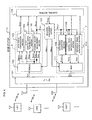
- FIG. 6 is a schematic diagram showing system architecture for describing operations in the radio communications system according to the present example.
- a transmitting device T corresponds to the mobile station 20 shown in FIG. 5
- a receiving device R corresponds to the base station 10 shown in FIG. 4.
- Blocks having the same functions as those in FIGS. 4 and 5 are denoted by the same reference numerals as those in FIGS. 4 and 5, and the description thereof will be omitted.
- operations of the transmitting device T and receiving device R will be described with reference to the block diagram of FIG. 6 and flowcharts of FIGS. 7 and 8. Note that in FIG. 6, a signal is transmitted from the transmitting device T to the receiving device R, and therefore uplink resource allocation information S RAL_U and downlink resource allocation information S RAL_D are simply referred to as "resource allocation information S RAL .”
- FIG. 7 is a flowchart showing an operation of the mobile station according to the present example.
- the control section 206 of the mobile station sets resource allocation information S RAL received from the base station 10 (step S301), and then determines whether or not a resource for a data signal is allocated (step S302). If a resource for a data signal is allocated (YES in step S302), the control section 206 controls the data signal generation section 207 and reference signal generation section 209 to generate a data signal S DATA and a reference signal S REF (step 5303). If a resource for a data signal is not allocated (NO in step S302), the control section 206 does not carry out the step S303.
- the control section 206 determines whether or not a resource for an L1/L2 control signal is allocated (step S304). If a resource for an L1/L2 control signal is allocated (YES in step S304), the control section 206 controls the L1/L2 control signal generation section 208 and reference signal generation section 209 to generate an L1/L2 control signal S CTL and a reference signal S REF (step S305). If a resource for an L1/L2 control signal is not allocated (NO in step S304), the control section 206 does not carry out the step S305.
- control section 206 determines whether or not a resource for a CQI estimation reference signal (independent reference signal) is allocated (step S306). If a resource for an independent reference signal is allocated (YES in step S306), the control section 206 controls the reference signal generation section 209 to generate an independent reference signal S REF (step S307). If a resource for an independent reference signal is not allocated (NO in step S306), the control section 206 does not carry out the step S307.
- the signals thus generated by the data signal generation section 207, L1/L2 control signal generation section 208, and/or reference signal generation section 209 are multiplexed by FDM and/or TDM in accordance with the resource allocation information S RAL as described already, whereby a transmission signal S TX is generated (step S308).
- the transmission signal S TX is transmitted to the base station 10 via the radio transceiver 201 (step S309).
- FIG. 8 is a flowchart showing an operation of the base station according to the present example.
- the control section 106 of the base station 10 controls the signal demultiplexing section 102, using resource allocation information S RAL .
- the signal demultiplexing section 102 identifies a resource block or resource blocks allocated to each mobile station UE and demultiplexes a reception data signal S RDATA , a reception L1/L2 control signal S RCTL , and three types of reference signals (reference signal S DREF for demodulation/detection of the reception data, reference signal S CREF for demodulation/detection of the reception L1/L2 control signal, and independent reference signal S IREF for CQI estimation) of each mobile station UE (step S402).
- reference signal S DREF for demodulation/detection of the reception data
- reference signal S CREF for demodulation/detection of the reception L1/L2 control signal
- independent reference signal S IREF for CQI estimation
- the control section 106 controls the resource management section 107, which then determines, with respect to each mobile station UE, whether or not a resource for a data signal is allocated (step S403). If a resource for a data signal is allocated to the mobile station UE (YES in step S403), the control section 106 controls the data signal reproduction section 103 to have it reproduce an uplink data signal S DATA sent from the mobile station UE in question, and controls the channel quality measurement section 105 to have it measure channel quality S CQI of the mobile station UE in question from the reference signal S DREF for demodulation/detection of that reception data (step S404). For a mobile station UE to which a resource for a data signal is not allocated (NO in step S403), the control section 106 does not carry out the step S404.
- the control section 106 controls the resource management section 107, which then determines, with respect to each mobile station UE, whether or not a resource for an L1/L2 control signal is allocated (step S405). If a resource for an L1/L2 control signal is allocated to the mobile station UE (YES in step S405), the control section 106 controls the L1/L2 control signal reproduction section 104 to have it reproduce an uplink L1/L2 control signal S CTL sent from the mobile station UE in question, and controls the channel quality measurement section 105 to have it measure channel quality S CQI of the mobile station UE in question from a reference signal S CREF for demodulation/detection of that L1/L2 control signal (step S406). For a mobile station UE to which a resource for an L1/L2 control signal is not allocated (NO in step S403), the control section 106 does not carry out the step S406.
- the control section 106 determines whether or not a resource for a CQI estimation reference signal (independent reference signal) is allocated (step S407). If a resource for an independent reference signal is allocated (YES in step S407), the control section 106 controls the channel quality measurement section 105 to have it measure channel quality S CQI of the mobile station UE in question from the independent reference signal S IREF (step S408). For a mobile station UE to which a resource for an independent reference signal is not allocated (NO in step S407), the control section 106 does not carry out the step S408.
- control section 106 controls the resource management section 107 to determine which resources will be allocated to which mobile stations UE (that is, resource allocation information S RAL ), based on the channel quality S CQI of each mobile station UE inputted from the channel quality measurement section 105 (step S409). Then, as described already, corresponding resource allocation information S RAL is notified to each mobile station UE (step S410).
- FIG. 9A is a diagram of a frame structure showing the resource allocation shown in FIG. 2.
- FIG. 9B is a sequence diagram showing allocation of a resource for a reference signal to a mobile station transmitting data.
- FIG. 9C is a sequence diagram showing allocation of a resource for a reference signal to a mobile station transmitting an L1/L2 control signal.
- FIG. 9D is a sequence diagram showing allocation of a resource for a reference signal to a mobile station transmitting an independent reference signal.
- a mobile station UE1 has transmitted a CQI estimation reference signal S REF using an unoccupied frequency resource in a short block SB#1 or SB#2 in accordance with resource allocation information S RAL eceived from the base station 10, as described in any one of the first to third examples in the section 1.3.
- the base station 10 measures channel quality S CQI of the mobile station UE1 from this CQI estimation reference signal S IREF .
- the base station 10 determines to allocate a resource for a data signal to the mobile station UE1 as shown in FIG.
- the base station 10 notifies the mobile station UE1 of resource allocation information S RAL indicative of a transmission frequency bandwidth to be allocated and corresponding frequency resources in short blocks SB#1 and SB#2.
- the mobile station UE1 generates uplink data S DATA and a corresponding demodulation/detection reference signal S REF , multiplexes in distributed-FDM and TDM manner the demodulation/detection reference signal S REF in each of the short blocks SB#1 and SB#2 as shown in FIG. 9A, and then transmits the multiplexed signal to the base station 10.
- a mobile station UE3 has transmitted a CQI estimation reference signal S IREF by using an unoccupied frequency resource in a short block SB#1 or SB#2 in accordance with resource allocation information S RAL received from the base station 10, as described in any one of the first to third examples in the section 1.3.
- the base station 10 measures channel quality S CQI of the mobile station UE3 from this CQI estimation reference signal S IREF .
- the base station 10 determines to allocate a resource for an L1/L2 control signal to the mobile station UE3 as shown in FIG.
- the base station 10 notifies the mobile station UE3 of resource allocation information S RAL indicative of a transmission frequency bandwidth to be allocated and a corresponding frequency resource in a short block SB#1.
- the mobile station UE3 generates an uplink L1/L2 control signal S CTL and a corresponding demodulation/detection reference signal S REF , multiplexes in distributed-FDM and TDM manner the demodulation/detection reference signal S REF in the short block SB#1 as shown in FIG. 9A, and then transmits the multiplexed signal to the base station 10.
- a mobile station UE7 has sent a request for data transmission to the base station 10 and has made an entry for channel-dependent scheduling with the resource management section 107 of the base station 10.
- the mobile station UE7 transmits a CQI estimation reference signal S IREF by using an unoccupied frequency resource in a short block SB#1 or SB#2 in accordance with resource allocation information S RAL received from the base station 10, as described in any one of the first to third examples in the section 1.3.
- the base station 10 notifies the mobile station UE7 of resource allocation information S RAL indicative of the entire frequency bandwidth of a short block SB#2 as shown in FIG. 9A.
- the mobile station UE7 In accordance with this resource allocation information S RAL , the mobile station UE7 generates a CQI estimation reference signal S IREF , distributed-frequency-division-multiplexes and time-division-multiplexes the CQI estimation reference signal S IREF in the short block SB#2, and then transmits the multiplex signal to the base station 10.
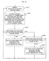
- FIG. 10 is a flowchart showing resource allocation control to allocate a resource to a CQI estimation reference signal according to the present example.
- the operation of allocating resources for demodulation/detection and CQI estimation reference signals in the short blocks SB#1 and SB#2 is repeated in every frame (S501).
- S501 a frame
- a frequency resource with a transmission bandwidth required for a reference signal used in that communication is allocated to this mobile station (S502).
- a frequency resource in both the short blocks SB#1 and SB#2 is allocated to a reference signal for demodulation/detection of the data
- a frequency resource in the short block SB#1 is allocated to a reference signal for demodulation/detection of the L1/L2 control signal.
- step S503 it is checked whether or not an unoccupied frequency resource is present in the short block SB#2 (step S503).
- the checking of the presence or absence of an unoccupied frequency resource can be carried out as described already in the section 1.3.
- the steps are as follows:
- this frequency resource in the short block SB#2 is allocated to, depending on the bandwidth of the frequency resource, one or a plurality of the mobile stations waiting for channel-dependent scheduling, for their CQI estimation reference signals (step S504).
- step S503 If such a frequency resource is not present in the short block SB#2 (NO in step S503), it is next checked whether or not an unoccupied frequency resource is present in the short block SB#1 (step S505).
- the checking of the presence or absence of an unoccupied frequency resource is similarly performed as in the above-described procedure.
- this frequency resource in the short block SB#1 is allocated to, depending on the bandwidth of the frequency resource, one or a plurality of the mobile stations waiting for channel-dependent scheduling, for their CQI estimation reference signals (step S506). If such a frequency resource is not present in the short block SB#1 either (NO in step S505), similar processing is repeated in the next frame.
- step S505 may also be subsequently performed, in which it is checked whether or not an unoccupied frequency resource is present in the short block SB#1.
- a reference signal for demodulation/detection of an L1/L2 control signal is allocated a short block SB#1, which is closer in the time direction to a long block LB#1 which the L1/L2 control signal is allocated. Accordingly, it is possible to perform channel estimation used for demodulation of the L1/L2 control signal, with high accuracy.
- a CQI estimation reference signal when it cannot be allocated a short block SB#1, is allocated a short block SB#2, which is closer to the next frame on the time axis. Accordingly, the measurement of channel quality is less susceptible to a processing delay.
- the restrictions as to the number of reference signal sequences that can be secured can be diminished to sufficiently low level, while the accuracy with which a data signal or L1/L2 control signal is demodulated and the accuracy with which channel quality is measured are kept at high level.
- the present invention can be applied to radio communications systems and, more particularly, to mobile communications systems employing a scheme of multiplexing reference signals (pilot signals) with data and control signals, as well as to base and mobile stations in such a system, and operation programs for the base and mobile stations.
- reference signals pilot signals
- the present invention provides a resource allocation method and reference signal multiplexing method that can diminish the restrictions as to the number of reference signal sequences that can be secured, and that can prevent a reduction in the number of reference signals multiplexed, as well as a radio communications system using the methods.
- the present invention also provides a resource allocation method and reference signal multiplexing method that enable reference signals with different transmission bandwidths to be efficiently allocated a limited frequency band, as well as a radio communications system using the methods.
- the present invention is based on findings such that the size of a resource allocated to a reference signal is changed depending on its use purpose and degree of importance. According to the present invention, high efficient multiplexing of reference signals and diminishing the restrictions as to the number of reference signal sequences can be achieved. For example, a reference signal for demodulation/detection of a data signal or an L1/L2 control signal is multiplexed by distributed FDM over the same bandwidth as the transmission bandwidth of the data signal or L1/L2 control signal. In addition, when a data signal is transmitted, a reference signal for demodulation/detection is multiplexed at a plurality of timings.
- a reference signal for demodulation/detection is multiplexed at a single timing closer in time to the L1/L2 control signal. It should be noted that hereinafter a reference signal for demodulation/detection of a data signal and a reference signal for demodulation/detection of a L1/L2 control signal are simply referred to as "a reference signal for demodulation/detection.”
- a reference signal for channel quality estimation may be multiplexed, independently of data signal or L1/L2 control signal, under the condition of timing and bandwidth allowing effective channel quality measurement within a channel quality measurement range.
- the number of reference signals to be multiplexed by distributed FDM at the same timing for each predetermined frequency block is previously set to a small number so that a sufficiently large number of reference signal sequences can be ensured.
- the respective reference signals are multiplexed by time and/or frequency division in a plurality of frequency resources in a plurality of reference signal timings, which will be described later as short blocks SB#1, SB#2. Resource allocation to reference signals at the plurality of reference signal timings will be described hereinafter.
- a resource allocating method in a radio communications system performing allocation of a reference resource includes: a) allocating a first resource to a reference signal which is used at least for either of demodulation and detection, wherein the first resource is at least part of the reference resource; and b) allocating a second resource to an independent reference signal which is used for processing other than demodulation and detection, wherein the second resource is at least part of the reference resource other than allocated to the reference signal which is used at least for either of demodulation and detection.
- a reference signal that is used at least for either of demodulation and detection will be referred to as "a demodulation/detection reference signal.” If variations in the channel quality of a corresponding transmission signal within a frame in time domain are not negligible, then the demodulation/detection reference signal is multiplexed by time division at a plurality of reference signal timings over the entire transmission bandwidth of the transmission signal. If variations in the channel quality of a corresponding transmission signal within a frame in time domain are negligible, then the demodulation/detection reference signal is multiplexed by time division at any one of the plurality of reference signal timings.
- a channel-quality estimation reference signal which is transmitted independently of demodulation/detection reference signals is multiplexed at one or more timing of the plurality of reference signal timings in one of the following resources:
- a reference signal which is transmitted independently of the presence or absence of a data signal and an L1/L2 control signal, or an independent reference signal is allocated a resource in which at least one of the demodulation/detection reference signals for the data signal and the L1/L2 control signal is not transmitted at the same timing within its transmission band.
- the demodulation/detection reference signals for the data signal is allocated a plurality of reference signal resources which are closer in time axis to a resource allocated to the data signal
- the demodulation/detection reference signals for the L1/L2 control signal is allocated a single reference signal resource which is closer in time axis to a resource allocated to the L1/L2 control signal
- an independent reference signal is allocated a resource in which at least one of the demodulation/detection reference signals for the data signal and the L1/L2 control signal is not transmitted at the same timing within its transmission band.
- the demodulation/detection reference signals for the data signal, the demodulation/detection reference signals for the L1/L2 control signal and the independent reference signal are multiplexed in frequency-division and/or time-division manner.
- reference signals are multiplexed in frequency-division and/or time-division depending on the usage purpose and importance of the reference signals, whereby a reduction can be achieved in the number of reference signals that are multiplexed by distributed FDM at the same timing in the transmission band of the reference signals.
- a reduction can be achieved in the number of reference signals that are multiplexed by distributed FDM at the same timing in the transmission band of the reference signals.
- an increase can be achieved in the number of reference signal sequences that can be secured. That is, it is possible to sufficiently diminish the restrictions as to the number of reference signal sequences that can be secured.
Landscapes
- Engineering & Computer Science (AREA)
- Signal Processing (AREA)
- Computer Networks & Wireless Communication (AREA)
- Quality & Reliability (AREA)
- Mobile Radio Communication Systems (AREA)
- Time-Division Multiplex Systems (AREA)
Applications Claiming Priority (1)
| Application Number | Priority Date | Filing Date | Title |
|---|---|---|---|
| JP2006225932A JP5077525B2 (ja) | 2006-08-22 | 2006-08-22 | 無線通信システムにおけるリファレンス信号多重方法および無線通信装置 |
Publications (3)
| Publication Number | Publication Date |
|---|---|
| EP1892911A2 true EP1892911A2 (de) | 2008-02-27 |
| EP1892911A8 EP1892911A8 (de) | 2008-04-16 |
| EP1892911A3 EP1892911A3 (de) | 2011-08-10 |
Family
ID=38938288
Family Applications (1)
| Application Number | Title | Priority Date | Filing Date |
|---|---|---|---|
| EP20070075710 Ceased EP1892911A3 (de) | 2006-08-22 | 2007-08-22 | Referenzsignalmultiplexierung und Ressourcenzuweisung |
Country Status (5)
| Country | Link |
|---|---|
| US (2) | US8594039B2 (de) |
| EP (1) | EP1892911A3 (de) |
| JP (1) | JP5077525B2 (de) |
| KR (1) | KR100944019B1 (de) |
| CN (1) | CN101132637B (de) |
Cited By (1)
| Publication number | Priority date | Publication date | Assignee | Title |
|---|---|---|---|---|
| EP2096896A3 (de) * | 2008-02-29 | 2011-06-22 | Fujitsu Limited | Kommunikationsvorrichtung und Zuweisungsbestimmungsverfahren |
Families Citing this family (36)
| Publication number | Priority date | Publication date | Assignee | Title |
|---|---|---|---|---|
| JP5077525B2 (ja) | 2006-08-22 | 2012-11-21 | 日本電気株式会社 | 無線通信システムにおけるリファレンス信号多重方法および無線通信装置 |
| JP4940867B2 (ja) | 2006-09-29 | 2012-05-30 | 日本電気株式会社 | 移動通信システムにおける制御信号およびリファレンス信号の多重方法、リソース割当方法および基地局 |
| JP4795190B2 (ja) * | 2006-10-03 | 2011-10-19 | 株式会社エヌ・ティ・ティ・ドコモ | 移動局装置及び基地局装置 |
| EP3393066B1 (de) | 2006-11-01 | 2021-12-01 | LG Electronics Inc. | Verfahren und vorrichtung zur zuweisung von piloten |
| EP3432504B1 (de) * | 2007-10-30 | 2021-06-23 | Nokia Technologies Oy | Verfahren, vorrichtungen, system und entsprechendes computerprogrammprodukt zur ressourcenzuweisung |
| JP5061892B2 (ja) * | 2007-12-28 | 2012-10-31 | 富士通株式会社 | 無線通信システムにおける信号多重方法、送信局及び受信局 |
| KR101314876B1 (ko) * | 2008-03-19 | 2013-10-04 | 닛본 덴끼 가부시끼가이샤 | 무선 통신 시스템, 무선 통신의 설정 방법, 기지국, 이동국 및 프로그램이 기록된 기록매체 |
| KR101228053B1 (ko) | 2008-06-20 | 2013-01-31 | 닛본 덴끼 가부시끼가이샤 | 리소스 할당 방법, 특정 방법, 기지국 및 이동국 |
| EP3358780B1 (de) | 2008-06-20 | 2021-11-10 | NEC Corporation | Ressourcenzuweisungsverfahren, basisstation und mobilstation |
| US8730933B2 (en) | 2008-09-18 | 2014-05-20 | Qualcomm Incorporated | Method and apparatus for multiplexing data and reference signal in a wireless communication system |
| US9402247B2 (en) | 2008-10-20 | 2016-07-26 | Interdigital Patent Holdings, Inc. | Uplink control information transmission methods for carrier aggregation |
| CN101729115A (zh) * | 2008-10-29 | 2010-06-09 | 华为技术有限公司 | 一种多天线发射方法、装置及系统 |
| BRPI1007424B1 (pt) | 2009-01-29 | 2021-02-23 | Sun Patent Trust | Aparelhos de transmissão e recepção configurados para transmitirsinal de referência, métodos de transmissão e recepção, e circuito integrado |
| KR101578083B1 (ko) * | 2009-03-03 | 2015-12-16 | 엘지전자 주식회사 | 다중안테나를 갖는 무선 통신 시스템에서 하향링크 기준 신호 전송 및 수신 방법 |
| CN102396248B (zh) * | 2009-03-16 | 2016-08-17 | 华为技术有限公司 | 传输信号的方法、通信装置及系统 |
| US8693429B2 (en) * | 2009-03-31 | 2014-04-08 | Qualcomm Incorporated | Methods and apparatus for generation and use of reference signals in a communications system |
| EP2418781B1 (de) * | 2009-04-10 | 2019-06-26 | LG Electronics Inc. | Verfahren zur übertragung eines downlink-referenzsignals und vorrichtung dafür |
| JP2011003970A (ja) * | 2009-06-16 | 2011-01-06 | Fujitsu Ltd | 受信装置、基地局装置及び同期タイミング検出方法 |
| CN105245312B (zh) * | 2009-06-19 | 2019-05-07 | 交互数字专利控股公司 | 在lte-a中用信号发送上行链路控制信息的方法及单元 |
| US8737335B2 (en) * | 2009-06-19 | 2014-05-27 | Kddi Corporation | Reference signal transmission scheduling device and reference signal transmission scheduling method |
| US9288026B2 (en) * | 2009-06-22 | 2016-03-15 | Qualcomm Incorporated | Transmission of reference signal on non-contiguous clusters of resources |
| US20120230238A1 (en) * | 2009-10-28 | 2012-09-13 | Lars Dalsgaard | Resource Setting Control for Transmission Using Contention Based Resources |
| KR101201946B1 (ko) | 2009-12-02 | 2012-11-16 | 한국과학기술원 | 무선 통신 시스템에서 네트워크 코딩을 이용한 제어 신호 및 데이터 신호 전달 장치 및 방법 |
| US8780826B2 (en) * | 2010-01-12 | 2014-07-15 | Qualcomm Incorporated | Continuous CDM/FDM structure for LTE uplink data |
| RU2012141562A (ru) | 2010-03-01 | 2014-04-10 | Интердиджитал Пэйтент Холдингз, Инк. | Способ и устройство для выполнения гибридных распределений восходящей линии связи по станции и по потоку |
| KR20120004869A (ko) * | 2010-07-07 | 2012-01-13 | 삼성전자주식회사 | 이동 통신 시스템에서 위치 기반 서비스 자원 할당 정보 송/수신 장치 및 방법 |
| JP5283669B2 (ja) * | 2010-08-10 | 2013-09-04 | 株式会社エヌ・ティ・ティ・ドコモ | 送信機、受信機及び無線通信方法 |
| EP2716101A1 (de) | 2011-05-23 | 2014-04-09 | InterDigital Patent Holdings, Inc. | Vorrichtung und verfahren für die übergabe einer drahtlosen sende-/empfangseinheit (wtru) einer gruppe |
| EP2742748A4 (de) * | 2011-08-12 | 2015-08-26 | Intel Corp | System und verfahren zur uplink-leistungssteuerung in einem drahtlosen kommunikationssystem |
| CN103428702B (zh) * | 2012-05-16 | 2016-12-28 | 普天信息技术研究院有限公司 | 一种控制小区间干扰的资源分配方法 |
| US20150139001A1 (en) * | 2013-11-20 | 2015-05-21 | Feng Xue | Method and apparatus for beam identification in multi-antenna systems |
| EP3381233B1 (de) | 2015-12-31 | 2020-09-09 | Nec Corporation | Verfahren und vorrichtungen zum senden und empfangen von uplink-informationen |
| CN107733609B (zh) | 2016-08-12 | 2023-10-13 | 华为技术有限公司 | 参考信号发送方法和参考信号发送装置 |
| CN109964437B (zh) * | 2017-02-08 | 2021-07-27 | 上海朗帛通信技术有限公司 | 一种用于动态调度的终端、基站中的方法和装置 |
| CN115038154B (zh) * | 2017-06-16 | 2025-08-15 | 中兴通讯股份有限公司 | 发送功率的确定方法及装置、终端 |
| US20250119250A1 (en) * | 2023-10-04 | 2025-04-10 | Qualcomm Incorporated | Reference signal designs for multiple access in uplink |
Citations (1)
| Publication number | Priority date | Publication date | Assignee | Title |
|---|---|---|---|---|
| JP2008053866A (ja) | 2006-08-22 | 2008-03-06 | Nec Corp | 無線通信システムにおけるリファレンス信号多重方法および無線通信装置 |
Family Cites Families (18)
| Publication number | Priority date | Publication date | Assignee | Title |
|---|---|---|---|---|
| US6748010B1 (en) | 1998-10-13 | 2004-06-08 | Qualcomm Incorporated | Combined searching and page monitoring using offline sample storage |
| KR100735374B1 (ko) * | 2001-08-30 | 2007-07-04 | 삼성전자주식회사 | 고속 순방향 패킷 접속 방식을 사용하는 통신 시스템에서고속 순방향 공통 채널 지시자를 송수신하는 장치 및 방법 |
| JP4157443B2 (ja) * | 2002-07-16 | 2008-10-01 | 松下電器産業株式会社 | 送信方法、送信信号生成方法およびそれを用いた送信装置 |
| KR100929072B1 (ko) * | 2002-09-06 | 2009-11-30 | 삼성전자주식회사 | 고속 순방향 패킷 접속방식을 적용하는 부호분할다중접속 통신시스템에서 채널 품질 식별 정보 송수신 장치 및 방법 |
| JP3748449B2 (ja) * | 2003-03-31 | 2006-02-22 | 株式会社東芝 | Ofdm受信装置 |
| EP1646163B1 (de) | 2003-08-06 | 2013-04-24 | Panasonic Corporation | Vorrichtung und verfahren zur funkkommunikation |
| KR20050091582A (ko) * | 2004-03-12 | 2005-09-15 | 삼성전자주식회사 | 광대역 무선 접속 시스템에서 하향 링크의 채널 품질 표시정보 전송 방법 |
| KR20050110409A (ko) * | 2004-05-18 | 2005-11-23 | 삼성전자주식회사 | 다중 안테나를 가진 통신 시스템의 채널 품질 지시자 채널전송 시스템 및 방법 |
| JP2006033778A (ja) * | 2004-06-17 | 2006-02-02 | Ntt Docomo Inc | 移動局、基地局、制御装置、移動通信システム及び移動通信方法 |
| JP2006168476A (ja) | 2004-12-14 | 2006-06-29 | Toyota Motor Corp | 車室内換気システム |
| EP1911173B1 (de) * | 2005-07-27 | 2018-09-12 | BlackBerry Limited | Pilotsignale für die frequenzmultiplex-mehrfachzugangskommunikation |
| US20070183386A1 (en) * | 2005-08-03 | 2007-08-09 | Texas Instruments Incorporated | Reference Signal Sequences and Multi-User Reference Signal Sequence Allocation |
| US20070171849A1 (en) * | 2006-01-03 | 2007-07-26 | Interdigital Technology Corporation | Scheduling channel quality indicator and acknowledgement/negative acknowledgement feedback |
| WO2007087602A2 (en) * | 2006-01-25 | 2007-08-02 | Texas Instruments Incorporated | Method and apparatus for increasing the number of orthogonal signals using block spreading |
| JP2009527187A (ja) * | 2006-04-28 | 2009-07-23 | ミツビシ・エレクトリック・リサーチ・ラボラトリーズ・インコーポレイテッド | 送信時間インターバルのグルーピングを使用してofdmシステムの基準信号を処理する方法及びシステム |
| US7701919B2 (en) * | 2006-05-01 | 2010-04-20 | Alcatel-Lucent Usa Inc. | Method of assigning uplink reference signals, and transmitter and receiver thereof |
| US8374161B2 (en) * | 2006-07-07 | 2013-02-12 | Qualcomm Incorporated | Method and apparatus for sending data and control information in a wireless communication system |
| US9143288B2 (en) * | 2006-07-24 | 2015-09-22 | Qualcomm Incorporated | Variable control channel for a wireless communication system |
-
2006
- 2006-08-22 JP JP2006225932A patent/JP5077525B2/ja not_active Expired - Fee Related
-
2007
- 2007-08-20 US US11/841,021 patent/US8594039B2/en active Active
- 2007-08-21 KR KR20070084112A patent/KR100944019B1/ko not_active Expired - Fee Related
- 2007-08-22 EP EP20070075710 patent/EP1892911A3/de not_active Ceased
- 2007-08-22 CN CN200710142548XA patent/CN101132637B/zh not_active Expired - Fee Related
-
2013
- 2013-01-02 US US13/732,800 patent/US20130121305A1/en not_active Abandoned
Patent Citations (1)
| Publication number | Priority date | Publication date | Assignee | Title |
|---|---|---|---|---|
| JP2008053866A (ja) | 2006-08-22 | 2008-03-06 | Nec Corp | 無線通信システムにおけるリファレンス信号多重方法および無線通信装置 |
Cited By (2)
| Publication number | Priority date | Publication date | Assignee | Title |
|---|---|---|---|---|
| EP2096896A3 (de) * | 2008-02-29 | 2011-06-22 | Fujitsu Limited | Kommunikationsvorrichtung und Zuweisungsbestimmungsverfahren |
| US8737315B2 (en) | 2008-02-29 | 2014-05-27 | Fujitsu Limited | Communication apparatus and allocation determining method |
Also Published As
| Publication number | Publication date |
|---|---|
| KR20080018127A (ko) | 2008-02-27 |
| KR100944019B1 (ko) | 2010-02-24 |
| EP1892911A8 (de) | 2008-04-16 |
| US20080049668A1 (en) | 2008-02-28 |
| CN101132637A (zh) | 2008-02-27 |
| US20130121305A1 (en) | 2013-05-16 |
| EP1892911A3 (de) | 2011-08-10 |
| JP5077525B2 (ja) | 2012-11-21 |
| US8594039B2 (en) | 2013-11-26 |
| CN101132637B (zh) | 2012-08-08 |
| JP2008053866A (ja) | 2008-03-06 |
Similar Documents
| Publication | Publication Date | Title |
|---|---|---|
| EP1892911A2 (de) | Referenzsignalmultiplexierung und Ressourcenzuweisung | |
| KR101643493B1 (ko) | 단일 캐리어 주파수 분할 다중 접속 통신 시스템에서 제어 신호 및 데이터 신호의 송신을 위한 주파수 자원 분할 | |
| US8693428B2 (en) | Mobile station, base station, and method of transmitting an uplink scheduling request | |
| EP2104239B1 (de) | Benutzereinrichtung und verfahren | |
| US8265682B2 (en) | Scheduling request usage in DRX mode in wireless networks | |
| US8797946B2 (en) | User device, base station, and method | |
| US9906345B2 (en) | Reference signal allocation for flexible data lengths | |
| CN101867403B (zh) | 一种测量参考信号的多天线发送方法、终端 | |
| EP3373500A1 (de) | Verfahren und anordnungen zur dynamischen auslösung der übertragung von sondierungsreferenzsignalen in einem telekommunikationssystem | |
| CN101578834B (zh) | 用户终端装置以及基站装置 | |
| US20080316957A1 (en) | Selection of Orthogonal Covering Sequences and Phase Ramped Sequences | |
| KR101345505B1 (ko) | 무선통신 시스템에서 상향링크 제어채널의 송수신 방법 및장치 | |
| EP2063654A1 (de) | In einem mobilkommunikationssystem verwendete funkbasisstation | |
| CN101822120A (zh) | 基站装置 | |
| KR20100038307A (ko) | 기지국장치 및 유저장치 및 레퍼런스시그널 계열의 할당방법 | |
| KR20080096334A (ko) | 무선통신 시스템에서 상향링크 채널사운딩 레퍼런스 신호의송수신 방법 |
Legal Events
| Date | Code | Title | Description |
|---|---|---|---|
| PUAI | Public reference made under article 153(3) epc to a published international application that has entered the european phase |
Free format text: ORIGINAL CODE: 0009012 |
|
| AK | Designated contracting states |
Kind code of ref document: A2 Designated state(s): AT BE BG CH CY CZ DE DK EE ES FI FR GB GR HU IE IS IT LI LT LU LV MC MT NL PL PT RO SE SI SK TR |
|
| AX | Request for extension of the european patent |
Extension state: AL BA HR MK YU |
|
| RIN1 | Information on inventor provided before grant (corrected) |
Inventor name: KAKURA, YOSHIKAZU,C/O NEC CORPORATION Inventor name: INOUE, TAKAMICHI,C/O NEC CORPORATION Inventor name: YOSHIDA, SHOUSEI,C/O NEC CORPORATION |
|
| PUAL | Search report despatched |
Free format text: ORIGINAL CODE: 0009013 |
|
| RIC1 | Information provided on ipc code assigned before grant |
Ipc: H04L 27/26 20060101AFI20110630BHEP Ipc: H04L 5/00 20060101ALI20110630BHEP |
|
| AK | Designated contracting states |
Kind code of ref document: A3 Designated state(s): AT BE BG CH CY CZ DE DK EE ES FI FR GB GR HU IE IS IT LI LT LU LV MC MT NL PL PT RO SE SI SK TR |
|
| AX | Request for extension of the european patent |
Extension state: AL BA HR MK RS |
|
| 17P | Request for examination filed |
Effective date: 20120210 |
|
| AKX | Designation fees paid |
Designated state(s): DE FR GB IT |
|
| 17Q | First examination report despatched |
Effective date: 20150904 |
|
| STAA | Information on the status of an ep patent application or granted ep patent |
Free format text: STATUS: THE APPLICATION HAS BEEN REFUSED |
|
| 18R | Application refused |
Effective date: 20170923 |