EP1893509B1 - Verfahren zum betrieb eines abfallsammelbehälters und system zur steuerung von dessen betrieb - Google Patents
Verfahren zum betrieb eines abfallsammelbehälters und system zur steuerung von dessen betrieb Download PDFInfo
- Publication number
- EP1893509B1 EP1893509B1 EP05753921.5A EP05753921A EP1893509B1 EP 1893509 B1 EP1893509 B1 EP 1893509B1 EP 05753921 A EP05753921 A EP 05753921A EP 1893509 B1 EP1893509 B1 EP 1893509B1
- Authority
- EP
- European Patent Office
- Prior art keywords
- tank
- agitating
- vacuum
- waste
- conveying means
- Prior art date
- Legal status (The legal status is an assumption and is not a legal conclusion. Google has not performed a legal analysis and makes no representation as to the accuracy of the status listed.)
- Expired - Lifetime
Links
Images




Classifications
-
- B—PERFORMING OPERATIONS; TRANSPORTING
- B65—CONVEYING; PACKING; STORING; HANDLING THIN OR FILAMENTARY MATERIAL
- B65G—TRANSPORT OR STORAGE DEVICES, e.g. CONVEYORS FOR LOADING OR TIPPING, SHOP CONVEYOR SYSTEMS OR PNEUMATIC TUBE CONVEYORS
- B65G53/00—Conveying materials in bulk through troughs, pipes or tubes by floating the materials or by flow of gas, liquid or foam
- B65G53/34—Details
- B65G53/66—Use of indicator or control devices, e.g. for controlling gas pressure, for controlling proportions of material and gas, for indicating or preventing jamming of material
-
- B—PERFORMING OPERATIONS; TRANSPORTING
- B65—CONVEYING; PACKING; STORING; HANDLING THIN OR FILAMENTARY MATERIAL
- B65F—GATHERING OR REMOVAL OF DOMESTIC OR LIKE REFUSE
- B65F5/00—Gathering or removal of refuse otherwise than by receptacles or vehicles
- B65F5/005—Gathering or removal of refuse otherwise than by receptacles or vehicles by pneumatic means, e.g. by suction
Definitions
- the present invention generally concerns waste storage tanks of waste collection systems, wherein waste, such as household waste, is temporarily stored and is agitated and conveyed by a conveyor means and from which the waste is subsequently removed by vacuum, and specifically relates to the process of operating such tanks in association with the emptying thereof.
- Vacuum operated closed systems for the collection and transport of refuse or waste from a number of collection points are widely used in most parts of the world. They are used as a clean and sanitary solution to the problems concerning smell and dirty containers or bags that accompanied traditional systems.
- such systems may be divided into two major groups, namely mobile and stationary collection systems.
- waste is inserted into inlets and is collected in storage tanks that are emptied at regular intervals by means of vacuum-equipped vehicles.
- the vehicles in turn connect to specific docking stations communicating with the storage tanks through pipe systems.
- the stationary systems the inserted waste is stored in storage volumes at separate collection points.
- the storage volumes may i.e. be an expanded lower portion of a vertical chute, above a discharge valve, or a waste storage tank into which one or several such vertical chutes open. Waste from the different collection points is transported by suction in a pipe system to a central collecting station where the necessary vacuum is created.
- EP 0 093 825 A1 discloses a waste storage container for use in a mobile waste collection system.
- the container has a motor driven transport device of the conveyor screw type installed in a part circular collecting duct at the horizontal bottom of the container. Rotation of the transport.device is started when the container is full, and serves to press out the waste so that it may be sucked out through a discharge by vacuum.
- this solution has never been in commercial use and it is very doubtful whether the disclosed design and operation of the container would in effect permit effective emptying of accumulated waste therefrom.
- the disclosure of the document does not consider the consequences of disturbances in the discharge.
- the suggested operation of the container would therefore most certainly lead to frequent blocking of the discharge, at least when emptying a container having a fill level well above the transport device.
- the invention generally relates to vacuum operated waste collection systems and to storage tanks used therein for temporarily storing accumulated waste and having an inlet for receiving waste, a powered conveyor means rotatably supported close to a bottom of the tank and an outlet through which the accumulated waste is discharged by vacuum applied to the tank. It has been recognized that essentially improved emptying performance can be obtained by controlling the interaction of the vacuum application to the tank and the operation of the conveyor means.
- a basic idea is to perform detection of the flow of transport air through the tank as well as the level of the applied vacuum at a predetermined time after opening the discharge valve and applying vacuum, to compare said detected air flow and vacuum level with predetermined threshold values and to control operation of the conveyor means based on the result of the detection.
- the air flow and the vacuum level are continuously monitored during operation of the conveyor means, so that any tendency to blockage caused by too rapid advancement of waste towards the discharge may be eliminated by temporarily stopping rotation of the conveyor means.
- a waste collection system and its operation according to the present invention offers a number of advantages, including:
- Fig. 1 schematically illustrates a conventional vacuum operated waste collection system 1 of the mobile type, wherein waste is inserted into a closed tank or container 2 at a waste collection point 3.
- the collection point may be of any conventional type, comprising an insertion chute 4 that is connected to an opening 5 in the upper region of the tank 2 and of which only the lower part is illustrated.
- the system is illustrated with an insertion chute 4 of the type extending vertically through multistory buildings (not illustrated), such as residential buildings, hospitals or office buildings.
- Such a multistory insertion chute 4 has closable insertion openings or inlets 6 on each floor, through which refuse or waste may be inserted.
- chutes referred to as "separate" insertion chutes normally positioned outdoors and being provided with at least one insertion opening positioned at a convenient height for inserting waste therein standing on the ground.
- the tanks 2 may be accommodated i.e. in a designated space in the basement of a building, underground or standing on the ground G or in a designated smaller building.
- An outlet 7 from the tank is connected to a pipe system 8 leading to a docking point 9 at a location that may be remote from the tank.
- a discharge valve 7A is provided, controlling the opening and closing of the outlet 7.
- Such a discharge valve 7A is required in each situation where more than one tank is emptied from one and the same docking point 9.
- the tanks 2 are emptied by a mobile vacuum truck 10 that drives up to the docking point 9.
- the vacuum truck 10 has an extendable tube or pipe 11 that may be docked to the docking point 9 to connect it to the pipe system 8.
- the vacuum truck is equipped with a vacuum source 12 that applies vacuum to the tank 2 through the truck pipe 11 and the pipe system 8. By this application of vacuum, the accumulated waste in the tank 2 is sucked to the truck 10 that also contains equipment for compacting and storing the collected waste.
- the described general system still suffers from a number of shortcomings, as was indicated in the introduction. Specifically, the present day demand for increased tank and container volumes, in order to handle larger amounts of waste and to lower the installations costs etc., cannot be met by the existing tanks and systems.
- the present invention now provides a waste collection system of the same general nature that permits an essential increase of the tank volumes while maintaining secure emptying without risking blockage of the system. Allowing for an increased tank volume makes it possible to design systems having more centralized collection points, i.e. with multiple chutes connected to one and the same tank. Such an approach also takes account of the desire to optimize the emptying procedure, by having the vacuum trucks collecting the waste from fewer collecting points that are easily accessible by the vacuum trucks.
- the invention is based on the insight that fast and secure emptying of large sized waste tanks and containers requires monitoring of vital parameters of the waste discharge therefrom and controlling the action of a conveyor means positioned in the tank or container based on the result of said monitoring.
- Fig. 2 is a schematic illustration of an exemplary embodiment of a mobile waste collection system 101 of the present invention.
- only one tank 102 (see also Fig. 3 ) is connected to the docking point 109 of the system 101.
- the selection of the tank to be emptied is done by opening the corresponding discharge valve 107A and by maintaining the discharge valves of other tanks closed.
- the upper part of the tank 102 is provided with two supply openings 105, 105' that are connected to a respective insertion chute 104, 104' at the waste collection point 103.
- the two supply openings are illustrated here to emphasize that with the system of the invention much larger tanks than heretofore may be emptied in an effective and secure way, as will be clear from the following description. It shall be mentioned in this context that the invention is not limited to operating tanks having two supply openings or any other specific number of such openings.
- the lower portion of the tank 102 generally tapers downwardly towards a bottom section 114 thereof.
- the bottom section 114 accommodates a conveyor means 113 that is supported in a rear end wall 102A of the tank 102 to be rotatable in the bottom section 114.
- the conveyor means 113 extends from said rear end wall 102A and to a position approximately at, and preferably just before, the entrance to a discharge section 117 that tapers in a direction away from the tank 102 and that forms a forward continuation of the bottom section 114.
- a shaftless screw conveyor as the very schematically illustrated conveyor means 113.
- the screw conveyor 113 is cantilevered from the rear tank wall 102A and is driven by an electric motor 116, as is schematically illustrated in Fig. 2 .
- the shaftless type of screw conveyor has an open centre and is unsupported along its full length, and will therefore provide the desired positive distributing and conveying action but does not cause any substantial compression of the waste W.
- the conveyor 113 is rotated at a moderate speed of between approximately 5-20 rpm, depending upon the specific application. It will be seen in Fig. 3 that in the embodiment using the screw conveyor 113, the wall of the bottom section 114 has a rounded shape and closely follows the circumference of the screw 113. In this way, the screw 113 will be indirectly supported by the bottom section wall and waste W will furthermore not tend to become clinched between the screw 113 and the bottom section 114.
- the discharge section 117 communicates with a standardized pipe system 108 through a discharge opening 107 that is controlled by a standard type discharge valve 107A, that, depending upon the application, may be operated by a pressurized fluid actuator or by an electric motor.
- the pipe system 108 connects to a docking point 109 to which the schematically indicated vacuum truck 110 with its onboard vacuum source 112 will be docked to create the required vacuum level in the discharge section 117.
- An atmospheric air intake 115 is provided that opens into the tank 102 close to the free end of the screw conveyor 113, where the discharge section 117 begins. The application of the vacuum through the opened discharge valve 107A does, in combination with the air intake 115, create an air flow through said section 117.
- sensor means 118, 119, 120 and 125 are also schematically illustrated. Said sensors are provided for detecting operational parameters of the system 101, which are used to control the discharge or emptying operation of the collection tank 102, as will be described further below.
- means 118 are provided in association with the conveyor drive motor 116 for detecting a value representative of the motor load put on the motor during operation and consequently of the instant work load on the conveyor screw 113. In practice, and by the presently preferred use of an electric drive motor 116 that has a stationary power supply, the detection is made through the power supply.
- a current relay in an electric box 121 attached directly to the tank 102 may serve as said sensor means 118 detecting the power consumption and thus the drive or load torque of the motor 116.
- the motor load may be detected through a frequency inverter that is used for speed control and that is a more expensive solution.
- a further sensor means 119 is provided for detecting a value representative of the air flow or air velocity through the tank 102 discharge section 117.
- this sensor means 119 is a pressure sensor for detecting a differential pressure between an atmospheric pressure and an air pressure in the air intake 115 and likewise positioned in the electric box 121.
- a third sensor means 120 is provided for detecting a value representative of the level of the vacuum applied to the tank 102 discharge section 117, or actually to the pipe system 108. In a practical application said third sensor means 120 is namely provided on board the vacuum truck 110, directly sensing the vacuum level created by the vacuum source 112.
- a forth sensor means 125 is provided for detecting the passage of waste objects W discharged from the tank 102.
- the forth sensor 125 is preferably an IR sensor that is likewise provided on board the truck 110 and that detects waste objects blocking the IR beam on their way passing the truck pipe 111.
- the purpose of said sensor means 118, 119, 120, 125 will be clarified below.
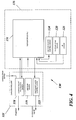
- a control system 130 for operating the waste collection tank 102 of the waste collection system 101 will now be described with specific reference to the schematic drawing figure 4 .
- the method proposed by the invention can be implemented as software, hardware or a combination thereof Preferably, however, the method is implemented as a program, which when running on a PLC (Programmable Logic Controller) 131 or equivalent processor or computer, makes the PLC perform the steps, functions and actions defined in the flow diagram of Figs. 5A-B .
- PLC Programmable Logic Controller
- the relevant steps, functions and actions of the invention are mapped into a program, which is downloaded into the target control system such as a PLC.
- a PLC is a control hub that can be used for a variety of automated applications. They normally contain multiple inputs and outputs that use programmable logic to simulate switches and relays to control equipment.
- the PLC is typically programmable via standard computer interfaces and programming languages.
- the control system 130 is connected to the other components of the waste collection system 101 through conventional communication links that are utilized for receiving signal information from the waste collection system and for sending control signals to the discharge valve 107A, the drive motor 116 and the vacuum source 112.
- the PLC 131 receives information from the described motor load 118, air flow 119, vacuum level 120 and IR 125 sensors of the system 101, and based on this information the program running on the PLC 131 makes the PLC perform a tank operation procedure, for example as described below. The result is that appropriate control signals are sent to a discharge valve control means 123, a conveyor drive motor control means 118 and vacuum source control means 124 for effectuating controlled emptying of the tank 102.
- Fig. 5 is a flow chart summarizing a method for tank operation according to an exemplary embodiment of the present invention.
- a first step S1 after docking the vacuum truck 110 to the docking point 109, the proper tank 102 is chosen by opening the corresponding discharge valve 107A, and the vacuum source 112 is activated to apply full vacuum to the pipe system 108 and the tank discharge section 117.
- the application of vacuum to the tank, through the open discharge valve 107A, is continued for a preset time interval X in step S2. This time interval is chosen to secure that the tapered discharge section 117 is emptied of accumulated waste W at the start of the emptying procedure.
- step 3 after said time interval X, values representative of the air flow through the tank discharge section 117 as well as of the level of vacuum applied to said tank section 117 are then detected by means of the differential pressure sensor 119 and the vacuum level sensor 120, respectively.
- the detected air flow and vacuum level values are compared with selected minimum and maximum threshold values, respectively, in step 4. In the event that any of the detected values lie outside their preset limits, this is an indication that waste W remains in the discharge section 117 and blocks proper air flow there through. If this situation occurs the vacuum application continues for a selected maximum time R in step 5, with repeated detection and comparing of the values.
- the maximum time R is monitored in step 6, and when said time R has expired the procedure is stopped in step 7 by stopping the conveyor and the vacuum application, and the cause of the blocking is investigated. An alarm may be triggered by the expiration of the maximum time R, to make an operator aware of the situation.
- step 8 activation of the agitating and conveying means 113 is allowed in step 8, to cause accumulated waste W from the main section of the tank 102 to be conveyed towards and into the air flow in the discharge section 117.
- waste W is thereby discharged from the tank 102 and into the pipe system 108 by means of the applied vacuum, assisted by the agitating and conveying means 113.
- steps 9 and 10 the air flow and vacuum level values are continuously monitored and compared with the respective selected minimum and maximum threshold values.
- a value representative of the drive torque applied to the agitating and conveying means 113 by the drive motor 116 is also continuously detected and monitored and compared with a selected maximum threshold value during operation of the agitating and conveying means 113.
- the agitating and conveying means 113 is paused by at least temporarily stopping the drive motor 116 for a selected time Y in step 11.
- step 12 Monitoring of the three values and comparing them with the selected threshold values continues in step 12 during pausing of the conveyor means. In case all monitored values return to the correct level, the process reenters the discharge phase with activated conveyor means 113. Otherwise, with any of the values remaining outside the limits after deactivation of the conveying means for a time exceeding the preset time Y, the conveyor means 113 and thus the operation of the agitating and conveying means 113 is reversed in step 13 to attempt to clear any disturbance to the discharge.
- the drive motor 116 and thus the operation of the conveyor means 113 is reversed for a selected and preset time Z and in the situation where any of the monitored values are then still found to be outside the preset limits in step 14, the procedure is stopped in step 15 by stopping the conveyor and the vacuum application, and the cause of the blocking is investigated. In this situation an alarm may likewise be triggered.
- the process proceeds in the discharge phase with activated conveyor means 113.
- the IR-sensor 125 continuously detects waste objects that are being discharged and that block the beam of the sensor. Specifically the sensitivity of the IR sensor 125 is adjusted so that a preset size of the waste object is required in order for the sensor to react upon the blocking of its beam. In other words the passing of minor waste objects will not activate the sensor. If the air flow, vacuum level and motor load values are all within their preset limits and no waste object has passed the sensor 125 for Q seconds the discharge procedure is stopped in step 16.
- the conveyor means 113 and the vacuum application are automatically timed out in step 17 at a maximum discharge phase time T, which completes the discharge procedure. Therefore, this time T is the maximum time period for continuous activation of the agitating and conveying means.
- parameters that are indicative of the waste discharge situation in the tank are detected and used to control the discharge process so that blockage or other disturbance of the discharge process may be prevented by taking appropriate control measures to prevent actual blockage or disturbance from occurring.
- This will provide excellent conditions for performing a rapid and efficient emptying of the waste collection tank, irrespective of its size (within reasonable limits) and will therefore well satisfy the objects of the invention.
- a frequency inverter may be used instead of the described current relay, for controlling the conveyor drive motor 116 and for detecting the motor load.
- the speed of the conveyor means 113 may also be used as a further means for optimizing the waste conveying phase of the discharge.
- the invention also covers the possibility of comparing the detected air flow, vacuum level and motor load values with multiple limits or threshold values and of using the possibility to first change the speed of the conveyor means when a first limit is exceeded and to pause and/or reverse the conveyor only when further limits are exceeded. With such a configuration different basic conveyor speeds may also be chosen for different situations and/or applications.
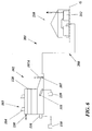
- Fig. 6 is illustrated a tank 102 that is identical to the one used in the system of Fig. 2 , with the exception that a level sensor 230 is illustrated for detecting the fill level of the tank 102.
- level sensors 230 are mainly contemplated for stationary systems, but their use is not excluded from future mobile systems.
- the value of the detected fill level may be employed to set parameters, such as vacuum level, duration of the different described times and, in the applicable case, the speed of the conveyor means.
- one or more such level sensors may be used to detect one or several different fill levels of the tank and the sensors may either be analogous fill level sensors or digital fill level sensors.
- the invention also covers the possibility of using at least one analogous sensor, the output of which is digitalized for control purposes.
- the pipe system 208 connected to the discharge opening 107 of the tank 102 does here lead to a collection station 210 of the general type that is employed for stationary systems, containing a vacuum source 212 and other standard equipment such as a separator, a compactor and filters.
- the invention is not restricted to the use of the presently preferred shaftless type of screw conveyor, but may also employ other available types of conveyors, especially in situations where it is not critical to avoid compression of the waste in the tank.
Landscapes
- Engineering & Computer Science (AREA)
- Mechanical Engineering (AREA)
- Refuse Collection And Transfer (AREA)
Claims (24)
- Verfahren zum Betrieb eines Abfallsammelbehälters (102), der durch mindestens eine Abfallzufuhröffnung (105, 105') periodisch Abfall (W) empfängt und aus dem angesammelter Abfall in Intervallen durch eine Behälterentladungsöffnung (107) entladen wird, wobei der Entladungsprozess durch Anlegen eines Vakuums an den Behälter gestartet wird, und die Abfallentladung durch Erzeugen eines Luftstroms mittels des angelegten Vakuums von einem Einlass für atmosphärische Luft (115) im Behälter und durch die Entladungsöffnung und mit der Unterstützung eines Rühr- und Fördermittels (113) vom Typ eines Schneckenförderers durchgeführt wird, das in der Nähe eines Bodenabschnitts (114) des Behälters getragen wird und das durch einen Antriebsmotor (116) gedreht wird, gekennzeichnet durch Ausführen der folgenden Schritte:- Erfassen zu einer vorbestimmten Zeit (X) nach dem Öffnen eines Entladungsventils (107A), das die Behälterentladungsöffnung (107) steuert, und nach dem Anlegen des Vakuums eines Wertes, der für den Luftstrom durch den Behälter (102) repräsentativ ist, sowie eines Wertes, der für den Pegel des Vakuums repräsentativ ist, das an den Behälter (102) angelegt wird;- Vergleichen der erfassten Werte, die für den Luftstrom und den Vakuumpegel repräsentativ sind, mit ausgewählten Minimal- bzw. Maximalschwellenwerten; und- Aktivieren des Rühr- und Fördermittels (113), wenn die erfassten Luftstrom- und Vakuumpegelwerte über und unter den jeweiligen Schwellenwerten liegen;- um dadurch Abfall mittels des angelegten Vakuums unterstützt vom Rühr- und Fördermittel (113) aus dem Behälter (102) zu entladen.
- Verfahren nach Anspruch 1, gekennzeichnet durch Erfassen eines Differenzdrucks zwischen einem atmosphärischen Luftdruck und einem Druck im Lufteinlass als einen Wert, der für den Luftstrom durch den Behälter (102) repräsentativ ist.
- Verfahren nach Anspruch 1 oder 2, gekennzeichnet durch kontinuierliches Überwachen des erfassten Wertes, der für den Luftstrom im Lufteinlass (115) repräsentativ ist, sowie des Wertes, der für den Vakuumpegel im Behälter (102) repräsentativ ist, während des Betriebs des Rühr- und Fördermittels (113) und Vergleichen derselben mit den jeweiligen Schwellenwerten und durch wenigstens vorübergehendes Deaktivieren des Rühr- und Fördermittels (113), falls einer der Werte unter bzw. über seine Minimal- bzw. Maximalschwellenwerte fällt.
- Verfahren nach Anspruch 3, gekennzeichnet durch kontinuierliches Erfassen eines Wertes, der für die tatsächliche Motorlast repräsentativ ist, die dem Antriebsmotor (116) des Rühr- und Fördermittels auferlegt wird, während des Betriebs des Rühr- und Fördermittels (113) und Vergleichen desselben mit einem ausgewählten Maximalschwellenwert und außerdem durch Deaktivieren des Rühr- und Fördermittels (113), falls der Wert, der für die Motorlast repräsentativ ist, über seinen Maximalschwellenwert fällt.
- Verfahren nach Anspruch 3 oder 4, gekennzeichnet durch Erfassen der Dauer der Deaktivierung des Rühr- und Fördermittels (113) infolgedessen, dass solch ein erfasster Wert über oder unter seinen jeweiligen Schwellenwert fällt, und durch Umkehren des Antriebsmotors (116) und infolgedessen des Betriebs des Rühr- und Fördermittels für eine ausgewählte Zeit (Z), falls die Dauer solch einer Deaktivierung des Rühr- und Fördermittels eine ausgewählte Zeit (Y) überschreitet.
- Verfahren nach Anspruch 5, gekennzeichnet durch Durchführen der Umkehrung des Antriebsmotors (116) und infolgedessen des Betriebs des Rühr- und Fördermittels (113) für eine ausgewählte Zeit (Z) von ungefähr 2 bis 5 Sekunden.
- Verfahren nach Anspruch 5 oder 6, gekennzeichnet durch Umkehren des Antriebsmotors (116) und infolgedessen des Betriebs des Rühr- und Fördermittels (113) nach einer Deaktivierung des Rühr- und Fördermittels, die eine ausgewählte Zeit (Y) von ungefähr 4 bis 5 Sekunden überschreitet.
- Verfahren nach einem der Ansprüche 1 bis 7, gekennzeichnet durch Aktivieren des Rühr- und Fördermittels (113) für eine maximale kontinuierliche Zeitspanne (T) von ungefähr 3 Minuten.
- Verfahren nach einem der Ansprüche 1 bis 8, gekennzeichnet durch kontinuierliches Erfassen des Stroms von Abfallmaterial (W) aus dem Behälter (102) und durch Deaktivieren des Rühr- und Fördermittels (113), Unterbrechen des Anlegens von Vakuum an den Behälter und gegebenenfalls Schließen der Behälterentladungsöffnung (107), wenn für eine voreingestellte Zeitspanne (R) kein Strom von Abfallmaterial erfasst wurde.
- Verfahren nach einem der Ansprüche 1 bis 9, gekennzeichnet durch Regeln der Drehgeschwindigkeit des Rühr- und Fördermittels (113) in Abhängigkeit von den erfassten Luftstrom-, Vakuumpegel- und/oder Antriebsmomentwerten.
- Verfahren nach einem der Ansprüche 1 bis 10, gekennzeichnet durch Anlegen des Vakuums von einer Vakuumquelle (112), die sich in einem mobilen Sammelfahrzeug (110) befindet.
- Verfahren nach einem der Ansprüche 1 bis 10, gekennzeichnet durch Anlegen des Vakuums von einer Vakuumquelle (212) eines stationären Abfallsammelsystems (201).
- Verfahren nach einem der Ansprüche 1 bis 12, gekennzeichnet durch Erfassen des Luftstromwerts sowie des Vakuumpegelwerts ungefähr 15 Sekunden nach Beginn des Entladungsprozesses.
- System zum Steuern des Betriebs eines Abfallsammelbehälters (102) mit mindestens einer Abfallzufuhröffnung (105), durch welche Abfall (W) empfangen wird, einer Behälterentladungsöffnung (107), durch welche angesammelter Abfall in ein Entladungsrohrsystem (108; 208) entladen wird, einem Einlass für atmosphärische Luft (115) im Behälter, einem Rühr- und Fördermittel (113), das durch einen Antriebsmotor (116) gedreht und in der Nähe eines Bodenabschnitts (114) des Behälters getragen wird, und einer Vakuumquelle (112, 212), die mit dem Rohrsystem (108; 208) zum Anlegen eines Vakuums an den Behälter (102) durch die Entladungsöffnung (107) in Verbindung steht, gekennzeichnet durch:- Mittel (119) zum Erfassen eines Wertes, der für den Luftstrom durch den Behälter (102) repräsentativ ist;- Mittel (120) zum Erfassen eines Wertes, der für den Vakuumpegel im Rohrsystem (108; 208) repräsentativ ist; und- Mittel (130) zum Empfangen von Informationen von den Erfassungsmitteln (119, 120) zum Vergleichen der empfangenen Informationen mit voreingestellten Schwellenwerten und zum Steuern des Betriebs des Rühr- und Fördermittels (113) und Anlegen des Vakuums basierend auf dem Vergleich.
- System nach Anspruch 14, gekennzeichnet durch Mittel (118) zum Erfassen eines Wertes, der für die Motorlast repräsentativ ist, die dem Antriebsmotor (116) während des Betriebs des Rühr- und Fördermittels (113) auferlegt wird.
- System nach Anspruch 15, dadurch gekennzeichnet, dass das Mittel (118) zum Erfassen eines Wertes, der für die Motorlast repräsentativ ist, die dem Antriebsmotor (116) auferlegt wird, ein Stromrelais ist, das den Motor steuert.
- System nach Anspruch 15, dadurch gekennzeichnet, dass das Mittel (118) zum Erfassen eines Wertes, der für die Motorlast repräsentativ ist, die dem Antriebsmotor (116) auferlegt wird, ein Frequenzumrichter zum Steuern des Antriebsmotors (116) ist.
- System nach einem der Ansprüche 14 bis 17, dadurch gekennzeichnet, dass das Mittel (119) zum Erfassen eines Wertes, der für den Luftstrom durch den Behälter (102) repräsentativ ist, ein Drucksensor ist, der einen Differenzdruck zwischen einem atmosphärischen Druck und einem Luftdruck im Lufteinlass (115) erfasst.
- System nach einem der Ansprüche 14 bis 18, gekennzeichnet durch Mittel (125) zum Erfassen des Durchtritts von Abfallmaterial (W) durch das Rohrsystem (108, 111).
- System nach einem der Ansprüche 14 bis 19, dadurch gekennzeichnet, dass das Mittel (130) zum Empfangen von Informationen von den Erfassungsmitteln und zum Steuern des Betriebs des Rühr- und Fördermittels (113) und zum Anlegen des Vakuums eine programmierbare logische Steuerung (131) umfasst.
- System nach einem der Ansprüche 14 bis 20, dadurch gekennzeichnet, dass die Vakuumquelle (112) in ein mobiles Sammelfahrzeug (110) integriert ist.
- System nach einem der Ansprüche 14 bis 20, dadurch gekennzeichnet, dass die Vakuumquelle (212) Teil eines stationären Abfallsammelsystems (201) ist.
- System nach einem der Ansprüche 14 bis 22, gekennzeichnet durch einen oder mehrere analoge oder digitale Füllstandsensoren (230) im Behälter (102) zum Erfassen von Abfallfüllständen darin.
- System nach einem der Ansprüche 14 bis 23, dadurch gekennzeichnet, dass das Rühr- und Fördermittel (113) ein achsloser Schneckenförderer ist, der von einer Behälterwand (102A) vorsteht.
Applications Claiming Priority (1)
| Application Number | Priority Date | Filing Date | Title |
|---|---|---|---|
| PCT/SE2005/000971 WO2006135296A1 (en) | 2005-06-17 | 2005-06-17 | A method of operating a waste collection tank and a system for controlling the operation of the same |
Publications (2)
| Publication Number | Publication Date |
|---|---|
| EP1893509A1 EP1893509A1 (de) | 2008-03-05 |
| EP1893509B1 true EP1893509B1 (de) | 2016-06-08 |
Family
ID=37532565
Family Applications (1)
| Application Number | Title | Priority Date | Filing Date |
|---|---|---|---|
| EP05753921.5A Expired - Lifetime EP1893509B1 (de) | 2005-06-17 | 2005-06-17 | Verfahren zum betrieb eines abfallsammelbehälters und system zur steuerung von dessen betrieb |
Country Status (4)
| Country | Link |
|---|---|
| EP (1) | EP1893509B1 (de) |
| DK (1) | DK1893509T3 (de) |
| ES (1) | ES2589780T3 (de) |
| WO (1) | WO2006135296A1 (de) |
Families Citing this family (13)
| Publication number | Priority date | Publication date | Assignee | Title |
|---|---|---|---|---|
| WO2008130289A1 (en) * | 2007-04-20 | 2008-10-30 | Envac Ab | Waste collection |
| SE532831C2 (sv) * | 2007-06-11 | 2010-04-20 | Envac Ab | Ett vakuumdrivet avfallsinsamlingssystem och en metod för att tömma en central avfallslagringstank |
| DK2059462T3 (da) * | 2007-06-11 | 2012-10-22 | Envac Ab | Anlæg til indsamling og midlertidig opbevaring af affald |
| DK2200910T3 (da) * | 2007-09-18 | 2020-03-30 | Envac Ab | Affaldsopbevaring |
| US20110293392A1 (en) * | 2009-02-03 | 2011-12-01 | Envac Ab | Vacuum operated waste collection container and a use of the container |
| DE202009001500U1 (de) | 2009-02-07 | 2009-04-09 | SL Rasch GmbH Special & Lightweight Structures | Speichervorrichtung für ein pneumatisches Müllsaugsystem |
| DE102009007820A1 (de) | 2009-02-07 | 2010-08-26 | SL Rasch GmbH Special & Lightweight Structures | Speichervorrichtung für ein pneumatisches Müllsystem, pneumatisches Müllsaugsystem sowie ein Verfahren zum Überführen von Müllobjekten mittels eines solchen Müllsaugsystems |
| ES2998033T3 (en) | 2010-03-04 | 2025-02-18 | Envac Ab | Waste emptying control |
| FI20126192A7 (fi) * | 2011-12-02 | 2013-06-03 | Maricap Oy | Menetelmä ja laitteisto materiaalin syöttämiseksi pneumaattisessa jätteiden putkikuljetusjärjestelmässä |
| FI124175B (fi) | 2012-08-22 | 2014-04-15 | Maricap Oy | Menetelmä materiaalin käsittelemiseksi materiaalinsiirtojärjestelmässä, materiaalinsiirtojärjestelmä ja materiaalinsiirtojärjestelmän erotinlaite |
| WO2016054235A1 (en) * | 2014-10-01 | 2016-04-07 | Emerson Electric Co. | Monitoring and control of blanketing gas for food waste disposal, storage, and treatment system |
| JP6435566B1 (ja) * | 2018-01-26 | 2018-12-12 | 三菱重工環境・化学エンジニアリング株式会社 | ごみ真空輸送システム及びごみ真空輸送システムの改造方法 |
| CN112265754B (zh) * | 2020-10-15 | 2022-12-23 | 国网浙江省电力有限公司台州供电公司 | 一种建筑楼宇用垃圾清理方法及系统 |
Family Cites Families (7)
| Publication number | Priority date | Publication date | Assignee | Title |
|---|---|---|---|---|
| JP2645843B2 (ja) * | 1988-02-02 | 1997-08-25 | 新明和工業株式会社 | 塵芥貯留容器 |
| JPH064444B2 (ja) * | 1989-03-27 | 1994-01-19 | 新明和工業株式会社 | ゴミ吸引輸送装置 |
| JPH069006A (ja) * | 1992-03-16 | 1994-01-18 | Shin Meiwa Ind Co Ltd | ゴミ貯留輸送装置 |
| JP3091636B2 (ja) * | 1994-05-19 | 2000-09-25 | 日本鋼管工事株式会社 | ごみ排出制御方法 |
| JPH08165004A (ja) * | 1994-12-09 | 1996-06-25 | Japan Steel & Tube Constr Co Ltd | 長距離ごみ排出制御方法 |
| JP2839140B2 (ja) * | 1997-04-30 | 1998-12-16 | 新明和工業株式会社 | 塵芥収集システム |
| SE9900401L (sv) * | 1999-02-05 | 2000-04-10 | Centralsug Int Ab | Sätt och anordning vid tömning av en expanderad lagringsvolym i ett avfallstransportsystem |
-
2005
- 2005-06-17 ES ES05753921.5T patent/ES2589780T3/es not_active Expired - Lifetime
- 2005-06-17 WO PCT/SE2005/000971 patent/WO2006135296A1/en not_active Ceased
- 2005-06-17 EP EP05753921.5A patent/EP1893509B1/de not_active Expired - Lifetime
- 2005-06-17 DK DK05753921.5T patent/DK1893509T3/en active
Also Published As
| Publication number | Publication date |
|---|---|
| ES2589780T3 (es) | 2016-11-16 |
| WO2006135296A1 (en) | 2006-12-21 |
| DK1893509T3 (en) | 2016-09-19 |
| EP1893509A1 (de) | 2008-03-05 |
Similar Documents
| Publication | Publication Date | Title |
|---|---|---|
| DK1893509T3 (en) | PROCEDURE FOR OPERATING A WASTE CONTAINER AND SYSTEM FOR REGULATING THE OPERATION THEREOF | |
| US8544775B2 (en) | Putrescible organic waste treatment | |
| CN104971932B (zh) | 一种餐厨余垃圾回收再利用环保节能系统 | |
| KR101765139B1 (ko) | 볼밸브를 이용한 주방용 음식물쓰레기 종량 투입장치 및 이를 구비한 음식물쓰레기 처리시스템 | |
| CN102892691B (zh) | 废料排空控制 | |
| KR101089807B1 (ko) | 세대별 음식물 쓰레기 처리장치 | |
| US9211544B2 (en) | Organic shredder apparatus and method for operating an organic shredder | |
| US8844848B2 (en) | Waste disposal apparatus, fluid and method | |
| CN211660713U (zh) | 一种餐厨垃圾处理机 | |
| US20010006198A1 (en) | Device and method for shredding food waste | |
| EP1472163B1 (de) | Verfahren zur verarbeitung von küchenabfall | |
| SE529358C2 (sv) | Körmetod för lagringstank | |
| KR200284794Y1 (ko) | 쓰레기 수거차량의 오수처리장치 | |
| JP3407774B2 (ja) | 生ごみ処理機 | |
| CN221031192U (zh) | 一种适用于高层建筑的垃圾回收装置 | |
| EP2747909B1 (de) | Abfallentsorgungsvorrichtung | |
| KR100414329B1 (ko) | 음식물쓰레기 자동처리시스템 및 그것의 운영방법 | |
| KR200259152Y1 (ko) | 음식물쓰레기 자동처리시스템 | |
| CN116513757B (en) | Control method and device for return cleaning of conveyor belt | |
| KR100266395B1 (ko) | 음식물 쓰레기 수거장치 | |
| JP2006256789A (ja) | 家屋内廃棄処理物の排出装置 | |
| JP2509952Y2 (ja) | ゴミ貯留収集装置 | |
| KR20000020117U (ko) | 공기압 쓰레기 집하 시스템 | |
| CN115787795A (zh) | 一种厨余垃圾处理器及工作方法 | |
| CN108861645A (zh) | 一种用于水果加工的出料接料装置及控制方法 |
Legal Events
| Date | Code | Title | Description |
|---|---|---|---|
| PUAI | Public reference made under article 153(3) epc to a published international application that has entered the european phase |
Free format text: ORIGINAL CODE: 0009012 |
|
| 17P | Request for examination filed |
Effective date: 20080117 |
|
| AK | Designated contracting states |
Kind code of ref document: A1 Designated state(s): AT BE BG CH CY CZ DE DK EE ES FI FR GB GR HU IE IS IT LI LT LU MC NL PL PT RO SE SI SK TR |
|
| DAX | Request for extension of the european patent (deleted) | ||
| RAP1 | Party data changed (applicant data changed or rights of an application transferred) |
Owner name: ENVAC AB |
|
| GRAP | Despatch of communication of intention to grant a patent |
Free format text: ORIGINAL CODE: EPIDOSNIGR1 |
|
| INTG | Intention to grant announced |
Effective date: 20160112 |
|
| GRAS | Grant fee paid |
Free format text: ORIGINAL CODE: EPIDOSNIGR3 |
|
| GRAA | (expected) grant |
Free format text: ORIGINAL CODE: 0009210 |
|
| AK | Designated contracting states |
Kind code of ref document: B1 Designated state(s): AT BE BG CH CY CZ DE DK EE ES FI FR GB GR HU IE IS IT LI LT LU MC NL PL PT RO SE SI SK TR |
|
| RAP1 | Party data changed (applicant data changed or rights of an application transferred) |
Owner name: ENVAC AB |
|
| REG | Reference to a national code |
Ref country code: GB Ref legal event code: FG4D |
|
| REG | Reference to a national code |
Ref country code: CH Ref legal event code: EP |
|
| REG | Reference to a national code |
Ref country code: IE Ref legal event code: FG4D |
|
| REG | Reference to a national code |
Ref country code: AT Ref legal event code: REF Ref document number: 805058 Country of ref document: AT Kind code of ref document: T Effective date: 20160715 |
|
| REG | Reference to a national code |
Ref country code: DE Ref legal event code: R096 Ref document number: 602005049497 Country of ref document: DE |
|
| REG | Reference to a national code |
Ref country code: FR Ref legal event code: PLFP Year of fee payment: 12 |
|
| REG | Reference to a national code |
Ref country code: DK Ref legal event code: T3 Effective date: 20160913 |
|
| REG | Reference to a national code |
Ref country code: LT Ref legal event code: MG4D |
|
| REG | Reference to a national code |
Ref country code: NL Ref legal event code: MP Effective date: 20160608 |
|
| PG25 | Lapsed in a contracting state [announced via postgrant information from national office to epo] |
Ref country code: LT Free format text: LAPSE BECAUSE OF FAILURE TO SUBMIT A TRANSLATION OF THE DESCRIPTION OR TO PAY THE FEE WITHIN THE PRESCRIBED TIME-LIMIT Effective date: 20160608 |
|
| REG | Reference to a national code |
Ref country code: AT Ref legal event code: MK05 Ref document number: 805058 Country of ref document: AT Kind code of ref document: T Effective date: 20160608 |
|
| REG | Reference to a national code |
Ref country code: ES Ref legal event code: FG2A Ref document number: 2589780 Country of ref document: ES Kind code of ref document: T3 Effective date: 20161116 |
|
| PG25 | Lapsed in a contracting state [announced via postgrant information from national office to epo] |
Ref country code: SE Free format text: LAPSE BECAUSE OF FAILURE TO SUBMIT A TRANSLATION OF THE DESCRIPTION OR TO PAY THE FEE WITHIN THE PRESCRIBED TIME-LIMIT Effective date: 20160608 Ref country code: GR Free format text: LAPSE BECAUSE OF FAILURE TO SUBMIT A TRANSLATION OF THE DESCRIPTION OR TO PAY THE FEE WITHIN THE PRESCRIBED TIME-LIMIT Effective date: 20160909 Ref country code: NL Free format text: LAPSE BECAUSE OF FAILURE TO SUBMIT A TRANSLATION OF THE DESCRIPTION OR TO PAY THE FEE WITHIN THE PRESCRIBED TIME-LIMIT Effective date: 20160608 |
|
| PG25 | Lapsed in a contracting state [announced via postgrant information from national office to epo] |
Ref country code: BE Free format text: LAPSE BECAUSE OF NON-PAYMENT OF DUE FEES Effective date: 20160630 |
|
| REG | Reference to a national code |
Ref country code: DE Ref legal event code: R119 Ref document number: 602005049497 Country of ref document: DE |
|
| PG25 | Lapsed in a contracting state [announced via postgrant information from national office to epo] |
Ref country code: SK Free format text: LAPSE BECAUSE OF FAILURE TO SUBMIT A TRANSLATION OF THE DESCRIPTION OR TO PAY THE FEE WITHIN THE PRESCRIBED TIME-LIMIT Effective date: 20160608 Ref country code: IS Free format text: LAPSE BECAUSE OF FAILURE TO SUBMIT A TRANSLATION OF THE DESCRIPTION OR TO PAY THE FEE WITHIN THE PRESCRIBED TIME-LIMIT Effective date: 20161008 Ref country code: CZ Free format text: LAPSE BECAUSE OF FAILURE TO SUBMIT A TRANSLATION OF THE DESCRIPTION OR TO PAY THE FEE WITHIN THE PRESCRIBED TIME-LIMIT Effective date: 20160608 Ref country code: EE Free format text: LAPSE BECAUSE OF FAILURE TO SUBMIT A TRANSLATION OF THE DESCRIPTION OR TO PAY THE FEE WITHIN THE PRESCRIBED TIME-LIMIT Effective date: 20160608 Ref country code: RO Free format text: LAPSE BECAUSE OF FAILURE TO SUBMIT A TRANSLATION OF THE DESCRIPTION OR TO PAY THE FEE WITHIN THE PRESCRIBED TIME-LIMIT Effective date: 20160608 |
|
| REG | Reference to a national code |
Ref country code: CH Ref legal event code: PL |
|
| PG25 | Lapsed in a contracting state [announced via postgrant information from national office to epo] |
Ref country code: BE Free format text: LAPSE BECAUSE OF FAILURE TO SUBMIT A TRANSLATION OF THE DESCRIPTION OR TO PAY THE FEE WITHIN THE PRESCRIBED TIME-LIMIT Effective date: 20160608 Ref country code: PL Free format text: LAPSE BECAUSE OF FAILURE TO SUBMIT A TRANSLATION OF THE DESCRIPTION OR TO PAY THE FEE WITHIN THE PRESCRIBED TIME-LIMIT Effective date: 20160608 Ref country code: PT Free format text: LAPSE BECAUSE OF FAILURE TO SUBMIT A TRANSLATION OF THE DESCRIPTION OR TO PAY THE FEE WITHIN THE PRESCRIBED TIME-LIMIT Effective date: 20161010 Ref country code: AT Free format text: LAPSE BECAUSE OF FAILURE TO SUBMIT A TRANSLATION OF THE DESCRIPTION OR TO PAY THE FEE WITHIN THE PRESCRIBED TIME-LIMIT Effective date: 20160608 |
|
| REG | Reference to a national code |
Ref country code: IE Ref legal event code: MM4A |
|
| PG25 | Lapsed in a contracting state [announced via postgrant information from national office to epo] |
Ref country code: MC Free format text: LAPSE BECAUSE OF FAILURE TO SUBMIT A TRANSLATION OF THE DESCRIPTION OR TO PAY THE FEE WITHIN THE PRESCRIBED TIME-LIMIT Effective date: 20160608 |
|
| PLBE | No opposition filed within time limit |
Free format text: ORIGINAL CODE: 0009261 |
|
| STAA | Information on the status of an ep patent application or granted ep patent |
Free format text: STATUS: NO OPPOSITION FILED WITHIN TIME LIMIT |
|
| PG25 | Lapsed in a contracting state [announced via postgrant information from national office to epo] |
Ref country code: CH Free format text: LAPSE BECAUSE OF NON-PAYMENT OF DUE FEES Effective date: 20160630 Ref country code: LI Free format text: LAPSE BECAUSE OF NON-PAYMENT OF DUE FEES Effective date: 20160630 Ref country code: DE Free format text: LAPSE BECAUSE OF NON-PAYMENT OF DUE FEES Effective date: 20170103 |
|
| 26N | No opposition filed |
Effective date: 20170309 |
|
| PG25 | Lapsed in a contracting state [announced via postgrant information from national office to epo] |
Ref country code: IE Free format text: LAPSE BECAUSE OF NON-PAYMENT OF DUE FEES Effective date: 20160617 Ref country code: SI Free format text: LAPSE BECAUSE OF FAILURE TO SUBMIT A TRANSLATION OF THE DESCRIPTION OR TO PAY THE FEE WITHIN THE PRESCRIBED TIME-LIMIT Effective date: 20160608 |
|
| REG | Reference to a national code |
Ref country code: FR Ref legal event code: PLFP Year of fee payment: 13 |
|
| PG25 | Lapsed in a contracting state [announced via postgrant information from national office to epo] |
Ref country code: HU Free format text: LAPSE BECAUSE OF FAILURE TO SUBMIT A TRANSLATION OF THE DESCRIPTION OR TO PAY THE FEE WITHIN THE PRESCRIBED TIME-LIMIT; INVALID AB INITIO Effective date: 20050617 Ref country code: CY Free format text: LAPSE BECAUSE OF FAILURE TO SUBMIT A TRANSLATION OF THE DESCRIPTION OR TO PAY THE FEE WITHIN THE PRESCRIBED TIME-LIMIT Effective date: 20160608 |
|
| REG | Reference to a national code |
Ref country code: FR Ref legal event code: PLFP Year of fee payment: 14 |
|
| PG25 | Lapsed in a contracting state [announced via postgrant information from national office to epo] |
Ref country code: TR Free format text: LAPSE BECAUSE OF FAILURE TO SUBMIT A TRANSLATION OF THE DESCRIPTION OR TO PAY THE FEE WITHIN THE PRESCRIBED TIME-LIMIT Effective date: 20160608 Ref country code: LU Free format text: LAPSE BECAUSE OF NON-PAYMENT OF DUE FEES Effective date: 20160617 |
|
| PG25 | Lapsed in a contracting state [announced via postgrant information from national office to epo] |
Ref country code: BG Free format text: LAPSE BECAUSE OF FAILURE TO SUBMIT A TRANSLATION OF THE DESCRIPTION OR TO PAY THE FEE WITHIN THE PRESCRIBED TIME-LIMIT Effective date: 20160608 |
|
| PGFP | Annual fee paid to national office [announced via postgrant information from national office to epo] |
Ref country code: IT Payment date: 20200428 Year of fee payment: 16 |
|
| PG25 | Lapsed in a contracting state [announced via postgrant information from national office to epo] |
Ref country code: IT Free format text: LAPSE BECAUSE OF NON-PAYMENT OF DUE FEES Effective date: 20210617 |
|
| PGFP | Annual fee paid to national office [announced via postgrant information from national office to epo] |
Ref country code: GB Payment date: 20220517 Year of fee payment: 18 Ref country code: FR Payment date: 20220518 Year of fee payment: 18 |
|
| PGFP | Annual fee paid to national office [announced via postgrant information from national office to epo] |
Ref country code: FI Payment date: 20220518 Year of fee payment: 18 |
|
| PG25 | Lapsed in a contracting state [announced via postgrant information from national office to epo] |
Ref country code: FI Free format text: LAPSE BECAUSE OF NON-PAYMENT OF DUE FEES Effective date: 20230617 |
|
| GBPC | Gb: european patent ceased through non-payment of renewal fee |
Effective date: 20230617 |
|
| PG25 | Lapsed in a contracting state [announced via postgrant information from national office to epo] |
Ref country code: GB Free format text: LAPSE BECAUSE OF NON-PAYMENT OF DUE FEES Effective date: 20230617 |
|
| PG25 | Lapsed in a contracting state [announced via postgrant information from national office to epo] |
Ref country code: FR Free format text: LAPSE BECAUSE OF NON-PAYMENT OF DUE FEES Effective date: 20230630 |
|
| PGFP | Annual fee paid to national office [announced via postgrant information from national office to epo] |
Ref country code: DK Payment date: 20240516 Year of fee payment: 20 |
|
| PGFP | Annual fee paid to national office [announced via postgrant information from national office to epo] |
Ref country code: ES Payment date: 20240701 Year of fee payment: 20 |
|
| REG | Reference to a national code |
Ref country code: DK Ref legal event code: EUP Expiry date: 20250617 |
|
| REG | Reference to a national code |
Ref country code: ES Ref legal event code: FD2A Effective date: 20250626 |
|
| PG25 | Lapsed in a contracting state [announced via postgrant information from national office to epo] |
Ref country code: ES Free format text: LAPSE BECAUSE OF EXPIRATION OF PROTECTION Effective date: 20250618 |