EP1893512B1 - Automatischer entpalettierer - Google Patents
Automatischer entpalettierer Download PDFInfo
- Publication number
- EP1893512B1 EP1893512B1 EP06701598A EP06701598A EP1893512B1 EP 1893512 B1 EP1893512 B1 EP 1893512B1 EP 06701598 A EP06701598 A EP 06701598A EP 06701598 A EP06701598 A EP 06701598A EP 1893512 B1 EP1893512 B1 EP 1893512B1
- Authority
- EP
- European Patent Office
- Prior art keywords
- head
- block
- blocks
- sensor
- pickup head
- Prior art date
- Legal status (The legal status is an assumption and is not a legal conclusion. Google has not performed a legal analysis and makes no representation as to the accuracy of the status listed.)
- Expired - Lifetime
Links
Images




Classifications
-
- B—PERFORMING OPERATIONS; TRANSPORTING
- B65—CONVEYING; PACKING; STORING; HANDLING THIN OR FILAMENTARY MATERIAL
- B65G—TRANSPORT OR STORAGE DEVICES, e.g. CONVEYORS FOR LOADING OR TIPPING, SHOP CONVEYOR SYSTEMS OR PNEUMATIC TUBE CONVEYORS
- B65G61/00—Use of pick-up or transfer devices or of manipulators for stacking or de-stacking articles not otherwise provided for
-
- B—PERFORMING OPERATIONS; TRANSPORTING
- B65—CONVEYING; PACKING; STORING; HANDLING THIN OR FILAMENTARY MATERIAL
- B65G—TRANSPORT OR STORAGE DEVICES, e.g. CONVEYORS FOR LOADING OR TIPPING, SHOP CONVEYOR SYSTEMS OR PNEUMATIC TUBE CONVEYORS
- B65G59/00—De-stacking of articles
- B65G59/02—De-stacking from the top of the stack
Definitions
- the present invention relates to an automatic depalletizer for unloading palletized blocks of material. More in detail, the invention relates to a depalletizer that is particularly suitable for unloading palletized blocks of raw rubber for industrial use.
- Depalletization is a very common task in the field of material handling, essentially consisting in unloading single objects from a pallet to send them to a subsequent processing step.
- Such machines substantially work with an arm adapted to pick up the palletized objects, and transfer them to the outlet of the machine, typically on a conveyor belt; the arm is controlled by a more or less complex program (software).
- US 6022187 discloses a depalletizing machine that takes individual stacks of blanks for cigarette packets from a pallet and feeds them for further processing to a conveyor.
- Said machine includes full three dimensional movability of a pickup arm, a pivotal pickup head, an optical sensor and an electronic control system.
- the invention is particularly directed to the application of unloading pallets of blocks of rubber.
- Rubber for industrial processes of melting, moulding, etc... is available in the form of blocks or "batches" of about 20-30 kg each. These blocks are generally palletized in a quite irregular manner, for some reasons including: the shape of the blocks is approximately parallelepipedon but still irregular, as the material is intended for cutting or melting; the blocks are still hot when they are stacked, so that they buckle bending the stacks in one direction or the other; the pallets have non-standard sizes, as they come from different regions of the world.
- Another problem is that different grades of rubber are normally used, so that dimensions, hardness and weight of the blocks may change from one material to another. Obviously, an automatic depalletizing machine should be able to cope with this variability of the material.
- the object of the invention is to provide a solution to the problem, overcoming the disadvantages of the prior art.
- the object is to provide an automatic depalletizer suitable for moving blocks of material, particularly rubber, adapted to work in a completely automatic mode on irregular pallets, also comprising blocks with non-uniform shape and/or dimensions.
- a further object is a depalletizer adapted to cope with blocks of different material, in particular of different consistency and hardness.
- an object of the invention is a depalletizer adapted to manage blocks made of soft or hard rubber, particularly in the range 30 - 80 Shore.
- Another purpose of the invention is a reasonable complexity and cost of the machine, taking into account the field of application.
- the machine is particularly adapted to work with palletized blocks of rubber, for the above explained reasons.
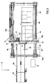
- a depalletizing machine (or depalletizer) is shown, with a motion unit 1, a pickup head 2 and a belt conveyor 3 as basic parts.
- the machine comprises a loading station 4, that corresponds to an area intended to receive palletized blocks of raw material, and an unloading station 5, where each single block can be released onto the conveyor 3.
- Fig. 1 shows two pallets of material in the loading station 4, in particular formed by blocks (or balls) of rubber; the pallets are shown as P1 and P2.
- the machine also comprises a control panel 6 housing an electronic board, storing a program for operation in automatic mode.
- the motion system 1 consist of a cartesian robot with 3+1 degrees of freedom for the pickup head 2. It gives the head 2 a free linear movement on the three axes X, Y and Z respectively longitudinal, transverse and vertical (as shown); it is furthermore able to rotate the head 2 around the vertical axis Z.
- Said motion system in greater detail, has an overhead-crane structure with longitudinal beams 10 and uprights 11.
- the beams 10 carry X-oriented linear guides 12.
- the overhead-crane structure comprises a movable crosspiece, consisting of an Y-oriented linear guide 14 mounted on sliding shoes 13 ( Fig. 2 ); a motor-driven carriage 15 is running on said linear guide 14 and supports a third, vertically-oriented linear guide 16, which is sliding in the vertical direction with respect to said carriage 15.
- the motors are epicyclic coaxial reduction gears, coupled with three-phase asynchronous motors; the X, Y and Z motors are shown in Fig. 2 respectively as 18x, 18y and 18z.
- the motor 18x is mounted on the overhead-crane structure; the motor 18y is mounted on the guide 14 and the motor 18z on the carriage 15.
- the head 2 is mounted on the lower end of the vertical guide 16, coupled to a pneumatic actuator 17 enabling 90-degree rotation of said head 2 around the Z axis.
- the head 2 comprises an optical sensor 20, mounted in a central and frontal position, and three helicoidal-tip tools 21, mounted on a lower face of the head 2.
- the optical sensor 20 has a digital output and an analogue output; said sensor then provides a digital signal, stating the presence of material in front of the head and enabling to scan the pallets, and an analogue signal proportional to the distance on the Y axis between a block and the head.
- the analogue signal is used for positioning the head right above the blocks, as will be explained below.
- the sensor 20 is preferably an infrared laser sensor.
- the tools 21 are arranged, in a preferred embodiment, at the tops of a triangle, as illustrated in Fig. 4 .
- Each tool 21 is operated by a reversible pneumatic motor 22.
- the unit formed by tools 21 and motors 22 is mounted on a moving plate 23; said moving plate 23 can be extended and retracted in the vertical direction, by dual-effect pneumatic actuators 24.
- the head 2 also comprises two pneumatic cylinders 25, each fitted with a rod 26 extending downwards below the plate 23, and acting as a probe and position transducer.
- Each cylinder 25 is equipped with two magnetic proximity sensors 27a and 27b, mounted at different heights to provide a sequence of two outputs when rod 26 is moving. Said two signals can be used for slowing down and stopping the head 2.
- Two probe cylinders 25 are provided, one for each side, arranged as in Fig. 4 .
- the frame structure of the head is substantially a box structure formed by bolted aluminium alloy plates. More in detail, the structure of the head consists essentially of a plate 60 fixed to the shaft of the pneumatic motor 17, and two side plates 61 supporting a central bracket 62. A protective guard (not shown) can be mounted.
- the actuators 24 are fixed to the side plates 61; the pneumatic cylinders 25 and the sensor 20 are fixed to the bracket 62.
- the pneumatic motors 22 are fixed to the moving plate 23 by suitable clamping collars 63; the drills 21 are locked on the shafts of the motors 22 by means of a sleeve 64, having one end fixed to the motor shaft by a key, and the other end supporting the tip 21 inserted and locked by a bolt acting as a plug.
- the plate 23 has an octagonal shape, with two passing slots 65 ( Fig. 4 ) corresponding to the probe cylinders 25.
- the motors and pneumatic cylinders are controlled by a pneumatic circuit with solenoid valves that open and close the compressed-air supply using prior-art techniques.
- the components of the pneumatic circuit are not shown.
- the belt conveyor 3 has a first belt 30, about three metres long, and a second belt 31 about 1 metre long and acting as a magazine.
- the conveyors are provided with a smooth PVC belt and the respective drive rollers are rotated by screw-feed motor-driven reduction gears.
- a photoelectric cell sensor 32 is positioned at the starting point of the belt 30, with upwards orientation.
- the loading station 4 comprises two substations, made in particular by two steel bases 40 and 41. These bases constitute a reference for positioning the pallets loaded with blocks of material, to allow a precise execution of the machine's working program.
- the unloading station 5 corresponds to the portion of space above the end of the belt 30, where the sensor 32 is also located.
- the machine is also provided with suitable safety guards, both passive to prevent access to the zones in which the moving members operate, and active, to stop the machine in case of an emergency.
- These guards may, for example, include welded mesh panels around the moving zone of the pickup head 2; an access gate with microswitch that stops the machine if the gate is opened whilst the machine is running; a photoelectric safety barrier at the front pallet-loading side.
- the control panel 6 controls the position of the axes, operation of grasping means and movement of the conveyors.
- the user interface consists of a switch panel through which commands can be given to the machine, and a display showing operating parameters, and can also be used for manual operation mode.
- control panel 6 houses the electronic control system that provides automatic operation of the machine.
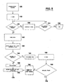
- the automatic wotking program substantially carries out the steps of scanning the pallet by means of the sensor 20 mounted on the head 2 and progressively unloading the pallets from top to bottom, by horizontal rows.
- the control of motors 22 provides a double stop condition, that is i) limit switch reached by movable plane 23 or ii) operating timeout (e.g. 2.5 s) reached.
- This double stop condition enables a secure pickup of both soft and hard materials: in case of a soft block, the drills 21 can easily penetrate through the block itself and motors are stopped by the plate 23 reaching the limit switch; with a hard material, the action of drills 21 is more difficult and the stop occurs because of timeout. Further insistence with action of the drills 21, in fact, would be a loss of time and may even be harmful.
- the machine has selected the next block to unload, which may be the block detected with the first vertical scan, or the first block detected with the next horizontal scan.
Landscapes
- Specific Conveyance Elements (AREA)
- Load-Engaging Elements For Cranes (AREA)
- Fats And Perfumes (AREA)
- Vending Machines For Individual Products (AREA)
Claims (10)
- Depalettiermaschine für Rohmaterialblöcke auf Paletten, insbesondere Gummi, wobei genannte Maschine aus einer für den Empfang der Paletten (P1, P2) geeigneten Ladestation (4) und einer für den Empfang von einzelnen depalettierten Blöcken geeigneten Abladestation (5) besteht, in der- die Maschine einen an ein Bewegungssystem (1) angekoppelten Bearbeitungskopf (2) umfasst, der auf drei kartesischen Achsen längs (X), quer (Y) und vertikal (Z) wirkt, mit Drehung zwischen der vertikalen Achse (Z) zum Bewegen des genannten Bearbeitungskopfes (2) zwischen der Ladestation (4) und der Abladestation (5);- der Bearbeitungskopf (2) mit mindestens einem optischen Sensor (20) ausgestattet ist, geeignet zum Ermitteln des Vorhandenseins eines Materialblocks gegenüber genannten Kopfes (2) und zum Messen der Entfernung zwischen dem Kopf (2) und dem Block sowie ferner mit Greifmitteln (21) zum Ergreifen der genannten Materialblöcke ausgerüstet ist;- die Maschine ein elektronisches Kontrollsystem mit einem automatischen Arbeitsprogramm umfasst, worin der Ablauf des genannten Programms bewirkt, dass die Maschine eine in der Ladestation (4) befindliche Palette durch Bewegen des Bearbeitungskopfes (2) gegenüber der Palette und Ermitteln der Anordnung der Blöcke mittels des genannten optischen Sensors (20) einscannt und dass das Ergreifen und Fördern der genannten Blöcke zur Abladestation (5) mittels des genannten Bearbeitungskopfes (2) ausgeführt wird;- das genanntes Bewegungssystem (1) eine Hängekranstruktur aufweist, dadurch gekennzeichnet, dass genannte Hängekranstruktur fixe Längsprofilträger (10) umfasst, die mit waagerechten Führungen (13) für eine quer verlaufende Linearführung (14) ausgestattet sind; ein Fahrwerk (15), das auf genannter Linearführung (14) verschiebbar ist; eine senkrechte Linearführung (16), die mit genanntem Fahrwerk (15) verbunden und in senkrechte Richtung zu diesem bewegbar ist.
- Maschine nach Anspruch 1, dadurch gekennzeichnet, dass der Bearbeitungskopf (2) am unteren Ende der senkrechten Führung (16) gelagert ist, angekoppelt an einen Druckluft-Betätigungszylinder (17), der die Drehung um die vertikale Achse (Z) aktiviert.
- Maschine nach einem der vorangehenden Ansprüche, dadurch gekennzeichnet, dass genannter Sensor (20) ein Lasersensor mit doppelter Digital-/Analogausgabe ist.
- Maschine nach einem der vorangehenden Ansprüche, dadurch gekennzeichnet, dass die Greifmitteln des Kopfes (2) geeignete rotierenden Spitzen (21) zum Eindringen in das Material der Blöcke umfassen.
- Maschine nach einem der vorangehenden Ansprüche, dadurch gekennzeichnet, dass der Bearbeitungskopf (2) eine Kastenstruktur aufweist mit einem Vorderteil, an dem genannter optischer Sensor (20) gelagert ist und einer unteren Seite, an der die Greifmitteln (21) angebracht sind, wobei der Bearbeitungskopf (2) drei rotierenden Spitzen (21) umfasst, die an den oberen Enden eines Dreiecks an der unteren Seite des genannten Kopfes (2) angeordnet sind.
- Maschine nach Anspruch 5, dadurch gekennzeichnet, dass der Bearbeitungskopf (2) Positionsgeber (25, 26) umfasst, die sich von der unteren Seite erstrecken, zum Ermitteln der senkrechten Annäherung an einen zu ergreifenden Materialblock, wobei die Greifmitteln (21) und die Positionsgeber (25) auf einer Platte (23) angebracht sind, wobei genannte Platte (23) senkrecht zur Struktur des Kopfes (2) mittels linearer Antriebe (24) bewegbar ist und wobei die Positionsgeber (25) aus zwei Luftzylindern bestehen; ein erster Annäherungssensor (27a) und ein zweiter Annäherungssensor (27b) sind auf jedem Luftzylinder angebracht; der zweite Annäherungssensor befindet sich in höherer Lage; die Ausgabe des ersten Sensors (27a) wird als Verzögerungssignal für den Kopf (2) verwendet und die Ausgabe des zweiten Sensors (27b) als Stoppsignal.
- Maschine nach einem der vorangehenden Ansprüche, dadurch gekennzeichnet, dass sie ferner einen fotoelektrischen Sensor (32) mit senkrechtem Bereich umfasst, der sich an genannter Abladestation (5) befindet; genannter Sensor (32) liefert ein Signal zum Ermitteln der Ausrichtung bezüglich der Längs- und Querachsen (X, Y) des vom Bearbeitungskopfes (2) ergriffenen Blocks; das Kontrollsystem benutzt genanntes Signal, um bei Bedarf den Bearbeitungskopf (2) um die vertikale Achse (Z) zu rotieren, bevor der Befehl zur Freigabe des Greifmittels gegeben wird.
- Maschine nach einem der vorangehenden Ansprüche, dadurch gekennzeichnet, dass der Ablauf des Programms dafür sorgt, dass die Maschine die maximale Höhenlage der Blöcke auf der Palette ermittelt und die Blöcke stufenweise nach waagerechten Reihen entsprechend der Längsachse (X) entladet, beginnend bei der maximalen Höhenlage und dann stufenweise bis zu den unteren Höhenlagen, wobei der Ablauf des genannten Programms bewirkt ist, dass die Maschine zum Ergreifen von jedem einzelnen Materialblock folgende Schritte vollführt:a) Positionieren des Bearbeitungskopfes (2) ausgerichtet auf den Materialblock durch die Ermittlung des optischen Sensors (20),b) Messen der Luftlinie zwischen dem Bearbeitungskopf (2) und dem genannten Block mittels des gleichen Sensors (20);c) Anheben des Bearbeitungskopfes (2) und Positionieren des genannten Kopfes (2) direkt oberhalb des Blockes;d) Senken des Kopfes (2) und Ergreifen des Blocks mittels der genannten Greifmitteln (21).
- Maschine nach Anspruch 8, dadurch gekennzeichnet, dass der Block durch die Greifmitteln (21), die in das Material des Blocks eindringen, angehoben wird.
- Maschine nach Anspruch 9, dadurch gekennzeichnet, dass genanntes automatisches Programm dafür sorgt, dass während des Ergreifens eines Blocks die Einsatzzeit und die Eindringtiefe der Greifmittel (21) in das Material des genannten Blocks gleichzeitig überprüft werden, um den Stillstand der Greifmitteln (21) anzuordnen.
Applications Claiming Priority (2)
| Application Number | Priority Date | Filing Date | Title |
|---|---|---|---|
| IT000006A ITCR20050006A1 (it) | 2005-05-05 | 2005-05-05 | Depallettizzatore automatico |
| PCT/IT2006/000029 WO2006117814A1 (en) | 2005-05-05 | 2006-01-18 | Automatic depalletizer |
Publications (2)
| Publication Number | Publication Date |
|---|---|
| EP1893512A1 EP1893512A1 (de) | 2008-03-05 |
| EP1893512B1 true EP1893512B1 (de) | 2009-03-04 |
Family
ID=36123921
Family Applications (1)
| Application Number | Title | Priority Date | Filing Date |
|---|---|---|---|
| EP06701598A Expired - Lifetime EP1893512B1 (de) | 2005-05-05 | 2006-01-18 | Automatischer entpalettierer |
Country Status (5)
| Country | Link |
|---|---|
| EP (1) | EP1893512B1 (de) |
| AT (1) | ATE424363T1 (de) |
| DE (1) | DE602006005486D1 (de) |
| IT (1) | ITCR20050006A1 (de) |
| WO (1) | WO2006117814A1 (de) |
Cited By (5)
| Publication number | Priority date | Publication date | Assignee | Title |
|---|---|---|---|---|
| EP2805903A1 (de) * | 2013-05-22 | 2014-11-26 | Cartonmover B.V. | Verfahren und Vorrichtung zur Entladung von gestapelten Gegenständen, wie Schachteln |
| EP3488984A1 (de) * | 2017-11-24 | 2019-05-29 | SCM Group S.p.A. | Bearbeitungsmaschine für werkstücke aus holz oder ähnliche mit einem benutzersdetektionsystem und verwendungsmethode |
| CN111459200A (zh) * | 2020-03-27 | 2020-07-28 | 中信重工机械股份有限公司 | 一种袋装水泥自动装车机器人伺服控制系统 |
| US20220234844A1 (en) * | 2021-01-26 | 2022-07-28 | Target Brands, Inc. | Depalletization systems and methods |
| EP4173772A1 (de) * | 2021-10-28 | 2023-05-03 | Intelligrated Headquarters LLC | Verfahren, vorrichtungen und computerprogrammprodukte zum entpalettieren gemischter objekte |
Families Citing this family (13)
| Publication number | Priority date | Publication date | Assignee | Title |
|---|---|---|---|---|
| US8965563B2 (en) * | 2011-04-04 | 2015-02-24 | Palo Alto Research Incorporated | High throughput parcel handling |
| CA3114789C (en) | 2014-01-22 | 2021-12-07 | Symbotic Canada Ulc | Vision-assisted robotized depalletizer |
| CN105173761B (zh) * | 2015-09-14 | 2018-01-09 | 河南科技大学 | 托盘堆码料袋自动拆袋机 |
| CN106429483A (zh) * | 2016-12-09 | 2017-02-22 | 芜湖哈特机器人产业技术研究院有限公司 | 一种自动码垛装车系统及其装车方法 |
| CN109202874A (zh) * | 2017-07-05 | 2019-01-15 | 海南大学 | 一种橡胶干燥生产线卸胶机械手 |
| CN107381102B (zh) * | 2017-08-31 | 2023-04-14 | 绵阳蓝奥重型机械制造有限公司 | 一种桁架式袋装物料包自动装卸车装置 |
| CN107973128B (zh) * | 2018-01-16 | 2023-06-16 | 芜湖市韩源众科汽车新材料有限公司 | 一种卷材切片自动摞料机 |
| CN109178958B (zh) * | 2018-10-09 | 2023-07-28 | 长春融成智能设备制造股份有限公司 | 一种集成式码垛机及其码垛方法 |
| CN110844426B (zh) * | 2019-11-07 | 2024-05-24 | 中铁第四勘察设计院集团有限公司 | 一种采用rfid技术的自动分拣无人物料间及同步方法 |
| CN112938472B (zh) * | 2021-01-29 | 2025-06-10 | 河南中烟工业有限责任公司 | 一种双托盘自动分拣重组系统 |
| CN116050722A (zh) * | 2021-10-28 | 2023-05-02 | 因特利格雷特总部有限责任公司 | 用于将混合物体卸垛的方法、设备和计算机程序产品 |
| CN114194754A (zh) * | 2021-12-06 | 2022-03-18 | 浙江方合智能科技有限公司 | Dd马达转子壳体自动上料装置 |
| CN117735153B (zh) * | 2022-09-14 | 2026-01-30 | 中国科学院沈阳自动化研究所 | 一种周转盒预码垛专机 |
Family Cites Families (2)
| Publication number | Priority date | Publication date | Assignee | Title |
|---|---|---|---|---|
| US3669283A (en) * | 1971-03-22 | 1972-06-13 | Forrest Paschal Machinery Co | Method and apparatus for dehacking brick |
| DE19618344A1 (de) * | 1996-05-08 | 1997-11-13 | Focke & Co | Vorrichtung zum Handhaben von Zuschnittstapeln |
-
2005
- 2005-05-05 IT IT000006A patent/ITCR20050006A1/it unknown
-
2006
- 2006-01-18 EP EP06701598A patent/EP1893512B1/de not_active Expired - Lifetime
- 2006-01-18 AT AT06701598T patent/ATE424363T1/de not_active IP Right Cessation
- 2006-01-18 WO PCT/IT2006/000029 patent/WO2006117814A1/en not_active Ceased
- 2006-01-18 DE DE602006005486T patent/DE602006005486D1/de not_active Expired - Lifetime
Cited By (7)
| Publication number | Priority date | Publication date | Assignee | Title |
|---|---|---|---|---|
| EP2805903A1 (de) * | 2013-05-22 | 2014-11-26 | Cartonmover B.V. | Verfahren und Vorrichtung zur Entladung von gestapelten Gegenständen, wie Schachteln |
| EP3488984A1 (de) * | 2017-11-24 | 2019-05-29 | SCM Group S.p.A. | Bearbeitungsmaschine für werkstücke aus holz oder ähnliche mit einem benutzersdetektionsystem und verwendungsmethode |
| CN111459200A (zh) * | 2020-03-27 | 2020-07-28 | 中信重工机械股份有限公司 | 一种袋装水泥自动装车机器人伺服控制系统 |
| CN111459200B (zh) * | 2020-03-27 | 2021-10-22 | 中信重工机械股份有限公司 | 一种袋装水泥自动装车机器人伺服控制系统 |
| US20220234844A1 (en) * | 2021-01-26 | 2022-07-28 | Target Brands, Inc. | Depalletization systems and methods |
| US11738956B2 (en) * | 2021-01-26 | 2023-08-29 | Target Brands, Inc. | Door and light curtain control system for depalletization systems and methods |
| EP4173772A1 (de) * | 2021-10-28 | 2023-05-03 | Intelligrated Headquarters LLC | Verfahren, vorrichtungen und computerprogrammprodukte zum entpalettieren gemischter objekte |
Also Published As
| Publication number | Publication date |
|---|---|
| WO2006117814A1 (en) | 2006-11-09 |
| DE602006005486D1 (de) | 2009-04-16 |
| ATE424363T1 (de) | 2009-03-15 |
| ITCR20050006A1 (it) | 2006-11-06 |
| EP1893512A1 (de) | 2008-03-05 |
Similar Documents
| Publication | Publication Date | Title |
|---|---|---|
| WO2006117814A1 (en) | Automatic depalletizer | |
| US11845620B2 (en) | Tool and method for layer depalletizing | |
| EP2170747B1 (de) | Vorrichtung und verfahren zur gruppierung von einheiten | |
| CN109455529B (zh) | 一种高精度码垛搬运系统 | |
| EP0244050A1 (de) | Verfahren und Vorrichtung zum automatischen Handhaben von Gegenständen | |
| CA2030753A1 (en) | Bundling and stacking machine | |
| US10196219B2 (en) | Detection device and method for a layer transfer device | |
| EP2805903B1 (de) | Verfahren und Vorrichtung zur Entladung von gestapelten Gegenständen, wie Schachteln | |
| CN117324967B (zh) | 重载生产线 | |
| CN209023815U (zh) | 一种基于机器视觉的柔性拆垛码垛机器人系统 | |
| CN211733107U (zh) | 基于机械臂应用的板材检验分类系统 | |
| CN210557893U (zh) | 一种工件的码垛系统 | |
| CN205419148U (zh) | 塑编袋包装智能拆垛装车机 | |
| CN219216295U (zh) | 安全防护系统 | |
| CN217599850U (zh) | 货柜箱内自动码箱机构 | |
| CN209383018U (zh) | 一种高精度码垛搬运系统 | |
| CN111196497A (zh) | 基于机械臂应用的板材检验分类系统 | |
| JP2883180B2 (ja) | ワークストッカ | |
| EP3257794B1 (de) | Glasverarbeitungstisch mit separaten lade- und verarbeitungsbereichen | |
| CN221116030U (zh) | 一种用于p板点胶流水线的码垛解垛设备 | |
| CN114655658A (zh) | 一种自动拆码垛装卸车 | |
| US6048166A (en) | Gantry depalletizer | |
| CN109279371B (zh) | 一种智能光学自走式码垛机 | |
| JPH04217516A (ja) | パレット供給・排出装置 | |
| CN108726195B (zh) | 一种堆垛流水输送线 |
Legal Events
| Date | Code | Title | Description |
|---|---|---|---|
| PUAI | Public reference made under article 153(3) epc to a published international application that has entered the european phase |
Free format text: ORIGINAL CODE: 0009012 |
|
| 17P | Request for examination filed |
Effective date: 20071024 |
|
| AK | Designated contracting states |
Kind code of ref document: A1 Designated state(s): AT BE BG CH CY CZ DE DK EE ES FI FR GB GR HU IE IS IT LI LT LU LV MC NL PL PT RO SE SI SK TR |
|
| 17Q | First examination report despatched |
Effective date: 20080408 |
|
| DAX | Request for extension of the european patent (deleted) | ||
| GRAP | Despatch of communication of intention to grant a patent |
Free format text: ORIGINAL CODE: EPIDOSNIGR1 |
|
| RIN1 | Information on inventor provided before grant (corrected) |
Inventor name: LODI RIZZINI, MORRIS |
|
| GRAS | Grant fee paid |
Free format text: ORIGINAL CODE: EPIDOSNIGR3 |
|
| GRAA | (expected) grant |
Free format text: ORIGINAL CODE: 0009210 |
|
| AK | Designated contracting states |
Kind code of ref document: B1 Designated state(s): AT BE BG CH CY CZ DE DK EE ES FI FR GB GR HU IE IS IT LI LT LU LV MC NL PL PT RO SE SI SK TR |
|
| REG | Reference to a national code |
Ref country code: GB Ref legal event code: FG4D |
|
| REG | Reference to a national code |
Ref country code: CH Ref legal event code: EP |
|
| REG | Reference to a national code |
Ref country code: IE Ref legal event code: FG4D |
|
| REF | Corresponds to: |
Ref document number: 602006005486 Country of ref document: DE Date of ref document: 20090416 Kind code of ref document: P |
|
| PG25 | Lapsed in a contracting state [announced via postgrant information from national office to epo] |
Ref country code: NL Free format text: LAPSE BECAUSE OF FAILURE TO SUBMIT A TRANSLATION OF THE DESCRIPTION OR TO PAY THE FEE WITHIN THE PRESCRIBED TIME-LIMIT Effective date: 20090304 Ref country code: FI Free format text: LAPSE BECAUSE OF FAILURE TO SUBMIT A TRANSLATION OF THE DESCRIPTION OR TO PAY THE FEE WITHIN THE PRESCRIBED TIME-LIMIT Effective date: 20090304 Ref country code: LT Free format text: LAPSE BECAUSE OF FAILURE TO SUBMIT A TRANSLATION OF THE DESCRIPTION OR TO PAY THE FEE WITHIN THE PRESCRIBED TIME-LIMIT Effective date: 20090304 Ref country code: SI Free format text: LAPSE BECAUSE OF FAILURE TO SUBMIT A TRANSLATION OF THE DESCRIPTION OR TO PAY THE FEE WITHIN THE PRESCRIBED TIME-LIMIT Effective date: 20090304 |
|
| NLV1 | Nl: lapsed or annulled due to failure to fulfill the requirements of art. 29p and 29m of the patents act | ||
| PG25 | Lapsed in a contracting state [announced via postgrant information from national office to epo] |
Ref country code: PL Free format text: LAPSE BECAUSE OF FAILURE TO SUBMIT A TRANSLATION OF THE DESCRIPTION OR TO PAY THE FEE WITHIN THE PRESCRIBED TIME-LIMIT Effective date: 20090304 Ref country code: AT Free format text: LAPSE BECAUSE OF FAILURE TO SUBMIT A TRANSLATION OF THE DESCRIPTION OR TO PAY THE FEE WITHIN THE PRESCRIBED TIME-LIMIT Effective date: 20090304 Ref country code: LV Free format text: LAPSE BECAUSE OF FAILURE TO SUBMIT A TRANSLATION OF THE DESCRIPTION OR TO PAY THE FEE WITHIN THE PRESCRIBED TIME-LIMIT Effective date: 20090304 Ref country code: SE Free format text: LAPSE BECAUSE OF FAILURE TO SUBMIT A TRANSLATION OF THE DESCRIPTION OR TO PAY THE FEE WITHIN THE PRESCRIBED TIME-LIMIT Effective date: 20090604 |
|
| PG25 | Lapsed in a contracting state [announced via postgrant information from national office to epo] |
Ref country code: BE Free format text: LAPSE BECAUSE OF FAILURE TO SUBMIT A TRANSLATION OF THE DESCRIPTION OR TO PAY THE FEE WITHIN THE PRESCRIBED TIME-LIMIT Effective date: 20090304 |
|
| PG25 | Lapsed in a contracting state [announced via postgrant information from national office to epo] |
Ref country code: ES Free format text: LAPSE BECAUSE OF FAILURE TO SUBMIT A TRANSLATION OF THE DESCRIPTION OR TO PAY THE FEE WITHIN THE PRESCRIBED TIME-LIMIT Effective date: 20090615 Ref country code: EE Free format text: LAPSE BECAUSE OF FAILURE TO SUBMIT A TRANSLATION OF THE DESCRIPTION OR TO PAY THE FEE WITHIN THE PRESCRIBED TIME-LIMIT Effective date: 20090304 Ref country code: CZ Free format text: LAPSE BECAUSE OF FAILURE TO SUBMIT A TRANSLATION OF THE DESCRIPTION OR TO PAY THE FEE WITHIN THE PRESCRIBED TIME-LIMIT Effective date: 20090304 Ref country code: PT Free format text: LAPSE BECAUSE OF FAILURE TO SUBMIT A TRANSLATION OF THE DESCRIPTION OR TO PAY THE FEE WITHIN THE PRESCRIBED TIME-LIMIT Effective date: 20090818 |
|
| PG25 | Lapsed in a contracting state [announced via postgrant information from national office to epo] |
Ref country code: RO Free format text: LAPSE BECAUSE OF FAILURE TO SUBMIT A TRANSLATION OF THE DESCRIPTION OR TO PAY THE FEE WITHIN THE PRESCRIBED TIME-LIMIT Effective date: 20090304 Ref country code: IS Free format text: LAPSE BECAUSE OF FAILURE TO SUBMIT A TRANSLATION OF THE DESCRIPTION OR TO PAY THE FEE WITHIN THE PRESCRIBED TIME-LIMIT Effective date: 20090704 Ref country code: SK Free format text: LAPSE BECAUSE OF FAILURE TO SUBMIT A TRANSLATION OF THE DESCRIPTION OR TO PAY THE FEE WITHIN THE PRESCRIBED TIME-LIMIT Effective date: 20090304 |
|
| PLBE | No opposition filed within time limit |
Free format text: ORIGINAL CODE: 0009261 |
|
| STAA | Information on the status of an ep patent application or granted ep patent |
Free format text: STATUS: NO OPPOSITION FILED WITHIN TIME LIMIT |
|
| PG25 | Lapsed in a contracting state [announced via postgrant information from national office to epo] |
Ref country code: DK Free format text: LAPSE BECAUSE OF FAILURE TO SUBMIT A TRANSLATION OF THE DESCRIPTION OR TO PAY THE FEE WITHIN THE PRESCRIBED TIME-LIMIT Effective date: 20090304 Ref country code: BG Free format text: LAPSE BECAUSE OF FAILURE TO SUBMIT A TRANSLATION OF THE DESCRIPTION OR TO PAY THE FEE WITHIN THE PRESCRIBED TIME-LIMIT Effective date: 20090604 |
|
| 26N | No opposition filed |
Effective date: 20091207 |
|
| PG25 | Lapsed in a contracting state [announced via postgrant information from national office to epo] |
Ref country code: MC Free format text: LAPSE BECAUSE OF NON-PAYMENT OF DUE FEES Effective date: 20100131 |
|
| REG | Reference to a national code |
Ref country code: CH Ref legal event code: PL |
|
| GBPC | Gb: european patent ceased through non-payment of renewal fee |
Effective date: 20100118 |
|
| REG | Reference to a national code |
Ref country code: FR Ref legal event code: ST Effective date: 20100930 |
|
| PG25 | Lapsed in a contracting state [announced via postgrant information from national office to epo] |
Ref country code: FR Free format text: LAPSE BECAUSE OF NON-PAYMENT OF DUE FEES Effective date: 20100201 Ref country code: GR Free format text: LAPSE BECAUSE OF FAILURE TO SUBMIT A TRANSLATION OF THE DESCRIPTION OR TO PAY THE FEE WITHIN THE PRESCRIBED TIME-LIMIT Effective date: 20090605 Ref country code: LI Free format text: LAPSE BECAUSE OF NON-PAYMENT OF DUE FEES Effective date: 20100131 Ref country code: CH Free format text: LAPSE BECAUSE OF NON-PAYMENT OF DUE FEES Effective date: 20100131 |
|
| PG25 | Lapsed in a contracting state [announced via postgrant information from national office to epo] |
Ref country code: GB Free format text: LAPSE BECAUSE OF NON-PAYMENT OF DUE FEES Effective date: 20100118 |
|
| PG25 | Lapsed in a contracting state [announced via postgrant information from national office to epo] |
Ref country code: IE Free format text: LAPSE BECAUSE OF NON-PAYMENT OF DUE FEES Effective date: 20100118 |
|
| PG25 | Lapsed in a contracting state [announced via postgrant information from national office to epo] |
Ref country code: IT Free format text: LAPSE BECAUSE OF NON-PAYMENT OF DUE FEES Effective date: 20100118 |
|
| PGFP | Annual fee paid to national office [announced via postgrant information from national office to epo] |
Ref country code: DE Payment date: 20110127 Year of fee payment: 6 |
|
| PG25 | Lapsed in a contracting state [announced via postgrant information from national office to epo] |
Ref country code: CY Free format text: LAPSE BECAUSE OF FAILURE TO SUBMIT A TRANSLATION OF THE DESCRIPTION OR TO PAY THE FEE WITHIN THE PRESCRIBED TIME-LIMIT Effective date: 20090304 |
|
| PG25 | Lapsed in a contracting state [announced via postgrant information from national office to epo] |
Ref country code: HU Free format text: LAPSE BECAUSE OF FAILURE TO SUBMIT A TRANSLATION OF THE DESCRIPTION OR TO PAY THE FEE WITHIN THE PRESCRIBED TIME-LIMIT Effective date: 20090905 Ref country code: LU Free format text: LAPSE BECAUSE OF NON-PAYMENT OF DUE FEES Effective date: 20100118 |
|
| PG25 | Lapsed in a contracting state [announced via postgrant information from national office to epo] |
Ref country code: TR Free format text: LAPSE BECAUSE OF FAILURE TO SUBMIT A TRANSLATION OF THE DESCRIPTION OR TO PAY THE FEE WITHIN THE PRESCRIBED TIME-LIMIT Effective date: 20090304 Ref country code: DE Free format text: LAPSE BECAUSE OF NON-PAYMENT OF DUE FEES Effective date: 20120801 |
|
| REG | Reference to a national code |
Ref country code: DE Ref legal event code: R119 Ref document number: 602006005486 Country of ref document: DE Effective date: 20120801 |