EP1893875B1 - Dispositif de fixation et procédé pour son assemblage - Google Patents
Dispositif de fixation et procédé pour son assemblage Download PDFInfo
- Publication number
- EP1893875B1 EP1893875B1 EP06771882A EP06771882A EP1893875B1 EP 1893875 B1 EP1893875 B1 EP 1893875B1 EP 06771882 A EP06771882 A EP 06771882A EP 06771882 A EP06771882 A EP 06771882A EP 1893875 B1 EP1893875 B1 EP 1893875B1
- Authority
- EP
- European Patent Office
- Prior art keywords
- section
- retainer
- nut member
- mandrel
- perimeter
- Prior art date
- Legal status (The legal status is an assumption and is not a legal conclusion. Google has not performed a legal analysis and makes no representation as to the accuracy of the status listed.)
- Active
Links
Images




Classifications
-
- B—PERFORMING OPERATIONS; TRANSPORTING
- B23—MACHINE TOOLS; METAL-WORKING NOT OTHERWISE PROVIDED FOR
- B23P—METAL-WORKING NOT OTHERWISE PROVIDED FOR; COMBINED OPERATIONS; UNIVERSAL MACHINE TOOLS
- B23P9/00—Treating or finishing surfaces mechanically, with or without calibrating, primarily to resist wear or impact, e.g. smoothing or roughening turbine blades or bearings; Features of such surfaces not otherwise provided for, their treatment being unspecified
- B23P9/02—Treating or finishing by applying pressure, e.g. knurling
- B23P9/025—Treating or finishing by applying pressure, e.g. knurling to inner walls of holes by using axially moving tools
-
- F—MECHANICAL ENGINEERING; LIGHTING; HEATING; WEAPONS; BLASTING
- F16—ENGINEERING ELEMENTS AND UNITS; GENERAL MEASURES FOR PRODUCING AND MAINTAINING EFFECTIVE FUNCTIONING OF MACHINES OR INSTALLATIONS; THERMAL INSULATION IN GENERAL
- F16B—DEVICES FOR FASTENING OR SECURING CONSTRUCTIONAL ELEMENTS OR MACHINE PARTS TOGETHER, e.g. NAILS, BOLTS, CIRCLIPS, CLAMPS, CLIPS OR WEDGES; JOINTS OR JOINTING
- F16B19/00—Bolts without screw-thread; Pins, including deformable elements; Rivets
- F16B19/04—Rivets; Spigots or the like fastened by riveting
- F16B19/08—Hollow rivets; Multi-part rivets
- F16B19/10—Hollow rivets; Multi-part rivets fastened by expanding mechanically
- F16B19/1027—Multi-part rivets
- F16B19/1036—Blind rivets
- F16B19/1045—Blind rivets fastened by a pull - mandrel or the like
-
- F—MECHANICAL ENGINEERING; LIGHTING; HEATING; WEAPONS; BLASTING
- F16—ENGINEERING ELEMENTS AND UNITS; GENERAL MEASURES FOR PRODUCING AND MAINTAINING EFFECTIVE FUNCTIONING OF MACHINES OR INSTALLATIONS; THERMAL INSULATION IN GENERAL
- F16B—DEVICES FOR FASTENING OR SECURING CONSTRUCTIONAL ELEMENTS OR MACHINE PARTS TOGETHER, e.g. NAILS, BOLTS, CIRCLIPS, CLAMPS, CLIPS OR WEDGES; JOINTS OR JOINTING
- F16B37/00—Nuts or like thread-engaging members
- F16B37/04—Devices for fastening nuts to surfaces, e.g. sheets, plates
- F16B37/06—Devices for fastening nuts to surfaces, e.g. sheets, plates by means of welding or riveting
- F16B37/062—Devices for fastening nuts to surfaces, e.g. sheets, plates by means of welding or riveting by means of riveting
-
- F—MECHANICAL ENGINEERING; LIGHTING; HEATING; WEAPONS; BLASTING
- F16—ENGINEERING ELEMENTS AND UNITS; GENERAL MEASURES FOR PRODUCING AND MAINTAINING EFFECTIVE FUNCTIONING OF MACHINES OR INSTALLATIONS; THERMAL INSULATION IN GENERAL
- F16B—DEVICES FOR FASTENING OR SECURING CONSTRUCTIONAL ELEMENTS OR MACHINE PARTS TOGETHER, e.g. NAILS, BOLTS, CIRCLIPS, CLAMPS, CLIPS OR WEDGES; JOINTS OR JOINTING
- F16B37/00—Nuts or like thread-engaging members
- F16B37/04—Devices for fastening nuts to surfaces, e.g. sheets, plates
- F16B37/044—Nut cages
Definitions
- This disclosure relates to a fastener assembly that is pre-assembled with a removable mandrel.
- a threaded insert is a fastener assembly that is typically installed into sheet (i.e., thin) material.
- the threaded insert is comprised of a collar and a nut member where the collar and nut member are fixed relative to each other.
- the collar is generally swaged into an opening of a structural workpiece.
- the nut member is configured to receive an externally threaded component, for example a bolt or a screw, after the insert has been secured into the structural workpiece.
- One type of threaded insert is described in detail in U.S. Patent Application No. 10/928,641 , published as US2006-0045649A1 and in U.S. Patent Application No. 10/965,233 , published as US2006-0078399A1 .
- the disclosed threaded inserts are installed by collapsing a portion of the collar onto the structural workpiece and contemporaneously, radially expanding another portion of the collar into the opening of the structural workpiece using an installation tool and mandrel.
- the mandrel performs the radial expansion process.
- the mandrel must be of the proper size to achieve the correct amount of radial expansion.
- a large variety of different sized mandrels must be kept in stock for different sized openings and/or for rework procedures.
- the mandrel When installing threaded inserts and/or nut plates into openings of various sizes, the mandrel must be removed from the installation tool and replaced with the proper sized mandrel. This tedious and time-consuming process may occur numerous times for each specific installation.
- a nut plate is comprised of an attachment member coupled to a nut member. In contrast to a threaded insert, the nut plate permits the nut member to float or move relative to the attachment member.
- the attachment member can be a plate, a collar, a barrel, or some other structure.
- a nut plate in which the attachment member is a plate is installed by riveting the plate to the structural workpiece.
- Another type of nut plate in which the attachment member is a collar is installed by radially expanding a portion of the collar into the opening of the structural workpiece using the above-described mandrel.
- the radial expansion creates a high interference fit between the collar and the structural workpiece that allows the nut plate to resist torque and axial push/pull-out.
- the radial expansion of the collar into the opening may induce compressive residual stresses into the surrounding material of the structural workpiece. The compressive residual stresses may increase the fatigue performance of the structural workpiece in the vicinity of the opening.
- a nut plate that is installed via the radial expansion method eliminates satellite holes that are required for riveted nut plates. The satellite holes can be initiation points for fatigue cracks.
- Both the threaded inserts and nut plates may or may not be sealed.
- sealed threaded inserts and nut plates may be used in fuel tanks or other areas that may be exposed to fluids.
- a cap or dome fits over the nut member of the threaded insert or nut plate.
- the cap is typically attached after the nut plate has been installed into the opening of the structural workpiece.
- U.S. Patent Application No. 10/965,233 published as US2006-0078399A1 discloses a cap that is pre-assembled with the collar and nut member of the threaded insert.
- a fastener assembly installable in an opening of a structural workpiece via a work tool includes an elongated mandrel having a first end, a second end opposed to the first end, a head section formed proximate the first end, and an engagement section formed proximate the second end, at least a portion of the head section having an outer tapered perimeter formed by a first perimeter tapering down to a second perimeter, and wherein the engagement section is selectively engageable by the work tool; a nut member having a passage formed therein, the passage including a first section and a second section, the first section having a first inner perimeter, the second section having a second inner perimeter that is larger than the first inner perimeter, wherein a transition between the first inner perimeter and the second inner perimeter forms a nut member shoulder; and a retainer having a first section and a second section connected by a portion, the portion cooperating with the nut member to capture the head section of the mandrel substantially between the nut member shoulder and the portion of the retain
- the work tool is a removal tool having an internally threaded passageway configured to couple with the engagement section of the mandrel. After the work tool is threadably coupled to the engagement section, the work tool can be used to pull the mandrel through the retainer.
- the work tool is a gripper or other suitable device for applying a force (e.g., an axial force) to the mandrel so as to forcibly pull the mandrel from the fastener assembly.
- a fastener assembly not claimed may also be configured to be installed in an opening of a structural workpiece and includes a first component having an outer perimeter and an inner perimeter; a retainer having a first section and a second section, the first section having an inner perimeter sized to closely receive the first component, the second section having an inner perimeter and an outer perimeter, the outer perimeter of the second section sized to be closely received by the opening of the structural workpiece; a nut member having an outer perimeter and an inner perimeter, at least a portion of the outer perimeter configured to be received by the first component, the inner perimeter formed about a nut member passage; and a mandrel having a tapered head section and an engagement section, the tapered head section having a first outer perimeter spaced apart from a second outer perimeter with a tapered surface formed therebetween, at least a portion of the tapered head section larger than the inner perimeter of the second section of the retainer, the tapered head section located within the nut member passage until the tapered head section of the mandrel is forcibly pulled to radially
- a method for assembling a fastener assembly includes inserting a nut member into an open end of a first component, the nut member being axially constrained in a first direction by a portion of the first component; inserting a tapered head section of a mandrel at least partially into the nut member, an elongated portion of the mandrel extending from the tapered head section of the mandrel; and engaging an inner perimeter of a first section of a retainer with an outer perimeter of the first component, the retainer having a second section with an inner perimeter sized to maintain the tapered head section of the mandrel substantially within the nut member until the tapered head section is forcibly removed from the fastener assembly.
- a fastener assembly not claimed may also be installable in an opening of a structural workpiece and includes means for retaining the fastener assembly in the opening of the structural workpiece, the means for retaining having an outer perimeter of a first section sized to be closely received by the opening; and means for radially expanding the first section of the means for retaining, the means for radially expanding forming part of the fastener assembly until the means for radially expanding is forcibly removed from the fastener assembly.
- nut plate refers to a fastener receiving element or assembly that may or may not be threaded.
- a threaded version is configured to receive an externally threaded fastener such as a bolt or screw
- a non-threaded version is configured to receive a rod, shaft, bushing, some other non-threaded device, or simply used to seal the opening in the structural workpiece.
- a "nut plate” includes at least one element that floats or is moveable with respect to a retainer of the nut plate.
- the nut plate can include a plate or plate-like member that engages a workpiece.
- the nut plate can have a generally flat surface for engaging the workpiece.
- the nut plate can comprise a retainer configured to contact the workpiece when the nut plate is installed.
- the nut plate may or may not include plate or plate-like component.
- a "threaded insert,” does not have an element that floats or moves with respect to a retainer of the nut plate.
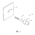
- the following description relates to a type of pre-assembled nut plate having a captured, cold-expansion mandrel and a floating nut member.
- the description further relates to a type of pre-assembled threaded insert having a captured, cold-expansion mandrel and a nut member fixed with a collar.
- the nut plate will be described and then a description of the threaded insert will follow.
- At least one purpose of the nut plate and/or threaded insert is to provided at least one fastening point in a structural workpiece so that an attachment bolt, for example for an accessory component, can be quickly inserted and secured into the nut plate or threaded insert.
- an attachment bolt for example for an accessory component
- nut plates and/or threaded inserts can be installed into a web of a wing box during production of an airplane. With the nut plates and/or threaded inserts already installed, a fuel pump or other device can be attached to the web later in the production cycle.
- a pre-assembled nut plate can be easily and quickly installed into an opening of a structural workpiece by pulling a captured, cold-expansion mandrel through a retainer, thus radially expanding the retainer, which is received by the opening in the structural workpiece according to one embodiment.
- a puller or installation tool is used to pull the mandrel through the retainer.
- the pre-assembled nut plate further includes a cap coupled to the retainer for sealing the opening in the structural workpiece once the nut plate is installed. Thus, there is no need to attach the cap after the retainer has been radially expanded.
- the radial expansion of the retainer creates a tight or interference fit between the pre-assembled nut plate and the structural workpiece, making the nut plate resistant to torque and/or push/pull-out.
- the radial expansion process secures the nut plate into the structural workpiece and then a standard screw or bolt may be inserted therein.
- the radial expansion process may introduce beneficial residual compressive stresses in the structural workpiece. The residual compressive stresses provide the structural workpiece with an improved resistance to fatigue cracking and may even provide some measure of crack retardation ( i.e., slowed crack growth).
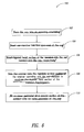
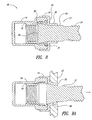
- Figure 6 is a flowchart describing a method 100 for assembling the nut plate 10 according to one illustrated embodiment.
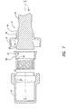
- the reader is also directed to Figures 7 and 8 to better appreciate the assembly method 100.
- the cap 16 is placed in an assembly orientation, which may be in a vertical orientation with the open end 50 of the cap 16 facing upward. However it is understood and appreciated that other assembly orientations of the cap 16 are permissible.
- the nut member 18 is inserted into the open end 50 of the cap 16. Referring briefly to Figures 7 and 8 , note that the outer profile 58 of the nut member 18 complements the inner profile 52 of the cap 16.
- the shoulder 53 of the cap 16 is configured to contact the second shoulder 62 of the nut member 18, thus permitting the nut member 18 to be inserted into the cap 16 to a certain depth.
- the nut member 18 is axially constrained between the shoulder 53 of the cap 16 and the portion 39 of the retainer 14. It is appreciated that the nut member 18 in the illustrated embodiment is free-floating, such that the nut member 18 can have at least some amount of rotation or radial displacement with respect to a centerline 64.
- One advantage of the nut member 18 being free-floating is that the nut member 18 has some play, which allows the nut member 18 to receive a later-installed fastener that may be slightly misaligned with the centerline 64 of the nut member 18.
- the tapered head section 28 of the mandrel 12 is inserted into the nut member 18 and cap 16, respectively.
- the retainer 14 is moved down the mandrel 12.
- the first section 36 of the retainer 14 is sized to fit over the engagement section 24, the shank 26, and the smaller, second outer perimeter 32, but not fit over the larger, first outer perimeter 30 of the mandrel 12.
- the tapered surface 34 is axially constrained between the nut member 18 and the retainer 14 after the retainer 14 is in place.
- the tapered surface 34 of the mandrel 12 is constrained between the first shoulder 60 of the nut member 18 and the portion 39 of the retainer 14.
- the inner perimeter 44 of the second section 38 of the retainer 14 is fit over the first outer perimeter 46 of the cap 16. It is appreciated that there are a variety of methods of fitting the retainer onto the cap and it is understood that any of these methods can be utilized to achieve a secure fit between the retainer 14 and the cap 16.
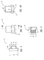
- Figures 9A - 9D illustrate the installation of the nut plate 10 into the opening 20 of the structural workpiece 22.
- the engagement section 24 of the mandrel 12, the shank 26 of the mandrel 12, and the first section 36 of the retainer 14 are placed into the opening 20 of the structural workpiece 22 such that the outer perimeter of the first section 36 is closely received by the opening 20.
- Figure 9A illustrates the tapered head section 28 of the mandrel 12 beginning to be pulled through the first section 36 of the retainer 14.
- the material of the first section 36 of the retainer 14 is radially displaced into the material of the structural workpiece 22 that defines the opening 20.
- the tapered head section 28 cold works the first section 36 of the retainer 14 and may further cold work the material of the structural workpiece 22 to provide a fatigue benefit by creating compressive, residual stresses in the material surrounding and/or adjacent to the opening 20.
- Figure 9B shows the tapered head section 28 progressing through the retainer 14 and opening 20, respectively. It is appreciated that forcibly pulling the mandrel 12 through the retainer 14 and the opening 20 can plastically increase the respective perimeters of these components where they have been cold worked.
- Figure 9C shows the tapered head section 28 of the mandrel 12 clearing the opening 20.
- the mandrel 12 can be reused or disposed. If reused, the mandrel 12 could be returned to a manufacturer to be re-assembled into another nut plate 10. The manufacturer of the nut plate 10 may or may not provide a refund or other incentive to encourage the return of the mandrels 12.
- Figure 9D shows a bolt 66 having external threads being inserted into the nut plate 10, after the nut plate 10 is installed into the opening 20 of the structural workpiece 22.
- the cap 16 seals the opening 20 in the structural workpiece 22 even if there is no bolt 66 inserted into the nut member 18. This inhibits or prevents debris from entering the sealed side of the structural workpiece, which would otherwise require tedious and time-consuming cleaning.
- Another advantage is that the cap 16 is pre-assembled with the nut member 18 and retainer 14, which eliminates the act of placing a cap over the opening 20 after the installation of the nut plate 10, which makes the installation process fast and efficient, and reduces the overall number of parts. This may be a substantial savings, particularly where hundreds, or even thousands, of nut plates 10 are installed, for example on a commercial airliner.
- Yet another advantage is a redundant and robust seal developed by the fit between the cap 16 and the retainer 14 in conjunction with the radial expansion of the first section 36 of the retainer 14 in the opening 20 of the structural workpiece.
- the redundancy and robustness of the seal is due in part because of an interference fit between the cap 16 and the retainer 14.
- the closed end 48 of the cap 16 can be located far enough from the first inner perimeter 54 of the nut member 18 to allow fasteners (e.g ., screws, bolts, etc.) of varying grip lengths to be used in the installed nut plate 10.
- the nut plate 10 weighs approximately one-third less than other known nut plates and/or threaded inserts. This weight reduction is particularly important in many industries, especially the aerospace industry.
- Figure 10 shows a sealed, nut plate 100 having a mandrel 112, a retainer 114, a cap 116, and a nut member 118.
- the components of the nut plate 100 with the exception of the nut member 118, are structurally and functionally similar to their counterpart components described in the original embodiment herein. Thus in the interest of brevity, the structurally and functionally similar components will not be described in detail.
- an inner perimeter 120 of the nut member 118 can be circular, elliptical, or some other shape.
- the inner perimeter 120 of the nut member 118 is smooth or may have a customized profile to receive a non-threaded device.
- the inner perimeter 120 of the nut member 118 can form a close and/or interference fit with a rod, a shaft, bushing, bearing, or some other structural/mechanical device.
- the nut member 118 may be resiliently, radially expandable to permit the non-threaded device, for example, to be press fit into the nut member 18.
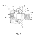
- Figure 11 shows a non-sealed nut plate 200 having a mandrel 212, a retainer 214, a collar 216, and a nut member 218 installed into the opening 20 of the structural workpiece 22 according to the illustrated embodiment.
- the components of the nut plate 200 with the exception of the collar 216, are structurally and functionally similar to as their counterpart components described in the original embodiment herein. Thus in the interest of brevity, the structurally and functionally similar components will not be described in detail.
- the collar 216 includes a first open end 248 and a second open end 250. Accordingly, the collar 216 does not seal the opening 20.
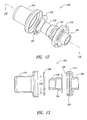
- Figures 12-14 show a nut plate 300 having a mandrel 312, a retainer 314, a cap 316, a nut member 318, and a retaining ring 320 according to the illustrated embodiment.
- a nut plate 300 having a mandrel 312, a retainer 314, a cap 316, a nut member 318, and a retaining ring 320 according to the illustrated embodiment.
- the nut member 318 includes a non-circular end section 322.
- the retainer 314 includes a plurality of notches 324 formed to receive the non-circular end section 322 of the nut member 318.
- the notches 324 operate with the end section 322 of the nut member 318 to limit or prevent the nut member 318 from rotating, especially when a fastener is later threaded into the nut member 318.
- the retainer 314 further includes a groove 326, which is best seen in Figure 13 , to receive the retaining ring 320.
- the retaining ring 320 includes an inner diameter 328 sized to operate with the retainer 314 to capture the end section 322 of the nut member 318 between a first surface 330 of the retainer 314 and the retaining ring 320 as best seen in Figure 14 .
- the retaining ring 320 includes a slot 332 ( Figure 12 ) which permits the retaining ring 320 to be adjustably sized for insertion or removal from the groove 326 formed in the retainer 314.
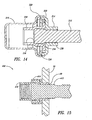
- Figure 14 shows the nut plate 300 with a tapered head section 334 of mandrel 312 in the nut member 318 and captured between a first shoulder 336 of the nut member 318 and the retainer 314. Similar to the previously described embodiments, the tapered head section 334 of the mandrel 312 is forcibly pulled through the retainer 314 to radially expand a first section 338 of the retainer 314.
- Figure 15 shows a non-sealed threaded insert 400 having a mandrel 412, a retainer 414, and a nut member 418 installed into the opening 20 of the structural workpiece 22 according to the illustrated embodiment.
- the components of the threaded insert 400 are structurally and functionally similar to their counterpart components described in the original embodiment herein. Thus in the interest of brevity, the structurally and functionally similar components will not be described in detail.
- the cap 16, 116, or collar 216 is eliminated.
- the nut member 418 includes an outer perimeter 419 sized to form an interference fit with an inner perimeter 421 of the retainer 414.
- the nut member 418 is internally threaded for receiving an externally threaded fastener at a later time. It is understood that a bonding agent may be used between the interface of the retainer 414 and the nut member 418.
- Figure 17 shows a sealed threaded insert 500 having a mandrel 512, a retainer 514, and a nut member 518 installed into the opening 20 of the structural workpiece 22 according to the illustrated embodiment.
- the present embodiment is similar to the previously described embodiment with the exception that the nut member 518 includes a closed end 519.
- the closed end 519 seals the opening 20, similar to the way the cap 16, 116, described above, sealed the opening 20.
Landscapes
- Engineering & Computer Science (AREA)
- General Engineering & Computer Science (AREA)
- Mechanical Engineering (AREA)
- Dowels (AREA)
- Flanged Joints, Insulating Joints, And Other Joints (AREA)
- Measuring Pulse, Heart Rate, Blood Pressure Or Blood Flow (AREA)
- Paper (AREA)
- Insertion Pins And Rivets (AREA)
Claims (8)
- Dispositif de fixation pouvant être installé dans une ouverture d'une pièce à travailler structurelle (22) via un outil de travail, le dispositif de fixation comprenant :un mandrin allongé (12) présentant une première extrémité, une seconde extrémité opposée à la première extrémité, une section de tête (28) formée à proximité de la première extrémité, et une section d'engagement (24) formée à proximité de la seconde extrémité, au moins une portion de la section de tête (28) présentant un périmètre externe conique formé par un premier périmètre (30) se rétrécissant jusqu'à un second périmètre (32), et dans lequel la section d'engagement peut être engagée de manière sélective par l'outil de travail,un élément écrou (18) présentant un passage formé à l'intérieur de celui-ci, le passage incluant une première section et une seconde section, le passage présentant un premier périmètre interne (54) et un second périmètre interne, la première section présentant le premier périmètre interne (54), la seconde section présentant le second périmètre interne qui est plus large que le premier périmètre interne (54), dans lequel une transition entre le premier périmètre interne (54) et le second périmètre interne forme un épaulement de l'élément écrou (60), etun arrêtoir (14) présentant une première section (36) et une seconde section (38), qui sont connectées par une portion (39), la première section (36) de l'arrêtoir (14) comprenant un périmètre interne (40) dont la taille est faite pour être légèrement inférieure au premier périmètre (30) de la section de tête du mandrin caractérisé en ce que la portion (39) de l'arrêtoir (14) coopère avec l'élément écrou (18) afin de capturer la
section de tête (28) du mandrin (12) sensiblement entre l'épaulement de l'élément écrou (60) et la portion (39) de l'arrêtoir (14) de telle sorte qu'au moins une portion de la section de tête (28) présentant le premier périmètre (30) se trouve dans la seconde section (38) du passage jusqu'à ce que le mandrin (12) soit retiré de force de l'arrêtoir (14). - Dispositif de fixation selon la revendication 1, comprenant en outre : un capuchon (16) présentant une extrémité ouverte (50) et une extrémité fermée (48), l'extrémité ouverte (50) présentant un périmètre externe (46) et périmètre interne, le périmètre externe (46) présentant une taille telle qu'il peut être étroitement reçu dans la seconde section (38) de l'arrêtoir (14), le périmètre interne de l'extrémité ouverte présentant une taille telle qu'il reçoit largement l'élément écrou (18).
- Dispositif de fixation selon la revendication 1, dans lequel au moins une portion du premier périmètre interne de la première section de l'élément écrou (18) est filetée.
- Dispositif de fixation selon la revendication 1, dans lequel au moins une portion du premier périmètre interne de la première section de l'élément écrou (18) est dépourvue de filetage.
- Dispositif de fixation selon la revendication 1, dans lequel la section d'engagement (24) du mandrin (12) est filetée.
- Procédé de fixation du dispositif de fixation selon la revendication 2, le procédé comprenant des étapes consistant à : insérer l'élément écrou (18) dans une extrémité ouverte d'un capuchon (16), l'élément écrou (18) étant contraint axialement dans une première direction par une portion du capuchon (16), insérer la section de tête (28) du mandrin (12) au moins partiellement dans la seconde section de l'élément écrou (18), une portion allongée du mandrin (12) s'étendant depuis la section de tête (28) du mandrin (12), et puis engager un périmètre interne de la seconde section (38) de l'arrêtoir (14) avec un périmètre externe du capuchon (16), le périmètre interne (40) de la première section (36) de l'arrêtoir (14) présentant une taille telle qu'il maintient au moins une portion de la section de tête (28) du mandrin (12) présentant le premier périmètre sensiblement dans la seconde section du passage de l'élément écrou (18) jusqu'à ce que le mandrin (12) soit retiré de force de l'arrêtoir (14).
- Procédé selon la revendication 6, dans lequel l'étape consistant à engager le périmètre interne de la seconde section (38) de l'arrêtoir (14) avec le périmètre externe du capuchon (16) comprend une étape consistant à former un ajustement avec serrage entre le périmètre interne de la seconde section (38) de l'arrêtoir (14) et le périmètre externe du capuchon (16).
- Procédé selon la revendication 6, dans lequel l'étape consistant à insérer la section de tête conique (28) du mandrin (12) au moins partiellement dans l'élément écrou (18) comprend une étape consistant à faire entrer en contact la section de tête conique (28) avec l'épaulement (60) de l'élément écrou (18).
Applications Claiming Priority (2)
| Application Number | Priority Date | Filing Date | Title |
|---|---|---|---|
| US68722805P | 2005-06-03 | 2005-06-03 | |
| PCT/US2006/021351 WO2006132936A1 (fr) | 2005-06-03 | 2006-06-02 | Plaques d'ecrous et elements d'insertion filetes et leurs procedes d'assemblage et d'installation |
Publications (2)
| Publication Number | Publication Date |
|---|---|
| EP1893875A1 EP1893875A1 (fr) | 2008-03-05 |
| EP1893875B1 true EP1893875B1 (fr) | 2011-03-02 |
Family
ID=36997812
Family Applications (1)
| Application Number | Title | Priority Date | Filing Date |
|---|---|---|---|
| EP06771882A Active EP1893875B1 (fr) | 2005-06-03 | 2006-06-02 | Dispositif de fixation et procédé pour son assemblage |
Country Status (5)
| Country | Link |
|---|---|
| US (1) | US7641430B2 (fr) |
| EP (1) | EP1893875B1 (fr) |
| AT (1) | ATE500431T1 (fr) |
| DE (1) | DE602006020443D1 (fr) |
| WO (1) | WO2006132936A1 (fr) |
Cited By (4)
| Publication number | Priority date | Publication date | Assignee | Title |
|---|---|---|---|---|
| US8763229B2 (en) | 2011-06-03 | 2014-07-01 | Fatigue Technology, Inc. | Expandable crack inhibitor method |
| US8938886B2 (en) | 2012-01-30 | 2015-01-27 | Fatigue Technology, Inc. | Smart installation/processing systems, components, and methods of operating the same |
| US9114449B2 (en) | 2011-06-15 | 2015-08-25 | Fatigue Technology, Inc. | Modular nut plates with closed nut assemblies |
| US10010983B2 (en) | 2008-03-07 | 2018-07-03 | Fatigue Technology, Inc. | Expandable member with wave inhibitor and methods of using the same |
Families Citing this family (21)
| Publication number | Priority date | Publication date | Assignee | Title |
|---|---|---|---|---|
| US20070110541A1 (en) * | 2005-10-28 | 2007-05-17 | Fatigue Technology, Inc. | Radially displaceable bushing for retaining a member relative to a structural workpiece |
| US7509829B2 (en) | 2005-12-28 | 2009-03-31 | Fatigue Technology, Inc. | Mandrel assembly and method of using the same |
| WO2007082077A1 (fr) * | 2006-01-11 | 2007-07-19 | Fatigue Technology, Inc. | Kits de coussinets, paliers, et procédés d’installation |
| ATE536957T1 (de) | 2006-04-27 | 2011-12-15 | Fatigue Technology Inc | Ausrichtungsvorrichtung und anwendungsverfahren |
| EP2158409A2 (fr) * | 2007-05-15 | 2010-03-03 | Fatigue Technology, Inc. | Collier extensible installé en aveugle et élément interne fileté |
| WO2010009442A2 (fr) | 2008-07-18 | 2010-01-21 | Fatigue Technology, Inc. | Ensemble plaque à écrou et procédés d'utilisation de celui-ci |
| EP2417369B1 (fr) | 2009-04-10 | 2014-04-02 | Fatigue Technology, Inc. | Ensemble installable avec manchon extensible et un élément de fixation avec mandrin de traction |
| US8647035B2 (en) | 2009-12-16 | 2014-02-11 | Fatigue Technology, Inc. | Modular nut plate assemblies and methods of using the same |
| KR101052583B1 (ko) | 2011-01-31 | 2011-07-28 | (주)하이드로훼스트 | 어댑터식 유압인장너트 |
| US8734075B1 (en) * | 2012-01-25 | 2014-05-27 | Mark Hamilton King | Sheared pole butt removal tool |
| US10179640B2 (en) * | 2016-08-24 | 2019-01-15 | The Boeing Company | Wing and method of manufacturing |
| EP3685055A4 (fr) * | 2017-09-22 | 2021-11-10 | Partworks, LLC | Outil de fixation sans rivet et outil d'installation |
| CN107906109A (zh) * | 2017-12-14 | 2018-04-13 | 天津成立航空技术有限公司 | 一种用于飞机机体的高密封快卸螺母 |
| US10899083B1 (en) * | 2018-03-29 | 2021-01-26 | Kineticure, Llc | Bonded nutplate rapid cure system |
| NO348356B1 (no) * | 2018-11-23 | 2024-12-02 | Bondura Tech As | Arrangement for sikring av en mutter |
| CN109578411A (zh) * | 2018-12-07 | 2019-04-05 | 西安飞机工业(集团)有限责任公司 | 一种金属罩单耳密封游动自锁螺母 |
| US11268562B2 (en) * | 2019-08-12 | 2022-03-08 | The Boeing Company | Nut plate assembly |
| EP3862584B1 (fr) * | 2020-02-06 | 2025-05-14 | BBA S.r.l. | Composant de fixation comportant un rivet borgne et un élément d'étanchéité |
| DE102020006613A1 (de) * | 2020-10-28 | 2022-04-28 | RB&W GmbH | Verfahren zum Herstellen einer Verbindung zwischen einem Einpresselement und einer plastisch verformbaren Durchgangsöffnung in einer Wandung eines Hohlprofils |
| US12304153B1 (en) | 2022-08-30 | 2025-05-20 | Kineticure, Llc | Bonded nutplate rapid cure system with fixtured heater |
| US12365146B1 (en) | 2022-08-30 | 2025-07-22 | Kineticure, Llc | Bonded nutplate rapid cure system with fixtured heater |
Family Cites Families (11)
| Publication number | Priority date | Publication date | Assignee | Title |
|---|---|---|---|---|
| US3698278A (en) * | 1971-03-15 | 1972-10-17 | Vsi Corp | Nut member |
| US4295766A (en) * | 1978-07-27 | 1981-10-20 | Francis Shaw | Self-aligning dome nut |
| US5245743A (en) * | 1990-07-26 | 1993-09-21 | Fatigue Technology, Inc. | Method of installing a nut mounting grommet |
| US5135340A (en) * | 1991-04-10 | 1992-08-04 | Hi-Shear Corporation | Bulged and swelled blind fastener |
| US5704747A (en) * | 1996-07-16 | 1998-01-06 | Physical Systems, Inc. A Nevada Corp. | Adhesive bonded nutplate assembly with integral liner sleeve |
| US6592314B1 (en) * | 2000-10-10 | 2003-07-15 | Industrial And Automotive Fasteners, Llc | Steel washer integral with nut/cap assembly |
| US7237614B2 (en) * | 2001-08-15 | 2007-07-03 | Stewart Hitchon | Potable well conversion device |
| US7059816B2 (en) * | 2001-11-09 | 2006-06-13 | Textron Inc. | Nut plate |
| US7114900B2 (en) * | 2001-11-09 | 2006-10-03 | Textron Inc. | Push-type rivetless nut plate and method and apparatus for installing same |
| US8057144B2 (en) * | 2004-08-27 | 2011-11-15 | Fatigue Technology, Inc. | Sealed, blind fastener assembly |
| US20060078399A1 (en) | 2004-10-13 | 2006-04-13 | Fatigue Technology, Inc. | Blindly installed, reinforceable nuts for joining structural members |
-
2006
- 2006-06-02 WO PCT/US2006/021351 patent/WO2006132936A1/fr not_active Ceased
- 2006-06-02 US US11/445,951 patent/US7641430B2/en active Active
- 2006-06-02 EP EP06771882A patent/EP1893875B1/fr active Active
- 2006-06-02 AT AT06771882T patent/ATE500431T1/de not_active IP Right Cessation
- 2006-06-02 DE DE602006020443T patent/DE602006020443D1/de active Active
Cited By (6)
| Publication number | Priority date | Publication date | Assignee | Title |
|---|---|---|---|---|
| US10010983B2 (en) | 2008-03-07 | 2018-07-03 | Fatigue Technology, Inc. | Expandable member with wave inhibitor and methods of using the same |
| US8763229B2 (en) | 2011-06-03 | 2014-07-01 | Fatigue Technology, Inc. | Expandable crack inhibitor method |
| US9114449B2 (en) | 2011-06-15 | 2015-08-25 | Fatigue Technology, Inc. | Modular nut plates with closed nut assemblies |
| US8938886B2 (en) | 2012-01-30 | 2015-01-27 | Fatigue Technology, Inc. | Smart installation/processing systems, components, and methods of operating the same |
| US10130985B2 (en) | 2012-01-30 | 2018-11-20 | Fatigue Technology, Inc. | Smart installation/processing systems, components, and methods of operating the same |
| US10843250B2 (en) | 2012-01-30 | 2020-11-24 | Fatigue Technology, Inc. | Smart installation/processing systems, components, and methods of operating the same |
Also Published As
| Publication number | Publication date |
|---|---|
| US20070048107A1 (en) | 2007-03-01 |
| WO2006132936A1 (fr) | 2006-12-14 |
| ATE500431T1 (de) | 2011-03-15 |
| DE602006020443D1 (de) | 2011-04-14 |
| EP1893875A1 (fr) | 2008-03-05 |
| US7641430B2 (en) | 2010-01-05 |
Similar Documents
| Publication | Publication Date | Title |
|---|---|---|
| EP1893875B1 (fr) | Dispositif de fixation et procédé pour son assemblage | |
| EP1803526B1 (fr) | Ensemble mandrin et procédé de son utilisation | |
| EP2019739B1 (fr) | Dispositif d'alignement et ses procédés d'utilisation | |
| JP5588039B2 (ja) | 複合材料用のナット板締結具アセンブリ | |
| US7823262B2 (en) | Method of replacing a nut plate fastener assembly | |
| US20030118419A1 (en) | Method for installation of nut plates, plugs, and bushings, and enhanced fatigue life metal structures resulting therefrom | |
| US20070289351A1 (en) | Wave relieving geometric features in structural members that are radially expandable into workpieces | |
| EP0331775A1 (fr) | Rivet aveugle pour matériau composite | |
| JP2005518509A (ja) | ハニカムリベット | |
| US20060075617A1 (en) | Performance enhancing repair tool | |
| US4767248A (en) | Fastener for securing panels of composite materials | |
| US20110038688A1 (en) | Blind installed expandable collar and threaded inner member | |
| US20060078399A1 (en) | Blindly installed, reinforceable nuts for joining structural members | |
| EP4148287B1 (fr) | Fixations en aveugle et procédés associés permettant d'installer des fixations en aveugle | |
| EP3921552B1 (fr) | Élément de fixation aveugle et son procédé d'installation | |
| EP0728950A1 (fr) | Procédé pour la fixation de deux éléments et dispositif de fixation associé |
Legal Events
| Date | Code | Title | Description |
|---|---|---|---|
| PUAI | Public reference made under article 153(3) epc to a published international application that has entered the european phase |
Free format text: ORIGINAL CODE: 0009012 |
|
| 17P | Request for examination filed |
Effective date: 20080102 |
|
| AK | Designated contracting states |
Kind code of ref document: A1 Designated state(s): AT BE BG CH CY CZ DE DK EE ES FI FR GB GR HU IE IS IT LI LT LU LV MC NL PL PT RO SE SI SK TR |
|
| 17Q | First examination report despatched |
Effective date: 20080325 |
|
| DAX | Request for extension of the european patent (deleted) | ||
| GRAP | Despatch of communication of intention to grant a patent |
Free format text: ORIGINAL CODE: EPIDOSNIGR1 |
|
| RTI1 | Title (correction) |
Free format text: FASTENER ASSEMBLY AND METHOD OF ASSEMBLING THE SAME |
|
| GRAS | Grant fee paid |
Free format text: ORIGINAL CODE: EPIDOSNIGR3 |
|
| GRAA | (expected) grant |
Free format text: ORIGINAL CODE: 0009210 |
|
| AK | Designated contracting states |
Kind code of ref document: B1 Designated state(s): AT BE BG CH CY CZ DE DK EE ES FI FR GB GR HU IE IS IT LI LT LU LV MC NL PL PT RO SE SI SK TR |
|
| REG | Reference to a national code |
Ref country code: GB Ref legal event code: FG4D |
|
| REG | Reference to a national code |
Ref country code: CH Ref legal event code: EP |
|
| REG | Reference to a national code |
Ref country code: IE Ref legal event code: FG4D |
|
| REF | Corresponds to: |
Ref document number: 602006020443 Country of ref document: DE Date of ref document: 20110414 Kind code of ref document: P |
|
| REG | Reference to a national code |
Ref country code: DE Ref legal event code: R096 Ref document number: 602006020443 Country of ref document: DE Effective date: 20110414 |
|
| REG | Reference to a national code |
Ref country code: NL Ref legal event code: VDEP Effective date: 20110302 |
|
| PG25 | Lapsed in a contracting state [announced via postgrant information from national office to epo] |
Ref country code: LV Free format text: LAPSE BECAUSE OF FAILURE TO SUBMIT A TRANSLATION OF THE DESCRIPTION OR TO PAY THE FEE WITHIN THE PRESCRIBED TIME-LIMIT Effective date: 20110302 Ref country code: GR Free format text: LAPSE BECAUSE OF FAILURE TO SUBMIT A TRANSLATION OF THE DESCRIPTION OR TO PAY THE FEE WITHIN THE PRESCRIBED TIME-LIMIT Effective date: 20110603 Ref country code: LT Free format text: LAPSE BECAUSE OF FAILURE TO SUBMIT A TRANSLATION OF THE DESCRIPTION OR TO PAY THE FEE WITHIN THE PRESCRIBED TIME-LIMIT Effective date: 20110302 Ref country code: SE Free format text: LAPSE BECAUSE OF FAILURE TO SUBMIT A TRANSLATION OF THE DESCRIPTION OR TO PAY THE FEE WITHIN THE PRESCRIBED TIME-LIMIT Effective date: 20110302 Ref country code: ES Free format text: LAPSE BECAUSE OF FAILURE TO SUBMIT A TRANSLATION OF THE DESCRIPTION OR TO PAY THE FEE WITHIN THE PRESCRIBED TIME-LIMIT Effective date: 20110613 |
|
| LTIE | Lt: invalidation of european patent or patent extension |
Effective date: 20110302 |
|
| PG25 | Lapsed in a contracting state [announced via postgrant information from national office to epo] |
Ref country code: SI Free format text: LAPSE BECAUSE OF FAILURE TO SUBMIT A TRANSLATION OF THE DESCRIPTION OR TO PAY THE FEE WITHIN THE PRESCRIBED TIME-LIMIT Effective date: 20110302 Ref country code: FI Free format text: LAPSE BECAUSE OF FAILURE TO SUBMIT A TRANSLATION OF THE DESCRIPTION OR TO PAY THE FEE WITHIN THE PRESCRIBED TIME-LIMIT Effective date: 20110302 Ref country code: BG Free format text: LAPSE BECAUSE OF FAILURE TO SUBMIT A TRANSLATION OF THE DESCRIPTION OR TO PAY THE FEE WITHIN THE PRESCRIBED TIME-LIMIT Effective date: 20110602 Ref country code: NL Free format text: LAPSE BECAUSE OF FAILURE TO SUBMIT A TRANSLATION OF THE DESCRIPTION OR TO PAY THE FEE WITHIN THE PRESCRIBED TIME-LIMIT Effective date: 20110302 Ref country code: CY Free format text: LAPSE BECAUSE OF FAILURE TO SUBMIT A TRANSLATION OF THE DESCRIPTION OR TO PAY THE FEE WITHIN THE PRESCRIBED TIME-LIMIT Effective date: 20110302 Ref country code: AT Free format text: LAPSE BECAUSE OF FAILURE TO SUBMIT A TRANSLATION OF THE DESCRIPTION OR TO PAY THE FEE WITHIN THE PRESCRIBED TIME-LIMIT Effective date: 20110302 |
|
| PG25 | Lapsed in a contracting state [announced via postgrant information from national office to epo] |
Ref country code: BE Free format text: LAPSE BECAUSE OF FAILURE TO SUBMIT A TRANSLATION OF THE DESCRIPTION OR TO PAY THE FEE WITHIN THE PRESCRIBED TIME-LIMIT Effective date: 20110302 |
|
| PG25 | Lapsed in a contracting state [announced via postgrant information from national office to epo] |
Ref country code: EE Free format text: LAPSE BECAUSE OF FAILURE TO SUBMIT A TRANSLATION OF THE DESCRIPTION OR TO PAY THE FEE WITHIN THE PRESCRIBED TIME-LIMIT Effective date: 20110302 Ref country code: PT Free format text: LAPSE BECAUSE OF FAILURE TO SUBMIT A TRANSLATION OF THE DESCRIPTION OR TO PAY THE FEE WITHIN THE PRESCRIBED TIME-LIMIT Effective date: 20110704 |
|
| PG25 | Lapsed in a contracting state [announced via postgrant information from national office to epo] |
Ref country code: IS Free format text: LAPSE BECAUSE OF FAILURE TO SUBMIT A TRANSLATION OF THE DESCRIPTION OR TO PAY THE FEE WITHIN THE PRESCRIBED TIME-LIMIT Effective date: 20110702 Ref country code: SK Free format text: LAPSE BECAUSE OF FAILURE TO SUBMIT A TRANSLATION OF THE DESCRIPTION OR TO PAY THE FEE WITHIN THE PRESCRIBED TIME-LIMIT Effective date: 20110302 Ref country code: RO Free format text: LAPSE BECAUSE OF FAILURE TO SUBMIT A TRANSLATION OF THE DESCRIPTION OR TO PAY THE FEE WITHIN THE PRESCRIBED TIME-LIMIT Effective date: 20110302 Ref country code: CZ Free format text: LAPSE BECAUSE OF FAILURE TO SUBMIT A TRANSLATION OF THE DESCRIPTION OR TO PAY THE FEE WITHIN THE PRESCRIBED TIME-LIMIT Effective date: 20110302 |
|
| PLBE | No opposition filed within time limit |
Free format text: ORIGINAL CODE: 0009261 |
|
| STAA | Information on the status of an ep patent application or granted ep patent |
Free format text: STATUS: NO OPPOSITION FILED WITHIN TIME LIMIT |
|
| REG | Reference to a national code |
Ref country code: CH Ref legal event code: PL |
|
| 26N | No opposition filed |
Effective date: 20111205 |
|
| PG25 | Lapsed in a contracting state [announced via postgrant information from national office to epo] |
Ref country code: PL Free format text: LAPSE BECAUSE OF FAILURE TO SUBMIT A TRANSLATION OF THE DESCRIPTION OR TO PAY THE FEE WITHIN THE PRESCRIBED TIME-LIMIT Effective date: 20110302 Ref country code: DK Free format text: LAPSE BECAUSE OF FAILURE TO SUBMIT A TRANSLATION OF THE DESCRIPTION OR TO PAY THE FEE WITHIN THE PRESCRIBED TIME-LIMIT Effective date: 20110302 |
|
| REG | Reference to a national code |
Ref country code: IE Ref legal event code: MM4A |
|
| REG | Reference to a national code |
Ref country code: DE Ref legal event code: R097 Ref document number: 602006020443 Country of ref document: DE Effective date: 20111205 |
|
| PG25 | Lapsed in a contracting state [announced via postgrant information from national office to epo] |
Ref country code: LI Free format text: LAPSE BECAUSE OF NON-PAYMENT OF DUE FEES Effective date: 20110630 Ref country code: CH Free format text: LAPSE BECAUSE OF NON-PAYMENT OF DUE FEES Effective date: 20110630 Ref country code: IE Free format text: LAPSE BECAUSE OF NON-PAYMENT OF DUE FEES Effective date: 20110602 |
|
| PG25 | Lapsed in a contracting state [announced via postgrant information from national office to epo] |
Ref country code: IT Free format text: LAPSE BECAUSE OF FAILURE TO SUBMIT A TRANSLATION OF THE DESCRIPTION OR TO PAY THE FEE WITHIN THE PRESCRIBED TIME-LIMIT Effective date: 20110302 |
|
| PG25 | Lapsed in a contracting state [announced via postgrant information from national office to epo] |
Ref country code: MC Free format text: LAPSE BECAUSE OF NON-PAYMENT OF DUE FEES Effective date: 20110630 |
|
| PG25 | Lapsed in a contracting state [announced via postgrant information from national office to epo] |
Ref country code: LU Free format text: LAPSE BECAUSE OF NON-PAYMENT OF DUE FEES Effective date: 20110602 |
|
| PG25 | Lapsed in a contracting state [announced via postgrant information from national office to epo] |
Ref country code: TR Free format text: LAPSE BECAUSE OF FAILURE TO SUBMIT A TRANSLATION OF THE DESCRIPTION OR TO PAY THE FEE WITHIN THE PRESCRIBED TIME-LIMIT Effective date: 20110302 |
|
| PG25 | Lapsed in a contracting state [announced via postgrant information from national office to epo] |
Ref country code: HU Free format text: LAPSE BECAUSE OF FAILURE TO SUBMIT A TRANSLATION OF THE DESCRIPTION OR TO PAY THE FEE WITHIN THE PRESCRIBED TIME-LIMIT Effective date: 20110302 |
|
| REG | Reference to a national code |
Ref country code: FR Ref legal event code: PLFP Year of fee payment: 10 |
|
| REG | Reference to a national code |
Ref country code: FR Ref legal event code: PLFP Year of fee payment: 11 |
|
| REG | Reference to a national code |
Ref country code: FR Ref legal event code: PLFP Year of fee payment: 12 |
|
| REG | Reference to a national code |
Ref country code: FR Ref legal event code: PLFP Year of fee payment: 13 |
|
| PGFP | Annual fee paid to national office [announced via postgrant information from national office to epo] |
Ref country code: DE Payment date: 20250429 Year of fee payment: 20 |
|
| PGFP | Annual fee paid to national office [announced via postgrant information from national office to epo] |
Ref country code: GB Payment date: 20250501 Year of fee payment: 20 |
|
| PGFP | Annual fee paid to national office [announced via postgrant information from national office to epo] |
Ref country code: FR Payment date: 20250508 Year of fee payment: 20 |