EP1893882B1 - Frein a disque dote de dispositifs de rattrapage de jeu actionnes par un moteur electrique et procede de production d'un frein de stationnement - Google Patents
Frein a disque dote de dispositifs de rattrapage de jeu actionnes par un moteur electrique et procede de production d'un frein de stationnement Download PDFInfo
- Publication number
- EP1893882B1 EP1893882B1 EP06754354.6A EP06754354A EP1893882B1 EP 1893882 B1 EP1893882 B1 EP 1893882B1 EP 06754354 A EP06754354 A EP 06754354A EP 1893882 B1 EP1893882 B1 EP 1893882B1
- Authority
- EP
- European Patent Office
- Prior art keywords
- brake
- disc
- adjusting
- stop
- disc brake
- Prior art date
- Legal status (The legal status is an assumption and is not a legal conclusion. Google has not performed a legal analysis and makes no representation as to the accuracy of the status listed.)
- Expired - Lifetime
Links
Images


Classifications
-
- F—MECHANICAL ENGINEERING; LIGHTING; HEATING; WEAPONS; BLASTING
- F16—ENGINEERING ELEMENTS AND UNITS; GENERAL MEASURES FOR PRODUCING AND MAINTAINING EFFECTIVE FUNCTIONING OF MACHINES OR INSTALLATIONS; THERMAL INSULATION IN GENERAL
- F16D—COUPLINGS FOR TRANSMITTING ROTATION; CLUTCHES; BRAKES
- F16D65/00—Parts or details
- F16D65/14—Actuating mechanisms for brakes; Means for initiating operation at a predetermined position
- F16D65/16—Actuating mechanisms for brakes; Means for initiating operation at a predetermined position arranged in or on the brake
- F16D65/18—Actuating mechanisms for brakes; Means for initiating operation at a predetermined position arranged in or on the brake adapted for drawing members together, e.g. for disc brakes
- F16D65/183—Actuating mechanisms for brakes; Means for initiating operation at a predetermined position arranged in or on the brake adapted for drawing members together, e.g. for disc brakes with force-transmitting members arranged side by side acting on a spot type force-applying member
-
- F—MECHANICAL ENGINEERING; LIGHTING; HEATING; WEAPONS; BLASTING
- F16—ENGINEERING ELEMENTS AND UNITS; GENERAL MEASURES FOR PRODUCING AND MAINTAINING EFFECTIVE FUNCTIONING OF MACHINES OR INSTALLATIONS; THERMAL INSULATION IN GENERAL
- F16D—COUPLINGS FOR TRANSMITTING ROTATION; CLUTCHES; BRAKES
- F16D65/00—Parts or details
- F16D65/38—Slack adjusters
- F16D2065/386—Slack adjusters driven electrically
-
- F—MECHANICAL ENGINEERING; LIGHTING; HEATING; WEAPONS; BLASTING
- F16—ENGINEERING ELEMENTS AND UNITS; GENERAL MEASURES FOR PRODUCING AND MAINTAINING EFFECTIVE FUNCTIONING OF MACHINES OR INSTALLATIONS; THERMAL INSULATION IN GENERAL
- F16D—COUPLINGS FOR TRANSMITTING ROTATION; CLUTCHES; BRAKES
- F16D2121/00—Type of actuator operation force
- F16D2121/02—Fluid pressure
-
- F—MECHANICAL ENGINEERING; LIGHTING; HEATING; WEAPONS; BLASTING
- F16—ENGINEERING ELEMENTS AND UNITS; GENERAL MEASURES FOR PRODUCING AND MAINTAINING EFFECTIVE FUNCTIONING OF MACHINES OR INSTALLATIONS; THERMAL INSULATION IN GENERAL
- F16D—COUPLINGS FOR TRANSMITTING ROTATION; CLUTCHES; BRAKES
- F16D2125/00—Components of actuators
- F16D2125/18—Mechanical mechanisms
- F16D2125/58—Mechanical mechanisms transmitting linear movement
- F16D2125/64—Levers
-
- F—MECHANICAL ENGINEERING; LIGHTING; HEATING; WEAPONS; BLASTING
- F16—ENGINEERING ELEMENTS AND UNITS; GENERAL MEASURES FOR PRODUCING AND MAINTAINING EFFECTIVE FUNCTIONING OF MACHINES OR INSTALLATIONS; THERMAL INSULATION IN GENERAL
- F16D—COUPLINGS FOR TRANSMITTING ROTATION; CLUTCHES; BRAKES
- F16D2127/00—Auxiliary mechanisms
- F16D2127/06—Locking mechanisms, e.g. acting on actuators, on release mechanisms or on force transmission mechanisms
Definitions
- the invention relates to a disc brake with electric motor-operated adjusting devices according to the preamble of claim 1 and a method for performing a parking brake with such a disc brake.
- Generic disc brakes are known per se, so from the PCT / EP01 / 09370
- the brake is applied by a brake application device, which is actuated by a pneumatically actuated actuator.
- This actuator may be a spring brake cylinder or a service brake cylinder.
- the parking brake effect is usually realized in heavy commercial vehicles with compressed air brake system by the spring brake cylinder.
- the spring-loaded cylinder acts in the parking brake case with the force of its accumulator spring on the actuator of the wheel and generates in this way the necessary holding force.
- the accumulator spring In the activated state, the accumulator spring is biased by a pressurized piston so far that no force is released from this spring on the actuator of the brake and the vehicle is released for free running.
- the existing service brake is also used as a parking brake. It is also very robust and can be executed very reliably.
- a disadvantage is the very large space requirement and the high weight of the spring-loaded cylinder, the same high compressed air consumption and the need to build their own pressure supply circuit for the parking brake.
- the service brake actuator is thus used only to actuate the brake, the holding effect is carried out after releasing the Radio Service brake actuator exclusively mechanically.
- EP 0 526 273 A discloses a lockable disc brake, which is hydraulically actuated, but has no adjusting device to compensate for a wear-related clearance.
- the invention solves this problem by the subject of Ansprüchs. 1
- the invention realizes a disc brake, in which a parking brake function is realized by using a particularly space-saving locking mechanism, so that the disc brake according to the invention requires only a minimal amount of space, control means and costs.
- the invention assigns the adjusting piston or Nachstellitchspindeln at least one or more locking devices. This is advantageous in that the adjusting devices, which on the one hand serve as an adjusting piston when applying the brake and on the other hand just to compensate for the lining and preferably disc wear, allow a surprisingly simple and space-saving arrangement or accommodation of the locking device (s).
- This variant is particularly suitable for pneumatically actuated disc brake solved with electric motor-operated adjusting devices, as they already have a power supply for driving the Versp Dahlmuttern.
- the locking of the adjusting piston can not be done in a variant nich according to the invention instead of the rotation of Versp Schwarzmuttern by inserting or pivoting of locking elements through which the blockage of the adjusting nuts against stop surfaces on the brake caliper is effected.
- the arranged on the adjusting spindles or sleeves and serving to drive the same gears are preferably additionally used as Versp Rudmuttern.
- connection of the gears with the adjusting piston is particularly preferably designed so that the gears are screwed by a thread on the actuating piston and bear in its normal position against a stop on the actuating piston.
- the gears are preferably additionally connected to the actuating piston via a preloaded slip clutch that allows release above a certain limit torque, the limit torque is above the working range of the adjuster.
- the invention provides the possibility of realizing the parking brake function by operating the brake by means of service brake cylinder and locking the adjusting spindles - actuating piston - in the braked position by means of locking devices, preferably by the arranged on these adjusting spindles Versp Dahlmuttem.
- Another advantage is the use of the rotational inhibition occurring at the adjusting spindles in the braked state to generate a drive torque threshold for the spindle gears, below the torque threshold, the spindle gear via a torque-dependent coupling drives the spindles for performing the readjustment process and when in the braked state Blocked adjusting spindles, the spindle gear is rotated against the resistance of the torque-dependent coupling in a threaded connection to the adjusting spindle to adjust the spindle gear relative to the adjusting spindle axially and apply to the stop surface on the brake caliper.
- the torque-controlled clutch is designed as a preloaded friction clutch.
- Radial biasing of the coupling may be achieved via spring friction elements acting radially between the spindle gear and the adjusting spindle, e.g. take place in the form of a tolerance ring or a spring ring.
- a rotation of the threaded collar takes place relative to the spindle gear. This rotation can be done, for example, by the fact that the threaded collar receives on the outer circumference of the spindle gear corresponding teeth and the driving gear with both teeth simultaneously engaged.
- the integrated electronic control of the brake is activated, e.g. over an existing data bus, e.g. from the EBS, or the parking brake setpoint generator or the central vehicle computer or another vehicle system. Then took place self-sufficient operation of the locking process.
- the control of the entire parking brake operation including the loading and unloading of the service brake cylinder can be done using EBS, or ABS + ASR valve or ABS + inverse relay valve.
- Fig. 2 and 3 show a disc brake according to the prior art, which has a brake disc 1 at least in the outer peripheral region or comprehensive caliper 2.
- brake pads 3, 4 are arranged, wherein the one of the two brake pads is displaceable by means of a brake application device 5 in the direction of the brake disc 1, the. is designed as a sliding disc.
- the application-side brake lining 3 is first moved against the brake disk 1 and then the brake disk 1 is moved further against the second brake lining on the reaction side.
- the application device is usually actuated by a pneumatically actuated actuator such as a service brake cylinder BZ. Also conceivable is an actuation via an electromotive actuator.
- the axial length of the actuating piston 7 is changed, which act on one of the ends of the thrust pieces 8 on the brake pad 3 and which are supported at their opposite ends to a Zuspannelement the application device, here the rotary lever 6.
- the application-side adjusting pistons 7 on the one hand as a whole axially displaceable in order to clamp the brake and to solve them and on the other hand their length is variable to compensate for the lining and disc wear.
- the application-side adjusting pistons 7 each consist at least of a spindle 10 with an external thread and a screwed onto the spindle 10 sleeve 12 with a corresponding internal thread.
- At least one electric motor drive 9 which acts on the actuating piston via gear elements such as gears 11 to screw the sleeves 12 relative to the spindles 10 or to rotate, so that the axial length of the actuating piston 7 changed from sleeve 12 and spindle 10.
- a separate adjusting device with adjusting spindles and drive which carries the reference numeral 18 in its entirety, arranged.
- the spindle 10 is oriented towards the rotary lever 6 and the sleeve 12 to the pressure plate 8. This arrangement can also be reversed.
- the invention assigns the application-side actuating piston now in the manner of the schematic diagram of the Fig. 1 at least one or more locking devices 13 to, this allows to easily fix the position of the actuating piston during braking, for example, to carry out parking braking or "freeze” so that the brake remains in the braked state.
- a locking device for fixing the axial position of the adjusting piston is provided.
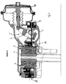
- Fig. 1 shows a portion of a schematically illustrated in section disc brake in three different operating conditions.
- the disc brake the Fig. 1 in turn has the caliper 2, which surrounds the brake disc 1 in the upper peripheral region (shown here only in sections).
- the plungers 8 act, which are guided perpendicular to the brake disc plane or parallel to the brake disc axis slidably.
- the entire adjusting pistons 7 are simply displaced in the direction of the brake disk ( Fig. 1a to Fig. 1b ), until the brake pads abut the brake disc and the braking effect occurs.
- the brake actuator e.g., the pneumatically actuated brake cylinder, the piston rod of which acts on a rotary lever disposed in the caliper so that it shifts the two thrust pads axially toward the brake disc during braking.
- the rotation of the adjusting piston for the axial length change takes place by means of an independent of the brake actuator electric motor 9, which, for. directly or via a gear connection to gears 11 e.g. acting on the outer circumference of the sleeves 12.
- the nut or sleeve of NachstellFE drove not only an internal thread, with which it is screwed onto the threaded bolt, which carries at one axial end of the pressure piece but it is screwed as a locking device a supplementary Versp Schwarzmutter 14 on an external thread 15 of the sleeve 12 whose position 12 on the sleeve, for example by means of another electric motor or by means of the electric motor 8 ( Fig. 2 ) is rotatable for the adjustment, such that the Versp Drutter 14 against an axial stop, such as a collar 17 of the caliper is movable, whereby it is possible to change the position of the actuating piston during operation and / or parking braking.
- Fig. 1 Phase 1 - Non-actuated state of the brake:
- the arranged on the adjusting sleeves 12 Versp Schwarzmuttern 14 are at a short distance below the stop surfaces of the caliper.
- the adjusting piston 7, via which the entire clamping force is transmitted, moved to overcome the clearance and the elasticities in the direction of the brake disc.
- the clamping force of the brake now acts from the brake pad 3 pressed onto the brake disk 2 via the adjuster piston 7 and the brake lever 5 and its bearing elements on the brake caliper 2.
- the reaction force compensation takes place with the opposing brake pad 4.
- the Versp Schwarzmuttern 14 have taken as a result of the displacement of the adjusting piston 7 a greater distance to the displacement of the abutment surfaces of the brake caliper ( Fig. 1b ).
- Phase 3 - brake lock (parking brake function):
- the Versp Sonmuttern 14 are now so far turned back in the actuated state of the brake that they come to the stop surfaces 15 of the caliper to the plant.
- the Versp Sandersmuttern 14 are released by an actuation of the BBA cylinder BZ of the abutment surfaces of the caliper 2. Then, a reset of the Versp Schwarzmuttern 14 in its normal position and finally again the venting of the cylinder BZ, whereby the brake again attains its power-free initial state.
Landscapes
- Engineering & Computer Science (AREA)
- General Engineering & Computer Science (AREA)
- Mechanical Engineering (AREA)
- Braking Arrangements (AREA)
Claims (8)
- Frein à disque comprenant un étrier de frein (2) chevauchant un disque de frein (1) au moins en sections, et comprenant:(a) un dispositif de serrage (5) commandé en mode électromoteur ou pneumatique à serrer au moins une garniture de frein (3, 4) en un sens vers ledit disque de frein (2),(b) un ou plusieurs pistons de réglage (7) déplaçable en sens axial, qui s'appuient par une de leurs extrémités à un élément dudit dispositif de serrage et agissent par leur autre extrémité axiale, via des plaques d'appui (8), sur la garniture de frein (3) du côté de serrage,(c) dans lequel toute la longueur axiale desdits pistons de réglage (7) est variable afin de compenser l'usure en particulier à ladite garniture de frein (3) du côté de serrage,
caractérisé par(d) un dispositif de verrouillage (14) à verrouiller la position axiale desdits pistons de réglage déplaçables (7),(e) dans lequel chacun desdits pistons de réglage (7) comprend une broche (10) respective et une douille (12) aptes à être vissé sur ladite broche, ce dispositif de verrouillage comprenant un ou plusieurs écrous écarteurs (14), qui est/sont vissé(s) sur un filet extérieur (15) de ladite douille (12) ou broche (10) et mobile(s) contre une butée axiale (17) moyennant un dispositif d'entraînement afin de fixer de cette façon la position axiale desdits pistons de réglage (7). - Frein à disque selon la revendication 1, caractérisé en ce que ladite butée (17) est configurée sous forme d'une collerette audit étrier de frein.
- Frein à disque selon la revendication 1 ou 2, caractérisé en ce qu'un dispositif électromoteur d'entraînement est affecté auxdits écrous écarteurs (14).
- Frein à disque selon la revendication 3, caractérisé en ce que lesdits écrous écarteurs (14) sont mobiles moyennant ledit dispositif électromoteur d'entraînement pour la variation de la longueur axiale desdits pistons de réglage sur lesdits douilles (12).
- Frein à disque selon la revendication 3, caractérisé en ce que lesdits écrous écarteurs (14) sont aptes à être vissé moyennant un autre dispositif moteur séparé indépendant dudit dispositif électromoteur d'entraînement pour la compensation de l'usure de garniture sur lesdites douilles.
- Frein à disque selon une quelconque des revendications précédentes, caractérisé en ce qu'une roue dentée (11) respective, disposée sur lesdites broches ou douilles de rattrapage et servant à entraîner les dernières, est également configurée sous forme d'un écrou écarteur.
- Frein à disque selon la revendication 6, caractérisé en ce que la connexion desdits roues dentées (11) auxdites broches de rattrapage est configurée d'une telle manière, que lesdites roues dentées soient vissées via un filetage sur lesdites broches de rattrapage et portent à ladite butée auxdites broches de rattrapage en leur position normale, la transmission du couple se faisant en un sens de rotation contre cette butée et lesdites roues dentées se détachant de cette butée en sens de rotation opposée.
- Frein à disque selon la revendication 7, caractérisé en ce que lesdites roues dentées (11) sont au plus raccordées auxdits pistons de réglage via un moyen d'accouplement à friction mis en précontrainte, qui ne permet un détachement qu'au dessus d'un couple limite déterminé, audit couple limite étant plus haut que la plage d'opération du dispositif moteur de rattrapage.
Applications Claiming Priority (2)
| Application Number | Priority Date | Filing Date | Title |
|---|---|---|---|
| DE200510027915 DE102005027915A1 (de) | 2005-06-16 | 2005-06-16 | Scheibenbremse mit elektromotorisch betriebenen Nachstellvorrichtungen und Verfahren zur Durchführung einer Parkbremsung |
| PCT/EP2006/005708 WO2006133917A1 (fr) | 2005-06-16 | 2006-06-14 | Frein a disque dote de dispositifs de rattrapage de jeu actionnes par un moteur electrique et procede de production d'un frein de stationnement |
Publications (2)
| Publication Number | Publication Date |
|---|---|
| EP1893882A1 EP1893882A1 (fr) | 2008-03-05 |
| EP1893882B1 true EP1893882B1 (fr) | 2013-04-17 |
Family
ID=36940262
Family Applications (1)
| Application Number | Title | Priority Date | Filing Date |
|---|---|---|---|
| EP06754354.6A Expired - Lifetime EP1893882B1 (fr) | 2005-06-16 | 2006-06-14 | Frein a disque dote de dispositifs de rattrapage de jeu actionnes par un moteur electrique et procede de production d'un frein de stationnement |
Country Status (3)
| Country | Link |
|---|---|
| EP (1) | EP1893882B1 (fr) |
| DE (1) | DE102005027915A1 (fr) |
| WO (1) | WO2006133917A1 (fr) |
Families Citing this family (8)
| Publication number | Priority date | Publication date | Assignee | Title |
|---|---|---|---|---|
| CN101337543B (zh) * | 2008-08-06 | 2010-10-13 | 苍山县工程机械配件厂 | 平推驻车制动器 |
| DE102010025232A1 (de) | 2010-06-26 | 2011-12-29 | Wabco Gmbh | Pneumatische Radbremse für ein Fahrzeug |
| DE102010025719A1 (de) | 2010-06-30 | 2012-05-16 | Wabco Gmbh | Vorrichtung und Verfahren zur Ausgabe eines Signals bei gefährlichem Untergrund unter einem Fahrzeug |
| FR2984265B1 (fr) * | 2011-12-15 | 2014-03-21 | Bosch Gmbh Robert | Frein a disque a fonction combinee de frein de service et de frein de stationnement a alimentation hydraulique |
| FR2989657B1 (fr) * | 2012-04-19 | 2014-05-16 | Bosch Gmbh Robert | Frein a disque electro-hydraulique a fonctions de frein de service et de frein de stationnement |
| DE102015101996A1 (de) | 2015-02-12 | 2016-08-18 | Ovalo Gmbh | Radbremseinheit, insbesondere Scheibenbremse |
| CN109849886A (zh) * | 2019-03-01 | 2019-06-07 | 泰牛汽车技术(苏州)有限公司 | 驻车制动的集成式epb驱动装置 |
| CN110287598B (zh) * | 2019-06-26 | 2022-07-05 | 太原科技大学 | 一种胀紧联结套承载能力的设计方法 |
Family Cites Families (8)
| Publication number | Priority date | Publication date | Assignee | Title |
|---|---|---|---|---|
| GB955062A (en) | 1961-07-05 | 1964-04-15 | Bendix Westinghouse Automotive | Brake mechanism with mechanical lock |
| IT1250835B (it) | 1991-08-01 | 1995-04-21 | Bendix Altecna Spa | Freno a disco bloccabile. |
| ES2198854T3 (es) | 1998-10-24 | 2004-02-01 | Meritor Automotive, Inc. | Frenado de estacionamiento en vehiculos que tienen sistemas de frenado convencionales. |
| DE10015263C2 (de) * | 2000-03-28 | 2002-05-02 | Siemens Ag | Elektromechanische Bremsvorrichtung, insbesondere für ein Kraftfahrzeug |
| SE0104279D0 (en) * | 2001-12-18 | 2001-12-18 | Haldex Brake Prod Ab | A parking brake arrangement in an electrically operated brake |
| DE10234848A1 (de) * | 2002-07-31 | 2004-02-19 | Robert Bosch Gmbh | Elektromechanische Bremse |
| DE10320907B4 (de) * | 2003-05-09 | 2007-11-15 | Lucas Automotive Gmbh | Elektrohydraulisch betätigbare Fahrzeugbremse |
| GB0410841D0 (en) * | 2004-05-14 | 2004-06-16 | Meritor Heavy Vehicle Braking | A parking brake assembly |
-
2005
- 2005-06-16 DE DE200510027915 patent/DE102005027915A1/de not_active Ceased
-
2006
- 2006-06-14 WO PCT/EP2006/005708 patent/WO2006133917A1/fr not_active Ceased
- 2006-06-14 EP EP06754354.6A patent/EP1893882B1/fr not_active Expired - Lifetime
Also Published As
| Publication number | Publication date |
|---|---|
| EP1893882A1 (fr) | 2008-03-05 |
| DE102005027915A1 (de) | 2007-01-04 |
| WO2006133917A1 (fr) | 2006-12-21 |
Similar Documents
| Publication | Publication Date | Title |
|---|---|---|
| EP1218647B1 (fr) | Actionneur de frein | |
| EP3173651B1 (fr) | Dispositif de réglage d'un frein à disque et frein à disque correspondant | |
| DE69204062T2 (de) | Scheibenbremse mit betaetigbarem integrierten parkmechanismus. | |
| EP2433025B1 (fr) | Frein à friction | |
| DE69931453T2 (de) | Feststellbremse für Kraftfahrzeuge | |
| WO2020207925A1 (fr) | Système de freinage d'un véhicule | |
| DE2526525A1 (de) | Bremsanlage | |
| EP1386092B1 (fr) | Frein a disque comprenant un systeme de reglage d'usure a entrainement electromotorise | |
| EP2566734B1 (fr) | Cylindre de frein à accumulateur présentant un moteur électrique monté à l'intérieur du ressort accumulateur | |
| EP2219918A1 (fr) | Cylindre combiné avec transmission démultiplicatrice à démultiplication variable | |
| DE102011086152B4 (de) | Bremseinrichtung | |
| EP0566008B1 (fr) | Frein à disque actionné par air comprimé | |
| DE10320906B4 (de) | Hydraulisch betätigbare Fahrzeugbremse | |
| DE3912037A1 (de) | Bremszylinder fuer fahrzeuge, insbesondere schienenfahrzeuge | |
| DE102017008196A1 (de) | Trommelbremse mit einem elektromechanisch-hydraulischen Bremsaktuator | |
| EP2586671B1 (fr) | Frein à étrier fixe avec frein de stationnement électrique | |
| EP1468202A2 (fr) | Frein a disque avec systeme de rattrapage de jeu | |
| EP0738643B1 (fr) | Unité de pince de frein pour freins à disque pour véhicule, notamment pour véhicules ferroviaires | |
| EP1893882A1 (fr) | Frein a disque dote de dispositifs de rattrapage de jeu actionnes par un moteur electrique et procede de production d'un frein de stationnement | |
| DE19804426C2 (de) | Bremseinrichtung | |
| DE10232961B4 (de) | Scheibenbremse, insbesondere für Landfahrzeuge | |
| DE10214671B4 (de) | Bremszuspanneinrichtung mit elektrisch betätigter Verschleißnachstell- und Not- und Hilfslöseeinrichtung | |
| DE202016103649U1 (de) | Bremskolbenrücksetzwerkzeug | |
| EP2002141B1 (fr) | Frein à disque à auto-amplification et procédé de commande de celui-ci | |
| EP2002140B1 (fr) | Frein à disque à auto-amplification et procédé de commande de celui-ci |
Legal Events
| Date | Code | Title | Description |
|---|---|---|---|
| PUAI | Public reference made under article 153(3) epc to a published international application that has entered the european phase |
Free format text: ORIGINAL CODE: 0009012 |
|
| 17P | Request for examination filed |
Effective date: 20080116 |
|
| AK | Designated contracting states |
Kind code of ref document: A1 Designated state(s): AT BE BG CH CY CZ DE DK EE ES FI FR GB GR HU IE IS IT LI LT LU LV MC NL PL PT RO SE SI SK TR |
|
| DAX | Request for extension of the european patent (deleted) | ||
| RIN1 | Information on inventor provided before grant (corrected) |
Inventor name: KIENER, WOLFGANG Inventor name: GRADL, MATTHIAS Inventor name: SAVAGNER, NICOLAS Inventor name: LANGE, STEPHAN Inventor name: GANZHORN, DIRK Inventor name: HERGES, MICHAEL Inventor name: NEUMANN, UWE Inventor name: SCHAEFER, MATTHIAS Inventor name: CSAK, BENCE Inventor name: BAUMGARTNER, JOHANN Inventor name: GERUM, EDUARD |
|
| DAX | Request for extension of the european patent (deleted) | ||
| 17Q | First examination report despatched |
Effective date: 20100819 |
|
| GRAP | Despatch of communication of intention to grant a patent |
Free format text: ORIGINAL CODE: EPIDOSNIGR1 |
|
| GRAS | Grant fee paid |
Free format text: ORIGINAL CODE: EPIDOSNIGR3 |
|
| GRAA | (expected) grant |
Free format text: ORIGINAL CODE: 0009210 |
|
| AK | Designated contracting states |
Kind code of ref document: B1 Designated state(s): AT BE BG CH CY CZ DE DK EE ES FI FR GB GR HU IE IS IT LI LT LU LV MC NL PL PT RO SE SI SK TR |
|
| REG | Reference to a national code |
Ref country code: GB Ref legal event code: FG4D Free format text: NOT ENGLISH |
|
| REG | Reference to a national code |
Ref country code: CH Ref legal event code: EP |
|
| REG | Reference to a national code |
Ref country code: IE Ref legal event code: FG4D Free format text: LANGUAGE OF EP DOCUMENT: GERMAN |
|
| REG | Reference to a national code |
Ref country code: AT Ref legal event code: REF Ref document number: 607496 Country of ref document: AT Kind code of ref document: T Effective date: 20130515 |
|
| REG | Reference to a national code |
Ref country code: DE Ref legal event code: R096 Ref document number: 502006012745 Country of ref document: DE Effective date: 20130613 |
|
| REG | Reference to a national code |
Ref country code: SE Ref legal event code: TRGR |
|
| REG | Reference to a national code |
Ref country code: LT Ref legal event code: MG4D |
|
| REG | Reference to a national code |
Ref country code: NL Ref legal event code: VDEP Effective date: 20130417 |
|
| PG25 | Lapsed in a contracting state [announced via postgrant information from national office to epo] |
Ref country code: PT Free format text: LAPSE BECAUSE OF FAILURE TO SUBMIT A TRANSLATION OF THE DESCRIPTION OR TO PAY THE FEE WITHIN THE PRESCRIBED TIME-LIMIT Effective date: 20130819 Ref country code: FI Free format text: LAPSE BECAUSE OF FAILURE TO SUBMIT A TRANSLATION OF THE DESCRIPTION OR TO PAY THE FEE WITHIN THE PRESCRIBED TIME-LIMIT Effective date: 20130417 Ref country code: ES Free format text: LAPSE BECAUSE OF FAILURE TO SUBMIT A TRANSLATION OF THE DESCRIPTION OR TO PAY THE FEE WITHIN THE PRESCRIBED TIME-LIMIT Effective date: 20130728 Ref country code: SI Free format text: LAPSE BECAUSE OF FAILURE TO SUBMIT A TRANSLATION OF THE DESCRIPTION OR TO PAY THE FEE WITHIN THE PRESCRIBED TIME-LIMIT Effective date: 20130417 Ref country code: IS Free format text: LAPSE BECAUSE OF FAILURE TO SUBMIT A TRANSLATION OF THE DESCRIPTION OR TO PAY THE FEE WITHIN THE PRESCRIBED TIME-LIMIT Effective date: 20130817 Ref country code: LT Free format text: LAPSE BECAUSE OF FAILURE TO SUBMIT A TRANSLATION OF THE DESCRIPTION OR TO PAY THE FEE WITHIN THE PRESCRIBED TIME-LIMIT Effective date: 20130417 Ref country code: GR Free format text: LAPSE BECAUSE OF FAILURE TO SUBMIT A TRANSLATION OF THE DESCRIPTION OR TO PAY THE FEE WITHIN THE PRESCRIBED TIME-LIMIT Effective date: 20130718 |
|
| PG25 | Lapsed in a contracting state [announced via postgrant information from national office to epo] |
Ref country code: CY Free format text: LAPSE BECAUSE OF FAILURE TO SUBMIT A TRANSLATION OF THE DESCRIPTION OR TO PAY THE FEE WITHIN THE PRESCRIBED TIME-LIMIT Effective date: 20130417 Ref country code: BG Free format text: LAPSE BECAUSE OF FAILURE TO SUBMIT A TRANSLATION OF THE DESCRIPTION OR TO PAY THE FEE WITHIN THE PRESCRIBED TIME-LIMIT Effective date: 20130717 Ref country code: PL Free format text: LAPSE BECAUSE OF FAILURE TO SUBMIT A TRANSLATION OF THE DESCRIPTION OR TO PAY THE FEE WITHIN THE PRESCRIBED TIME-LIMIT Effective date: 20130417 Ref country code: LV Free format text: LAPSE BECAUSE OF FAILURE TO SUBMIT A TRANSLATION OF THE DESCRIPTION OR TO PAY THE FEE WITHIN THE PRESCRIBED TIME-LIMIT Effective date: 20130417 |
|
| BERE | Be: lapsed |
Owner name: KNORR-BREMSE SYSTEME FUR NUTZFAHRZEUGE G.M.B.H. Effective date: 20130630 |
|
| PG25 | Lapsed in a contracting state [announced via postgrant information from national office to epo] |
Ref country code: CZ Free format text: LAPSE BECAUSE OF FAILURE TO SUBMIT A TRANSLATION OF THE DESCRIPTION OR TO PAY THE FEE WITHIN THE PRESCRIBED TIME-LIMIT Effective date: 20130417 Ref country code: MC Free format text: LAPSE BECAUSE OF FAILURE TO SUBMIT A TRANSLATION OF THE DESCRIPTION OR TO PAY THE FEE WITHIN THE PRESCRIBED TIME-LIMIT Effective date: 20130417 Ref country code: DK Free format text: LAPSE BECAUSE OF FAILURE TO SUBMIT A TRANSLATION OF THE DESCRIPTION OR TO PAY THE FEE WITHIN THE PRESCRIBED TIME-LIMIT Effective date: 20130417 Ref country code: EE Free format text: LAPSE BECAUSE OF FAILURE TO SUBMIT A TRANSLATION OF THE DESCRIPTION OR TO PAY THE FEE WITHIN THE PRESCRIBED TIME-LIMIT Effective date: 20130417 Ref country code: SK Free format text: LAPSE BECAUSE OF FAILURE TO SUBMIT A TRANSLATION OF THE DESCRIPTION OR TO PAY THE FEE WITHIN THE PRESCRIBED TIME-LIMIT Effective date: 20130417 |
|
| REG | Reference to a national code |
Ref country code: CH Ref legal event code: PL |
|
| PLBE | No opposition filed within time limit |
Free format text: ORIGINAL CODE: 0009261 |
|
| STAA | Information on the status of an ep patent application or granted ep patent |
Free format text: STATUS: NO OPPOSITION FILED WITHIN TIME LIMIT |
|
| PG25 | Lapsed in a contracting state [announced via postgrant information from national office to epo] |
Ref country code: RO Free format text: LAPSE BECAUSE OF FAILURE TO SUBMIT A TRANSLATION OF THE DESCRIPTION OR TO PAY THE FEE WITHIN THE PRESCRIBED TIME-LIMIT Effective date: 20130417 Ref country code: NL Free format text: LAPSE BECAUSE OF FAILURE TO SUBMIT A TRANSLATION OF THE DESCRIPTION OR TO PAY THE FEE WITHIN THE PRESCRIBED TIME-LIMIT Effective date: 20130417 |
|
| 26N | No opposition filed |
Effective date: 20140120 |
|
| REG | Reference to a national code |
Ref country code: IE Ref legal event code: MM4A |
|
| REG | Reference to a national code |
Ref country code: FR Ref legal event code: ST Effective date: 20140228 |
|
| PG25 | Lapsed in a contracting state [announced via postgrant information from national office to epo] |
Ref country code: BE Free format text: LAPSE BECAUSE OF NON-PAYMENT OF DUE FEES Effective date: 20130630 |
|
| PG25 | Lapsed in a contracting state [announced via postgrant information from national office to epo] |
Ref country code: CH Free format text: LAPSE BECAUSE OF NON-PAYMENT OF DUE FEES Effective date: 20130630 Ref country code: LI Free format text: LAPSE BECAUSE OF NON-PAYMENT OF DUE FEES Effective date: 20130630 Ref country code: IE Free format text: LAPSE BECAUSE OF NON-PAYMENT OF DUE FEES Effective date: 20130614 |
|
| REG | Reference to a national code |
Ref country code: DE Ref legal event code: R097 Ref document number: 502006012745 Country of ref document: DE Effective date: 20140120 |
|
| PG25 | Lapsed in a contracting state [announced via postgrant information from national office to epo] |
Ref country code: FR Free format text: LAPSE BECAUSE OF NON-PAYMENT OF DUE FEES Effective date: 20130701 |
|
| REG | Reference to a national code |
Ref country code: AT Ref legal event code: MM01 Ref document number: 607496 Country of ref document: AT Kind code of ref document: T Effective date: 20130614 |
|
| PG25 | Lapsed in a contracting state [announced via postgrant information from national office to epo] |
Ref country code: AT Free format text: LAPSE BECAUSE OF NON-PAYMENT OF DUE FEES Effective date: 20130614 |
|
| PG25 | Lapsed in a contracting state [announced via postgrant information from national office to epo] |
Ref country code: TR Free format text: LAPSE BECAUSE OF FAILURE TO SUBMIT A TRANSLATION OF THE DESCRIPTION OR TO PAY THE FEE WITHIN THE PRESCRIBED TIME-LIMIT Effective date: 20130417 |
|
| PG25 | Lapsed in a contracting state [announced via postgrant information from national office to epo] |
Ref country code: HU Free format text: LAPSE BECAUSE OF FAILURE TO SUBMIT A TRANSLATION OF THE DESCRIPTION OR TO PAY THE FEE WITHIN THE PRESCRIBED TIME-LIMIT; INVALID AB INITIO Effective date: 20060614 Ref country code: LU Free format text: LAPSE BECAUSE OF NON-PAYMENT OF DUE FEES Effective date: 20130614 |
|
| PGFP | Annual fee paid to national office [announced via postgrant information from national office to epo] |
Ref country code: GB Payment date: 20160628 Year of fee payment: 11 |
|
| PGFP | Annual fee paid to national office [announced via postgrant information from national office to epo] |
Ref country code: IT Payment date: 20160621 Year of fee payment: 11 |
|
| GBPC | Gb: european patent ceased through non-payment of renewal fee |
Effective date: 20170614 |
|
| PG25 | Lapsed in a contracting state [announced via postgrant information from national office to epo] |
Ref country code: GB Free format text: LAPSE BECAUSE OF NON-PAYMENT OF DUE FEES Effective date: 20170614 |
|
| PG25 | Lapsed in a contracting state [announced via postgrant information from national office to epo] |
Ref country code: IT Free format text: LAPSE BECAUSE OF NON-PAYMENT OF DUE FEES Effective date: 20170614 |
|
| PGFP | Annual fee paid to national office [announced via postgrant information from national office to epo] |
Ref country code: SE Payment date: 20210623 Year of fee payment: 16 |
|
| REG | Reference to a national code |
Ref country code: SE Ref legal event code: EUG |
|
| PG25 | Lapsed in a contracting state [announced via postgrant information from national office to epo] |
Ref country code: SE Free format text: LAPSE BECAUSE OF NON-PAYMENT OF DUE FEES Effective date: 20220615 |
|
| P01 | Opt-out of the competence of the unified patent court (upc) registered |
Effective date: 20230607 |
|
| PGFP | Annual fee paid to national office [announced via postgrant information from national office to epo] |
Ref country code: DE Payment date: 20230620 Year of fee payment: 18 |
|
| REG | Reference to a national code |
Ref country code: DE Ref legal event code: R119 Ref document number: 502006012745 Country of ref document: DE |
|
| PG25 | Lapsed in a contracting state [announced via postgrant information from national office to epo] |
Ref country code: DE Free format text: LAPSE BECAUSE OF NON-PAYMENT OF DUE FEES Effective date: 20250101 |