EP1894466A2 - Topf zum Züchten einer Pflanze - Google Patents
Topf zum Züchten einer Pflanze Download PDFInfo
- Publication number
- EP1894466A2 EP1894466A2 EP20070115445 EP07115445A EP1894466A2 EP 1894466 A2 EP1894466 A2 EP 1894466A2 EP 20070115445 EP20070115445 EP 20070115445 EP 07115445 A EP07115445 A EP 07115445A EP 1894466 A2 EP1894466 A2 EP 1894466A2
- Authority
- EP
- European Patent Office
- Prior art keywords
- indentation
- pot
- drainage holes
- drainage
- bottom part
- Prior art date
- Legal status (The legal status is an assumption and is not a legal conclusion. Google has not performed a legal analysis and makes no representation as to the accuracy of the status listed.)
- Withdrawn
Links
- 238000007373 indentation Methods 0.000 claims abstract description 56
- 238000009423 ventilation Methods 0.000 claims abstract description 30
- 230000007704 transition Effects 0.000 claims description 17
- 230000015572 biosynthetic process Effects 0.000 abstract description 4
- 239000000758 substrate Substances 0.000 description 39
- XLYOFNOQVPJJNP-UHFFFAOYSA-N water Substances O XLYOFNOQVPJJNP-UHFFFAOYSA-N 0.000 description 23
- 241000196324 Embryophyta Species 0.000 description 4
- QVGXLLKOCUKJST-UHFFFAOYSA-N atomic oxygen Chemical compound [O] QVGXLLKOCUKJST-UHFFFAOYSA-N 0.000 description 4
- 229910052760 oxygen Inorganic materials 0.000 description 4
- 239000001301 oxygen Substances 0.000 description 4
- 229920006395 saturated elastomer Polymers 0.000 description 3
- 230000000694 effects Effects 0.000 description 2
- 239000000463 material Substances 0.000 description 2
- 239000004033 plastic Substances 0.000 description 2
- 239000011148 porous material Substances 0.000 description 2
- 230000002786 root growth Effects 0.000 description 2
- 239000000243 solution Substances 0.000 description 2
- 241001091572 Kalanchoe Species 0.000 description 1
- 239000004743 Polypropylene Substances 0.000 description 1
- 241000208422 Rhododendron Species 0.000 description 1
- 241000109329 Rosa xanthina Species 0.000 description 1
- 235000004789 Rosa xanthina Nutrition 0.000 description 1
- 241001112810 Streptocarpus Species 0.000 description 1
- 239000002250 absorbent Substances 0.000 description 1
- 238000009825 accumulation Methods 0.000 description 1
- 238000001035 drying Methods 0.000 description 1
- 230000005484 gravity Effects 0.000 description 1
- 230000012010 growth Effects 0.000 description 1
- 238000001746 injection moulding Methods 0.000 description 1
- 230000001788 irregular Effects 0.000 description 1
- 239000003415 peat Substances 0.000 description 1
- -1 polypropylene Polymers 0.000 description 1
- 229920001155 polypropylene Polymers 0.000 description 1
- 238000004382 potting Methods 0.000 description 1
- 239000005871 repellent Substances 0.000 description 1
- 238000000926 separation method Methods 0.000 description 1
- 239000002689 soil Substances 0.000 description 1
- 230000003068 static effect Effects 0.000 description 1
Images



Classifications
-
- A—HUMAN NECESSITIES
- A01—AGRICULTURE; FORESTRY; ANIMAL HUSBANDRY; HUNTING; TRAPPING; FISHING
- A01G—HORTICULTURE; CULTIVATION OF VEGETABLES, FLOWERS, RICE, FRUIT, VINES, HOPS OR SEAWEED; FORESTRY; WATERING
- A01G9/00—Cultivation in receptacles, forcing-frames or greenhouses; Edging for beds, lawn or the like
- A01G9/02—Receptacles, e.g. flower-pots or boxes; Glasses for cultivating flowers
- A01G9/021—Pots formed in one piece; Materials used therefor
Definitions
- the present invention relates to a pot for growing a plant, more particularly a flower pot, wherein said pot comprises a bottom and a sidewall connected thereto, wherein the bottom is formed by an approximately central indentation with, around it, a lower bottom part extending from the central indentation to the sidewall and having a surface of which at least 5% is occupied by drainage holes.
- Such pots are known for example from EP-A-1 527 676 and from NL-C-1 018 022 .
- the indentation has a height of at least 20% of the height of the pot.
- the indentation is provided with ventilation holes which ensure a better ventilation of the substrate in the pot, so that after being watered the substrate can better dry up again.
- a rapid drying of the substrate is important considering that it is generally known to be important for a good growth and health of the plant that the roots receive enough oxygen.
- the pores of the substrate must be filled mainly with air. Water-filled pores certainly only allow a very limited transport of oxygen, so that, in a substrate saturated with water, the roots will not receive enough oxygen.
- the present invention thus relates to a different type of pot, namely to a pot as known from EP-A-1 527 676 and NL-C-1 018 022 wherein the bottom shows a central indentation with, around it, a lower bottom part which is provided with drainage holes so that the water only has to move along a minimal distance before it can be drained through one of these holes.
- the drainage holes are located in a circle in the lower bottom part which extends around the central indentation.
- the bottom of the pot drains in a radial direction towards the drainage holes.
- the drainage holes themselves are located in a flat part of the bottom, so that the rims of the drainage holes are approximately horizontal.
- the downwards protruding disrupting means fails to ensure that the drop is punctured (besides, the disrupting means is a static element) but that the drop rests against the disrupting means and is thus rather supported by this disrupting means instead. The question is thus whether such disrupting means indeed have a reliable effect on the drainage of the pot.
- the invention also has the purpose of providing a pot of the type defined in the introduction, wherein the drainage of the pot through the drainage holes is promoted in another manner.
- the pot according to the invention is characterized in that the lower bottom part forms a surface between the indentation and the sidewall, which undulates up and down over substantially its entire width in a direction around the central indentation, forming peaks, valleys and flanks, wherein at least a number of said drainage holes are located in one of said valleys and extend over the two adjacent flanks which form the respective valley.
- the drainage is promoted in the first place by the bottom draining tangentially, that is, in a direction around the central indentation, towards the drainage holes, so that water cannot stagnate between the drainage holes anymore.
- the substrate which fills the pot after being pressed or shaken, tends more to stick out below the rim of the drainage holes.
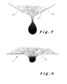
- the water that trickles downwards through the substrate arrives, because of the water-absorbing character of the substrate, at the parts of the substrate sticking out of the drainage hole, where drops are formed that hang only from the protruding part of the substrate. Because of the smaller base of these drops, they fall down more quickly, that means, in the form of smaller drops. Moreover, they do not block the drainage hole completely, so that the air can always enter the drainage hole so as to ventilate the substrate.
- the lower bottom part has, at the location of the drainage holes, a determined width measured from the indentation to the sidewall, and the drainage holes extend up to a determined distance from the sidewall and from the indentation, which distance is smaller than 40% and preferably smaller than 30% from the width of the lower bottom part.
- This preferred embodiment offers the advantage that only a limited part of the valleys in the lower bottom part is not formed by a drainage hole. Only a very small portion of the substrate will thus be located in these wettest parts of the pot, the major part of the substrate draining effectively towards the drainage holes and in a limited measure towards these wettest parts. Since the wettest parts of the pot are placed effectively adjacent to the drainage holes, they will actually dry up relatively quickly after the water supply towards these lowest parts is ended.
- the drainage holes of the pot are located, when the pot is placed on a flat support, at a distance from their undersides to the flat support of less than 5 mm, preferably less than 3 mm.
- At least some of the drainage holes provided in said valley join ventilation holes provided in the central indentation, so that two transitions are formed between the rim of the drainage hole and the rim of the ventilation hole connected to it, whereby, close to said transitions, the rims of the drainage holes and the rims of the ventilation holes connected thereto drain towards these transitions.
- An advantage of this embodiment is that, when the substrate is pressed or shaken, the substrate that finds itself at the ventilation opening can slide further down, so that the substrate below in the drainage hole connected thereto will protrude faster from the bottom and thus ensure an efficient drop forming location. In other words, the downwards slide of the substrate is not hindered by any separation between the ventilation hole and the drainage hole located below.
- the pot according to the invention is a pot that is suitable for growing several sorts of plants, in particular for growing plants with a root structure that develops itself relatively badly and/of a root structure that is sensitive to rot.
- the pot is particularly suitable for growing, for example, Saint Paulia, Azalea, pot roses, Kalanchoe and Spatiphyllum.
- the pot can be filled to this purpose with earth or with another substrate such as potting soil containing peat. It is important for the pot that it allows as quick a drainage of the substrate as possible, so that after being watered the roots can be optimally provided with oxygen as quickly as possible. This watering may happen either from above or laterally through a so-called tide-and-ebb system.
- the pots can be made from all sorts of materials and in all sorts of different shapes. In most cases they are manufactured from plastic, for example from polypropylene, and this by an injection moulding process.
- the pots can be, for example, round, square or square-round (square above and round below).
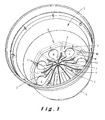
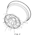
- the pot comprises a bottom 1, a sidewall 2 connected thereto and one or more support feet 3 below the bottom 1. These support feet 3 ensure that the bottom does not rest itself on the support, as a result of which the water can flow freely out of the pot.
- the bottom 1 of the pot is formed by a nearly central indentation 4 with a lower bottom part 5 around it which extends from the central indentation 4 up to the sidewall 2.
- the sidewall 2 will widen upwards to some extent, while the indentation 4 will narrow upwards.
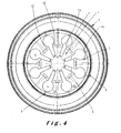
- drainage holes 6 are provided round the central indentation 4, in the lower bottom part 5, which in the shown embodiment, are placed in a circle. These drainage holes 6 occupy at least 5%, preferably at least 10% and most preferably at least 15% of the surface of the lower bottom part 5 around the central indentation. The drainage holes do however not only ensure the drainage of the pot, but also its ventilation. In the shown embodiment, the drainage holes 6 occupy approximately 28% of the surface of the lower bottom part 5.
- the drainage holes 6 can present all sorts of regular or irregular shapes such as round, oval, rectangular square, hexagonal, etc. As indicated in the drawings, they are preferably round.
- the surface of each one of the drainage holes is preferably larger than 30 mm 2 , and more preferably larger than 50 mm 2 . Round holes have preferably a diameter larger than 6 mm, more preferably larger than 8 mm and most preferably larger than 10 mm. In the 12 cm pot shown in the drawings, the round drainage holes have for example a diameter of approximately 13 mm.
- the central indentation 4 is intended to promote the ventilation of the substrate.
- the indentation forms preferably more than 15%, more preferably more that 25%, but preferably less than 45% and more preferably less than 35% of the bottom surface.
- the indentation extends in particular up to a height h of at least 15%, preferably up to a height h of at least 20% and most preferably up to a height h of at least 25% of the total height H of the pot.
- the central indentation 4 is provided in the shown embodiment with ventilation holes 7. These ventilation holes 7 can be completely separate from the drainage holes 6, but in the shown embodiment the ventilation holes are elongated so that each ventilation hole 7 connects with a drainage hole 6. As it will be further described in detail, this connection is shaped so as to promote the drainage from the pot.
- peaks 8, valleys 9 and flanks 10 Preferably at least three, more preferably at least four and most preferably at least five valleys 10 are formed.
- the drainage holes 6 are provided in these valleys, preferably one in each valley, and extend over the two adjacent flanks 10. In this manner, the rims of the drainage holes 6 drain towards at least two lowest points 11. In the shown embodiment there are three points 11 towards which the rims of the drainage holes 6 drain, since these rims are interrupted by the ventilation holes 7.
- the flanks 10 have preferably a slope percentage measured in the tangential direction between the drainage holes 6 and the adjacent peak 8 that, at the level of the drainage holes is overall higher than 10%, more preferably higher than 15% and most preferably higher than 20% (the slope percentage is the "average" percentage determined by taking the tangent of the angle formed between the horizontal plane and a line linking the valley and the adjacent peak). Moreover, the slope percentage of the flanks is preferably overall at the level of the drainage holes preferably lower than 400%, more preferably lower than 175% and most preferably lower than 100%.
- the slope percentage at the outer end of the drainage holes 6 is approximately 23% and at the inner end of these holes approximately 35% (due to the fact that at the outer side the distances between the valleys 9 and the peaks 8 are bigger, so that the flanks have a sort of helical shape).
- the slope percentage at the outer end of the drainage holes could be increased by inclining the peaks 8 upwards towards the sidewall 2.
- the surface of the lower bottom part 5 at the outer side of the drainage holes 6, in other words, along the sidewall 2, is inclined upwards towards this sidewall, so that, when the drainage holes 6 are not provided up to the sidewall, the water will flow from this sidewall 2 towards the holes 6.
- the surface of the lower bottom part 5 is also inclined upwards along the central indentation 4 from the lower bottom part 5 towards this central indentation 4.
- the bottom part 5 is inclined upwards, both along the sidewall 2 as along the indentation 4, with a slope that is smaller than the maximal slope of, respectively, the sidewall 2 (about 82° in the drawings) and the indentation 4 (about 55° in the drawings). The transition between the lower bottom part 5 and the sidewall 2 or the central indentation 4 happens thus at the place where the maximal slope angle is reached.
- the drainage holes 6 stretch preferably sufficiently far towards the sidewall 2 and towards the central indentation 4. If the lower bottom part 5 has a width B, measured between the indentation 4 and the sidewall 2, the drainage holes then preferably extend to a distance from the sidewall 2 and from the central indentation 4 which is less than 40% of the width B, and which is more preferably less than 30% of this width.
- the drainage holes 6 are circular and approximately extend up to the transition between the lower bottom part 5 and the central indentation 4, more precisely up to the part of the bottom inclined upwards towards the central indentation.
- the transitions between the rims of the drainage holes 6 and those of the ventilation holes 7 connected thereto are also each located near the transition between the lower bottom part 5 and the central indentation 4, more precisely also in the part of the bottom which is inclined upwards. Near these transitions, the rims of the drainage holes 6 as well as the rims of the ventilation holes 7 connected thereto drain towards these transitions.
- the ventilation holes 7 in the shown pot are narrower than the drainage holes 6 to which they are connected.
- a sort of gutters 12 are formed at the position of the transitions between the rims of both holes 6 and 7. Once the biggest part of the water has leaked out of the substrate, an accumulation of water will still remain at the position of these gutters 12, which can still trickle out of the substrate through these gutters 12.
- the plane of the lower bottom part 5 at the position of the gutters 12 is preferably bent downwards to further promote the drainage of the remaining water. Due to this, the substrate can also sag further, so that a protruding substrate part is formed in which efficient (smaller) drops form. This is however not shown in the drawings.
- the drainage of the substrate is also promoted by that, when the pot is placed on a flat support, the drainage holes of the pot are located at a distance from their undersides to the flat support of less than 5 mm, preferably less than 3 mm.
- the substrate protruding downwards through the drainage holes 6 thus finds itself even closer to the flat support, so that, when drops form at this substrate, the drops quickly come in contact with the support and thus flow out. Therefore, even more water is extracted from the pot by the cohesive forces in the water.
- the pot shown in the drawings is optimal for draining the substrate.
- the water flows always from any position in the bottom towards the drainage holes 6. Because of the three-dimensional form of these holes 6, the lowest part will mostly be formed by the downward protruding substrate.
- drop formation will quickly take place in this protruding part of the substrate and, more particularly, small drops will be formed that drop off quickly and that do not completely close the drainage holes to air.
- good drainage will be combined with good ventilation, even more so due to the presence of the ventilation holes that extend up to the drier part of the substrate.
Landscapes
- Life Sciences & Earth Sciences (AREA)
- Environmental Sciences (AREA)
- Cultivation Receptacles Or Flower-Pots, Or Pots For Seedlings (AREA)
Applications Claiming Priority (1)
| Application Number | Priority Date | Filing Date | Title |
|---|---|---|---|
| NL1032398A NL1032398C2 (nl) | 2006-08-31 | 2006-08-31 | Pot voor het kweken van een plant. |
Publications (1)
| Publication Number | Publication Date |
|---|---|
| EP1894466A2 true EP1894466A2 (de) | 2008-03-05 |
Family
ID=38177049
Family Applications (1)
| Application Number | Title | Priority Date | Filing Date |
|---|---|---|---|
| EP20070115445 Withdrawn EP1894466A2 (de) | 2006-08-31 | 2007-08-31 | Topf zum Züchten einer Pflanze |
Country Status (2)
| Country | Link |
|---|---|
| EP (1) | EP1894466A2 (de) |
| NL (1) | NL1032398C2 (de) |
Cited By (4)
| Publication number | Priority date | Publication date | Assignee | Title |
|---|---|---|---|---|
| NL2008780C2 (nl) * | 2012-05-09 | 2013-11-12 | Voskamp Vollebregt Holding B V | Plantpot met verhoogde bodem. |
| US20160212944A1 (en) * | 2015-01-26 | 2016-07-28 | Plantlogic LLC | Stackable pots for plants |
| WO2018096283A1 (fr) * | 2016-11-25 | 2018-05-31 | Veritable | Dispositif de culture végétale |
| EP4559308A1 (de) * | 2023-11-27 | 2025-05-28 | Pöppelmann Holding GmbH & Co. KG | Pflanztopf mit stapelrand |
Citations (5)
| Publication number | Priority date | Publication date | Assignee | Title |
|---|---|---|---|---|
| US4173097A (en) | 1977-09-14 | 1979-11-06 | Staby George L | Container with raised indentations for aeration and drainage |
| DE9308335U1 (de) | 1993-06-03 | 1993-07-22 | Gebr. Pöppelmann, Kunststoffwerk-Werkzeugbau, 49393 Lohne | Pflanztopf |
| NL1006709C1 (nl) | 1997-08-01 | 1999-02-02 | Handelsonderneming Van Krimpen | Druppelgeleider. |
| NL1018022C2 (nl) | 2001-05-08 | 2002-11-12 | Interco B V | Plantpot. |
| EP1527676A2 (de) | 2003-10-29 | 2005-05-04 | Novabouw | Topf und Verfahren zum Züchten einer Luftpflanze |
Family Cites Families (3)
| Publication number | Priority date | Publication date | Assignee | Title |
|---|---|---|---|---|
| NL9500175A (nl) * | 1995-02-01 | 1996-09-02 | Synprodo Hortiproducts Bv | Bloempot. |
| DE20119165U1 (de) * | 2001-11-26 | 2003-03-06 | Gebr. Pöppelmann, Kunststoffwerk-Werkzeugbau, 49393 Lohne | Pflanztopf aus Kunststoff |
| NL1027797C2 (nl) * | 2004-12-16 | 2006-06-27 | Handelsonderneming Van Krimpen | Plantpot. |
-
2006
- 2006-08-31 NL NL1032398A patent/NL1032398C2/nl not_active IP Right Cessation
-
2007
- 2007-08-31 EP EP20070115445 patent/EP1894466A2/de not_active Withdrawn
Patent Citations (5)
| Publication number | Priority date | Publication date | Assignee | Title |
|---|---|---|---|---|
| US4173097A (en) | 1977-09-14 | 1979-11-06 | Staby George L | Container with raised indentations for aeration and drainage |
| DE9308335U1 (de) | 1993-06-03 | 1993-07-22 | Gebr. Pöppelmann, Kunststoffwerk-Werkzeugbau, 49393 Lohne | Pflanztopf |
| NL1006709C1 (nl) | 1997-08-01 | 1999-02-02 | Handelsonderneming Van Krimpen | Druppelgeleider. |
| NL1018022C2 (nl) | 2001-05-08 | 2002-11-12 | Interco B V | Plantpot. |
| EP1527676A2 (de) | 2003-10-29 | 2005-05-04 | Novabouw | Topf und Verfahren zum Züchten einer Luftpflanze |
Cited By (8)
| Publication number | Priority date | Publication date | Assignee | Title |
|---|---|---|---|---|
| NL2008780C2 (nl) * | 2012-05-09 | 2013-11-12 | Voskamp Vollebregt Holding B V | Plantpot met verhoogde bodem. |
| US20160212944A1 (en) * | 2015-01-26 | 2016-07-28 | Plantlogic LLC | Stackable pots for plants |
| US10076085B2 (en) * | 2015-01-26 | 2018-09-18 | Plantlogic LLC | Stackable pots for plants |
| US10342183B2 (en) * | 2015-01-26 | 2019-07-09 | Plantlogic LLC | Stackable pots for plants |
| WO2018096283A1 (fr) * | 2016-11-25 | 2018-05-31 | Veritable | Dispositif de culture végétale |
| FR3059205A1 (fr) * | 2016-11-25 | 2018-06-01 | Veritable | Dispositif de culture vegetale |
| CN110022673A (zh) * | 2016-11-25 | 2019-07-16 | 维瑞拓博公司 | 植物栽培装置 |
| EP4559308A1 (de) * | 2023-11-27 | 2025-05-28 | Pöppelmann Holding GmbH & Co. KG | Pflanztopf mit stapelrand |
Also Published As
| Publication number | Publication date |
|---|---|
| NL1032398C2 (nl) | 2008-03-03 |
Similar Documents
| Publication | Publication Date | Title |
|---|---|---|
| US6266921B1 (en) | Cell and cell tray for growing seedlings | |
| US7093391B2 (en) | Plant pot drainage tray | |
| US7774981B2 (en) | Plant container and method | |
| JP2004513665A (ja) | 植物の栽培状態を改善するための成形体 | |
| US6601342B2 (en) | Culture tray for the rooting of young plants | |
| EP1894466A2 (de) | Topf zum Züchten einer Pflanze | |
| US20140090294A1 (en) | Planter, Planting and Method of Growing Plants | |
| CN109475093B (zh) | 改进花盆 | |
| DK2818038T3 (en) | PLANT POT | |
| CA2897183C (en) | Moisture control grid | |
| EP0181328B1 (de) | Blumentopf | |
| KR20150109210A (ko) | 텃밭용 화분 | |
| JP4431774B2 (ja) | 流水育苗ポット台 | |
| EP1741332B1 (de) | Schale mit Griff | |
| EP3238530A2 (de) | Bewässerungsvorrichtung | |
| KR200278197Y1 (ko) | 식물재배용 화분용기 | |
| FI110156B (fi) | Kelluva kasvien kasvatuslaite | |
| NL1027797C2 (nl) | Plantpot. | |
| KR200369931Y1 (ko) | 화분파렛트 | |
| KR200493718Y1 (ko) | 식물 재배용 파이프형 화분 | |
| EP0883335B1 (de) | Zuchtverfahren für blumen- end blätterpflanzen und tubulares element dafür | |
| KR20060022175A (ko) | 화분파렛트 | |
| JP3124437U (ja) | 合成樹脂育苗箱 | |
| JP3034456U (ja) | 育苗用シート | |
| CA2956044C (en) | An irrigation device |
Legal Events
| Date | Code | Title | Description |
|---|---|---|---|
| PUAI | Public reference made under article 153(3) epc to a published international application that has entered the european phase |
Free format text: ORIGINAL CODE: 0009012 |
|
| AK | Designated contracting states |
Kind code of ref document: A2 Designated state(s): AT BE BG CH CY CZ DE DK EE ES FI FR GB GR HU IE IS IT LI LT LU LV MC MT NL PL PT RO SE SI SK TR |
|
| AX | Request for extension of the european patent |
Extension state: AL BA HR MK YU |
|
| STAA | Information on the status of an ep patent application or granted ep patent |
Free format text: STATUS: THE APPLICATION IS DEEMED TO BE WITHDRAWN |
|
| 18D | Application deemed to be withdrawn |
Effective date: 20130301 |