EP1894632A2 - Plaque de distribution et plaque de diffusion montées sur un arbre - Google Patents
Plaque de distribution et plaque de diffusion montées sur un arbre Download PDFInfo
- Publication number
- EP1894632A2 EP1894632A2 EP07253219A EP07253219A EP1894632A2 EP 1894632 A2 EP1894632 A2 EP 1894632A2 EP 07253219 A EP07253219 A EP 07253219A EP 07253219 A EP07253219 A EP 07253219A EP 1894632 A2 EP1894632 A2 EP 1894632A2
- Authority
- EP
- European Patent Office
- Prior art keywords
- shaft
- sleeve
- plate
- diffuser
- distribution plate
- Prior art date
- Legal status (The legal status is an assumption and is not a legal conclusion. Google has not performed a legal analysis and makes no representation as to the accuracy of the status listed.)
- Withdrawn
Links
Images




Classifications
-
- B—PERFORMING OPERATIONS; TRANSPORTING
- B05—SPRAYING OR ATOMISING IN GENERAL; APPLYING FLUENT MATERIALS TO SURFACES, IN GENERAL
- B05B—SPRAYING APPARATUS; ATOMISING APPARATUS; NOZZLES
- B05B3/00—Spraying or sprinkling apparatus with moving outlet elements or moving deflecting elements
- B05B3/02—Spraying or sprinkling apparatus with moving outlet elements or moving deflecting elements with rotating elements
- B05B3/04—Spraying or sprinkling apparatus with moving outlet elements or moving deflecting elements with rotating elements driven by the liquid or other fluent material discharged, e.g. the liquid actuating a motor before passing to the outlet
- B05B3/0417—Spraying or sprinkling apparatus with moving outlet elements or moving deflecting elements with rotating elements driven by the liquid or other fluent material discharged, e.g. the liquid actuating a motor before passing to the outlet comprising a liquid driven rotor, e.g. a turbine
- B05B3/0425—Spraying or sprinkling apparatus with moving outlet elements or moving deflecting elements with rotating elements driven by the liquid or other fluent material discharged, e.g. the liquid actuating a motor before passing to the outlet comprising a liquid driven rotor, e.g. a turbine actuated downstream of the outlet elements
- B05B3/0426—Spraying or sprinkling apparatus with moving outlet elements or moving deflecting elements with rotating elements driven by the liquid or other fluent material discharged, e.g. the liquid actuating a motor before passing to the outlet comprising a liquid driven rotor, e.g. a turbine actuated downstream of the outlet elements the liquid driven rotor being a deflecting rotating element
-
- B—PERFORMING OPERATIONS; TRANSPORTING
- B05—SPRAYING OR ATOMISING IN GENERAL; APPLYING FLUENT MATERIALS TO SURFACES, IN GENERAL
- B05B—SPRAYING APPARATUS; ATOMISING APPARATUS; NOZZLES
- B05B3/00—Spraying or sprinkling apparatus with moving outlet elements or moving deflecting elements
- B05B3/003—Spraying or sprinkling apparatus with moving outlet elements or moving deflecting elements with braking means, e.g. friction rings designed to provide a substantially constant revolution speed
- B05B3/005—Spraying or sprinkling apparatus with moving outlet elements or moving deflecting elements with braking means, e.g. friction rings designed to provide a substantially constant revolution speed using viscous dissipation, e.g. a rotor movable in a chamber filled with oil
Definitions
- This invention relates to rotary sprinklers and, more specifically, to a rotary sprinkler having a stream diffuser driven in random fashion by a stream emitted from a fixed nozzle and redirected by a grooved water distribution plate in the form of plural secondary streams, some of which strike the diffuser.
- a water distribution plate and an axially spaced stream diffuser plate are mounted for rotation on a solid shaft and a hollow sleeve, respectively, surrounding the shaft. Rotation of the water distribution plate causes rotation of the diffuser plate by reason of a viscous fluid coupling between the shaft and the sleeve. Viscous damping also slows the respective rates of rotation of the two plates.
- the shaft is fixed and extends upwardly through the nozzle of a sprinkler head or body.
- the shaft supports the water distribution plate and diffuser plate downstream of an arcuate or full circle stream emitted from the nozzle.
- the water distribution plate has a generally truncated cone shape, and is formed with a plurality of grooves that are slightly curved in a circumferential direction so that when the stream emitted from the nozzle impinges on the grooves, the water distribution plate is caused to rotate about the shaft.
- a first stator component is fixed to the shaft and located within a sealed first chamber in the water distribution plate.
- the chamber is at least partially filled with a viscous fluid that causes the rate of rotation of the water distribution plate to be significantly slowed in comparison to an unbraked rate of rotation.
- the diffuser plate Downstream of the water distribution plate, the diffuser plate is mounted on a sleeve surrounding a portion of the shaft.
- a second stator component is fixed to the sleeve in a second sealed chamber in the water distribution plate that is also at least partially filled with viscous fluid.
- the diffuser plate is provided with a plurality of diffuser elements projecting downwardly from a peripheral edge of the lower surface of the diffuser.
- the lower end of the sleeve terminates adjacent the first stator and the upper end of the sleeve terminates within the body of the diffuser plate, with viscous fluid in the annular space between the sleeve and the shaft.
- the shaft is supported by bearings on either side of both stators, and by a bearing in the diffuser body, above the sleeve.
- the shaft extends from the sprinkler body, through both the distributor plate and the diffuser plate, while the sleeve, which is of shorter axial length, extends only between the distributor plate and the diffuser plate. Seals and retainer rings are used to keep the bearings in place and to prevent leakage of viscous fluid along the shaft.
- the stream emitted from the nozzle impinges on the water distribution or first plate provided with the drive grooves, causing it to rotate about the shaft.
- the rotation of the first plate is dampened or slowed by the first viscous brake mechanism within the distributor plate and by the viscous coupling between the shaft and the sleeve.
- individual random ones of the secondary streams impinge on the diffuser elements on the diffuser plate.
- the diffuser plate does not need to be positively driven, however, because of the shearing action of the silicone fluid between the hollow shaft and the solid shaft. In other words, a rotating action of either plate will cause the other plate to rotate because of this viscous fluid coupling.
- surfaces on the diffuser elements may be shaped as vane surfaces to drive the plate when impinged upon by the secondary streams from the water distribution plate.
- the water distribution plate and diffuser plate are again mounted on a single shaft, but the shaft is supported for rotation within a sprinkler cap assembly or housing that is in turn supported on the sprinkler body downstream of the nozzle.
- the shaft does not project upwardly through the sprinkler nozzle.
- the water distribution plate is fixed at one end of the shaft, for rotation with the shaft when a stream emitted from the nozzle impinges on drive grooves formed in the plate.
- the opposite end of the shaft is seated in a blind bore formed in a remote end of a housing component downstream of the nozzle.
- a first rotor is fixed to the shaft at the remote end of the housing, with a first housing bearing sealing a first chamber in which the first rotor is received.
- the chamber is at least partially filled with a viscous fluid and rotation of the distributor plate is dampened or slowed by viscous shearing of the fluid between the rotor and the chamber wall.
- the diffuser plate is supported by a sleeve, adjacent the water distribution plate, and telescoped over the shaft.
- the shaft passes through a bearing supported in the diffuser plate, and the sleeve is supported by first and second housing bearings.
- a second rotor is fixed to the sleeve and the first and second housing bearings form the ends of a second chamber for the second rotor.
- the second chamber is also at least partially filled with viscous fluid.
- the diffuser plate in this embodiment is formed with curved grooves with raised flats between the grooves. In use, this second embodiment operates in a manner generally similar to the first-described embodiment.
- the invention relates to a water distribution and diffuser assembly for a sprinkler comprising: a shaft; a distribution plate mounted on the shaft for rotation relative to the shaft; and wherein the shaft passes through and extends beyond the distribution plate; a sleeve telescoped over at least a portion of the shaft; a diffuser plate fixed to the sleeve downstream of the distribution plate; and wherein the shaft passes through the sleeve, with the shaft supporting bearings in the distribution plate and on the diffuser plate.
- the invention in another aspect, relates to a sprinkler comprising a sprinkler body incorporating a nozzle, a fixed shaft extending downstream of the nozzle and supporting a water distribution plate for rotation relative to the shaft, the water distribution plate formed with drive grooves adapted to receive a stream from the nozzle and to create secondary streams within the drive grooves causing rotation of the water distribution plate; a sleeve received over the shaft for rotation relative to the shaft and relative to the water distribution plate, the sleeve mounting a diffuser plate for rotation with the sleeve, the diffuser plate having diffuser elements adapted to be struck by at least some of the secondary streams; and wherein viscous fluid is present in an annular space between the shaft and the sleeve.
- the invention in still another aspect, relates to a sprinkler comprising a nozzle adapted to emit a stream to atmosphere, a water distribution plate and diffuser plate assembly located downstream of the nozzle, the assembly comprising a shaft mounted in a housing for rotation relative to the housing; a water distribution plate fixed to one end of the shaft, the water distribution plate formed with at least one drive groove adapted to receive the stream; a sleeve received over a portion of the shaft, the sleeve mounting a diffuser plate adjacent the water distribution plate, at one end of the sleeve; the shaft and the sleeve supported by plural bearings enabling the sleeve and the diffuser plate to rotate relative to the water distribution plate and the shaft; and wherein at least one of the shaft and the sleeve mount a rotor located in a chamber at least partially filled with viscous fluid.
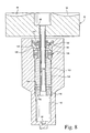
- a sprinkler head is partially shown at 10 and incorporates a schematically depicted nozzle 12 supporting one end of a shaft 14.
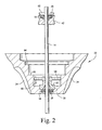
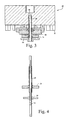
- the shaft 14 (see also Figs. 2 and 3) extends out of the sprinkler head, in a downstream direction, and supports a water distribution plate and diffuser plate assembly 16 for impingement by a stream S emitted from the nozzle.
- a stream deflector 18 is fixed to the shaft 14 and cooperates to define the nozzle orifice 20.
- the deflector guides an arcuate (or round) stream onto the water distribution plate 22 formed with a plurality of grooves 24 shaped to divide the single vertically-oriented arcuate or full 360° stream emitted from the nozzle 12 into a plurality of secondary streams or stream components, and to redirect those stream components in a generally radial direction.
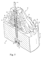
- Grooves 24 are also curved slightly in a circumferential direction (see Figure 5) such that the water distribution plate 22 is caused to rotate about the shaft 14 as a result of the plurality of stream components acting on the interior walls of the grooves.
- Such water distribution plates are well-known in the art.
- a diffuser plate component 26 of the assembly 16 is supported on a sleeve 28 that is telescoped over the shaft 14. As explained in further detail below, the diffuser plate 26 and sleeve 28 are able to rotate relative to the fixed shaft 14 and independently of the water distribution plate 22.
- the diffuser plate 26 is provided with a plurality of diffuser elements 30, projecting below a lower surface 32 of the plate 26, and arranged about a peripheral edge thereof. Each diffuser element may be provided with a curved vane surface 34 (see especially Figure 5) such that when secondary streams from the distribution plate impinge on the diffusion plate, the latter is caused to rotate.
- rotation of the water distribution plate 22 is substantially uniform while rotation of the diffuser plate 26 is intermittent and random.
- the water distribution plate 22 is bored and counterbored to essentially hollow out the plate, with a series of annular shoulders at increasing radii in a downstream direction from a center axis defined by the shaft 14. More specifically, a first shoulder 35 axially adjacent the nozzle 12 supports a first conventional double-lip seal 36 that engages the shaft 14. A second shoulder 38 supports a first distributor plate bearing 40 that supports the shaft at a location proximate the nozzle 12. The opposite end of the shaft is supported by a second distributor plate bearing 42 that is, in turn, press-fit into a counterbore 44 (Figure 1) in the plate 26 and supported on a shoulder 46 formed in the plate. A flexible double-lip seal 48 is supported on a shoulder 50 formed in the bearing 42, and a retainer 52 holds the seal in place.
- a fixed (or first) stator 54 is fixed to the shaft 14 at a location adjacent the bearing 40 and forms part of a first viscous brake mechanism designed to slow rotation of the distribution plate as explained further below.
- the diffuser plate 26 is press-fit on the sleeve 28, the latter extending into a counterbore 56 in the diffuser plate, and terminating at a location below the bearing 42 ( Figure 2).
- the sleeve 28 is telescoped over the shaft 14 (see also Figures 1 and 4), and the opposite end of the sleeve 28 is seated in a diffuser plate bearing 58 supported on a shoulder 60 ( Figures 1 and 2) in the distribution plate 22.
- the sleeve 28 is also supported by a second diffuser plate bearing 62 ( Figures 1 and 3) seated on a shoulder 64 in the distribution plate 22.
- Bearing 62 supports a flexible double-lip seal 66 on a bearing shoulder 68, and a retainer disc 70 is press-fit over the shaft and into the distribution plate 22 until it engages shoulder 72.
- a second stator disk or stator 74 is fixed to the sleeve 28 between bearings 58 and 62.
- bearings 40 and 58 have respective sleeve portions 76, 78 that abut the stator 54.
- a second sleeve portion 80 on the opposite side of bearing 58 and a lower end of the bearing 62 engage opposite sides of the second stator 74.
- the water distribution plate stator (or first stator) 54 is located in a chamber 82 with ends of the chamber closed by bearings 40 and 58.
- Chamber 82 is at least partially filled with a silicone or other suitable viscous fluid. It will be understood that the speed of rotation of the distribution plate 22 will be slowed by the fluid shearing action in chamber 82 resulting from the rotation of the plate 22 relative to the fixed stator 54.
- a second chamber 84 is closed at opposite ends by bearings 58 and 62.
- the diffuser plate (or second) stator 74 is located in the chamber 84, and the latter is also at least partially filled with a viscous fluid. In this way, rotation of the diffuser plate 26 which is fixed to the sleeve 28 is slowed by the viscous shearing in the chamber 84.
- a stream of water emitted from the nozzle orifice 20 will engage the grooves 24, and break up into plural secondary streams.
- the curved grooves will cause the plate 22 to rotate but the speed of rotation will be slowed by reason of viscous shearing of fluid between the shaft 14 and sleeve 28, as explained above.
- the diffuser element vane surfaces 34 of the diffuser elements 30 may or may not be curved so as to cause rotation of the diffuser plate 26 when struck by secondary streams.
- viscous fluid present between the shaft 14 and the sleeve 28 establishing a fluid coupling therebetween, such that rotation of the distribution plate 22 will cause some degree of rotation of the diffuser plate 26. Nevertheless, rotation of the plate 26 may be enhanced by curving the vane surfaces 34.
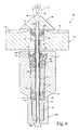
- FIG. 6-10 A second embodiment of a combined water distribution plate/diffuser assembly 86 is shown in Figures 6-10.
- a more sharply defined conically-shaped water distribution plate 88 formed with curved grooves 89 is fixed to one end of a shaft 90.
- a diffuser plate 92 provided with diffuser elements or grooves 94 is supported on the shaft via bearing 96 adjacent the water distribution plate, and the opposite end of the shaft 90 is received in a blind recess 98 at a remote end of a fixed housing 100, but so as to be able to rotate relative to the housing.
- Bearing 96 is seated on a shoulder 97 defined by a counterbore 100 in the plate 92.
- Bearing 96 supports a flexible double-lip seal 102 and both the bearing and lip seal are held in place by a retainer 104.
- a nozzle (not shown) emits a single solid stream S that is located upstream of the water distribution plate 88, and the shaft 90 forms no part of, nor does it extend through, the nozzle supported in the sprinkler body as in the previously described embodiment. It will be appreciated, of course, that the configuration as shown in Figure 6 (including the nozzle) may be inverted.
- the grooves 89 (best seen in Figure 10) in the water distribution plate 88 cause the plate 88 to rotate with the shaft, but here, the grooves continue to an apex 106 on which the solid stream S impinges and breaks up into secondary streams or stream components that flow through the grooves 94, causing rotation of the plate 92 and shaft 90.
- the opposite end of shaft 90 is received in the blind recess 98, with a thrust bearing 108 interposed between the shaft end and the end face of the recess.
- the blind recess or bore 98 is counterbored to partially define a cavity 110 that receives a first substantially cylindrical rotor 112 fixed to the shaft 90.
- a sleeve 114 receives the diffuser plate 92 in a press-fit relationship, the sleeve telescoped over the shaft 90 and extending from the diffuser plate 92 adjacent bearing 96, into the housing 100 where it terminates within a bearing 116 located adjacent the rotor 112.
- the bearing 116 is seated on a shoulder 118 formed by a counterbore 120.
- a second substantially cylindrical rotor 122 is fixed to the sleeve 114 and is located in a second chamber 124 substantially closed by the bearing 116 and a ball bearing 126 that also supports the sleeve 114 within the housing 100.
- a retainer 128 for the ball bearing 126, a seal support ring 130 and a flexible double-lip seal 132 are all mounted on the sleeve 114, with supporting ring 130 seated on shoulder 134 and lip seal 132 seated on ring shoulder 136.
- a retainer 137 holds the lip seal 132 in place.
- the second chamber 124 is also at least partially filled with viscous fluid so that the rotation speed of the diffuser plate 92 is slowed by the interaction of rotor 122 and the viscous fluid in the second chamber 124.
- viscous fluid is present in the radial space 138 between the shaft 90 and sleeve 114.
- the fluid is available from the first chamber 110 that is in fluid communication with space 118 via bore 140 in the bearing 116.
- the assembly 86 operates in much the same manner as the first-described embodiment. Specifically, water impinging on the plate 88 will cause that plate to rotate but at a reduced speed due to the viscous dampening or braking that results from the rotation of shaft 90 and rotor 112 in the first viscous chamber 110.
- the diffuser plate 92 will rotate at a different speed when struck by secondary streams from the grooves 89 by reason of the curvature of grooves 94 but also by reason of the fluid coupling established between the shaft 90 and sleeve 114 via the viscous fluid in space 138.
- grooves 94 may or may not be curved, i.e., they may or may not serve as drive grooves. It will be understood that some of the secondary streams will also impinge on, and be diffused by, raised flats 142 circumferentially between the grooves 94 since the plate 88 rotates faster than the diffuser plate 92.
Landscapes
- Nozzles (AREA)
Applications Claiming Priority (1)
| Application Number | Priority Date | Filing Date | Title |
|---|---|---|---|
| US11/513,011 US7624935B2 (en) | 2006-08-31 | 2006-08-31 | Distributor plate and diffuser plate on sleeved shaft |
Publications (2)
| Publication Number | Publication Date |
|---|---|
| EP1894632A2 true EP1894632A2 (fr) | 2008-03-05 |
| EP1894632A3 EP1894632A3 (fr) | 2008-08-27 |
Family
ID=38543596
Family Applications (1)
| Application Number | Title | Priority Date | Filing Date |
|---|---|---|---|
| EP07253219A Withdrawn EP1894632A3 (fr) | 2006-08-31 | 2007-08-16 | Plaque de distribution et plaque de diffusion montées sur un arbre |
Country Status (3)
| Country | Link |
|---|---|
| US (1) | US7624935B2 (fr) |
| EP (1) | EP1894632A3 (fr) |
| AU (1) | AU2007209840B2 (fr) |
Cited By (3)
| Publication number | Priority date | Publication date | Assignee | Title |
|---|---|---|---|---|
| CN102423732A (zh) * | 2011-09-30 | 2012-04-25 | 宁波大叶园林工业有限公司 | 一种带水平泡可调垂直度及可调旋转快慢的喷灌器 |
| ITMO20110068A1 (it) * | 2011-03-30 | 2012-10-01 | Gf Srl | Irrigatore per giardini. |
| WO2017021561A1 (fr) * | 2015-07-31 | 2017-02-09 | Vyr-Valvuleria Y Riegos Por Aspersion, S.A. | Asperseur rotatif à vitesse de rotation réglable |
Families Citing this family (16)
| Publication number | Priority date | Publication date | Assignee | Title |
|---|---|---|---|---|
| DE102009017293A1 (de) | 2009-04-11 | 2010-10-14 | Gardena Manufacturing Gmbh | Regner |
| US8567699B2 (en) * | 2009-08-05 | 2013-10-29 | Nelson Irrigation Corporation | Rotary strut sprinkler |
| US8336788B2 (en) * | 2009-08-07 | 2012-12-25 | Nelson Irrigation Corporation | Dripless rotary sprinkler and related method |
| US9321067B2 (en) * | 2010-07-08 | 2016-04-26 | Federal Signal Corporation | Seal cartridge for a rotating nozzle assembly |
| US8833672B2 (en) | 2010-08-20 | 2014-09-16 | Rain Bird Corporation | Flow control device and method for irrigation sprinklers |
| CN102423730A (zh) * | 2011-09-21 | 2012-04-25 | 中国农业科学院农田灌溉研究所 | 一种折射式微喷头 |
| US10350619B2 (en) | 2013-02-08 | 2019-07-16 | Rain Bird Corporation | Rotary sprinkler |
| US9492832B2 (en) | 2013-03-14 | 2016-11-15 | Rain Bird Corporation | Sprinkler with brake assembly |
| US9700904B2 (en) | 2014-02-07 | 2017-07-11 | Rain Bird Corporation | Sprinkler |
| RU2548886C1 (ru) * | 2014-02-25 | 2015-04-20 | Государственное научное учреждение Всероссийский научно-исследовательский институт гидротехники и мелиорации им. А.Н. Костякова Российской академии сельскохозяйственных наук (ГНУ ВНИИГиМ Россельхозакадемии) | Устройство для создания газокапельной струи |
| US10322423B2 (en) | 2016-11-22 | 2019-06-18 | Rain Bird Corporation | Rotary nozzle |
| US11154877B2 (en) | 2017-03-29 | 2021-10-26 | Rain Bird Corporation | Rotary strip nozzles |
| US11511289B2 (en) | 2017-07-13 | 2022-11-29 | Rain Bird Corporation | Rotary full circle nozzles and deflectors |
| US11000866B2 (en) * | 2019-01-09 | 2021-05-11 | Rain Bird Corporation | Rotary nozzles and deflectors |
| US11059056B2 (en) | 2019-02-28 | 2021-07-13 | Rain Bird Corporation | Rotary strip nozzles and deflectors |
| US11406999B2 (en) | 2019-05-10 | 2022-08-09 | Rain Bird Corporation | Irrigation nozzle with one or more grit vents |
Citations (7)
| Publication number | Priority date | Publication date | Assignee | Title |
|---|---|---|---|---|
| US3727842A (en) | 1971-06-24 | 1973-04-17 | Toro Mfg Corp | Agricultural sprinkler head |
| US4375513A (en) | 1980-12-18 | 1983-03-01 | Eli Lilly And Company | Biologically pure culture of Actinoplanes missouriensis |
| US4836449A (en) | 1987-05-15 | 1989-06-06 | Hunter Edwin J | Sprinkler unit with stream deflector |
| US4836450A (en) | 1988-04-29 | 1989-06-06 | Hunter Edwin J | Sprinkler unit with alternating stream interruptor |
| US5192024A (en) | 1990-09-17 | 1993-03-09 | Blee Leonard J | Sprinkler |
| US5372307A (en) | 1993-08-10 | 1994-12-13 | Nelson Irrigation Corporation | Rotary sprinkler stream interrupter |
| US5671886A (en) | 1995-08-23 | 1997-09-30 | Nelson Irrigation Corporation | Rotary sprinkler stream interrupter with enhanced emitting stream |
Family Cites Families (16)
| Publication number | Priority date | Publication date | Assignee | Title |
|---|---|---|---|---|
| US458607A (en) * | 1891-09-01 | Device for cooling liquids | ||
| US3602431A (en) * | 1969-05-23 | 1971-08-31 | Lockwood George | A sprinkler device for fluid distribution |
| IL77747A (en) * | 1986-01-31 | 1991-07-18 | Plastro Gvat | Water sprinkler |
| US5007586A (en) * | 1987-05-13 | 1991-04-16 | Agroteam Consultants Ltd | Rotary sprinklers |
| IL84068A (en) * | 1987-10-01 | 1992-08-18 | Rosenberg Peretz | Rotary sprinklers |
| US4796811A (en) * | 1988-04-12 | 1989-01-10 | Nelson Irrigation Corporation | Sprinkler having a flow rate compensating slow speed rotary distributor |
| IL86226A (en) * | 1988-04-29 | 1992-12-01 | Mamtirim Dan | Rotary sprinkler |
| US5152458A (en) * | 1991-06-13 | 1992-10-06 | Curtis Harold D | Automatically adjustable fluid distributor |
| US5288022A (en) * | 1991-11-08 | 1994-02-22 | Nelson Irrigation Corporation | Part circle rotator with improved nozzle assembly |
| DE4429952A1 (de) * | 1994-08-24 | 1996-02-29 | Gardena Kress & Kastner Gmbh | Regner zum Austrag eines Fluids |
| US7032836B2 (en) * | 2001-03-28 | 2006-04-25 | Nelson Irrigation Corporation | Adjustable arc, adjustable flow rate sprinkler |
| US6494384B1 (en) * | 2001-04-06 | 2002-12-17 | Nelson Irrigation Corporation | Reversible and adjustable part circle sprinkler |
| US6899287B2 (en) * | 2002-12-16 | 2005-05-31 | Senninger Irrigation Inc. | Rotary sprinkler |
| US20040195359A1 (en) * | 2003-03-13 | 2004-10-07 | Curtis Harold D. | Fluid distributing apparatus |
| US7025287B2 (en) * | 2003-08-14 | 2006-04-11 | Nelson Irrigation Corporation | Shaft seal with grease retainer |
| US7143957B2 (en) * | 2004-07-07 | 2006-12-05 | Nelson Irrigation Corporation | Two-axis full-circle sprinkler with bent, rotating nozzle |
-
2006
- 2006-08-31 US US11/513,011 patent/US7624935B2/en not_active Expired - Fee Related
-
2007
- 2007-08-16 EP EP07253219A patent/EP1894632A3/fr not_active Withdrawn
- 2007-08-20 AU AU2007209840A patent/AU2007209840B2/en not_active Ceased
Patent Citations (7)
| Publication number | Priority date | Publication date | Assignee | Title |
|---|---|---|---|---|
| US3727842A (en) | 1971-06-24 | 1973-04-17 | Toro Mfg Corp | Agricultural sprinkler head |
| US4375513A (en) | 1980-12-18 | 1983-03-01 | Eli Lilly And Company | Biologically pure culture of Actinoplanes missouriensis |
| US4836449A (en) | 1987-05-15 | 1989-06-06 | Hunter Edwin J | Sprinkler unit with stream deflector |
| US4836450A (en) | 1988-04-29 | 1989-06-06 | Hunter Edwin J | Sprinkler unit with alternating stream interruptor |
| US5192024A (en) | 1990-09-17 | 1993-03-09 | Blee Leonard J | Sprinkler |
| US5372307A (en) | 1993-08-10 | 1994-12-13 | Nelson Irrigation Corporation | Rotary sprinkler stream interrupter |
| US5671886A (en) | 1995-08-23 | 1997-09-30 | Nelson Irrigation Corporation | Rotary sprinkler stream interrupter with enhanced emitting stream |
Cited By (4)
| Publication number | Priority date | Publication date | Assignee | Title |
|---|---|---|---|---|
| ITMO20110068A1 (it) * | 2011-03-30 | 2012-10-01 | Gf Srl | Irrigatore per giardini. |
| WO2012131529A1 (fr) * | 2011-03-30 | 2012-10-04 | G.F. S.R.L. | Arroseur pour jardins |
| CN102423732A (zh) * | 2011-09-30 | 2012-04-25 | 宁波大叶园林工业有限公司 | 一种带水平泡可调垂直度及可调旋转快慢的喷灌器 |
| WO2017021561A1 (fr) * | 2015-07-31 | 2017-02-09 | Vyr-Valvuleria Y Riegos Por Aspersion, S.A. | Asperseur rotatif à vitesse de rotation réglable |
Also Published As
| Publication number | Publication date |
|---|---|
| US7624935B2 (en) | 2009-12-01 |
| AU2007209840A1 (en) | 2008-03-20 |
| AU2007209840B2 (en) | 2012-04-05 |
| US20080054093A1 (en) | 2008-03-06 |
| EP1894632A3 (fr) | 2008-08-27 |
Similar Documents
| Publication | Publication Date | Title |
|---|---|---|
| AU2007209840B2 (en) | Distributor plate and diffuser plate on sleeved shaft | |
| EP1894633A2 (fr) | Plaque de distribution et diffuseur montés sur arbre fixe | |
| US7100842B2 (en) | Two-axis full-circle sprinkler | |
| US7143957B2 (en) | Two-axis full-circle sprinkler with bent, rotating nozzle | |
| US7395977B2 (en) | Sprinkler apparatus | |
| US5058806A (en) | Stream propelled rotary pop-up sprinkler with adjustable sprinkling pattern | |
| EP3538284B1 (fr) | Arroseur à buse rotative comprenant un diffuseur orbital | |
| US5671885A (en) | Nutating sprinkler with rotary shaft and seal | |
| US6155494A (en) | Rotary nozzle device for emitting a water jet | |
| US8991724B2 (en) | Wobbling sprinkler with viscous brake | |
| US7240860B2 (en) | Water distribution plate for rotating sprinklers | |
| US5671886A (en) | Rotary sprinkler stream interrupter with enhanced emitting stream | |
| US7287710B1 (en) | Sprinkler with magnetic nutating mechanism and related method | |
| US7063274B2 (en) | Cleaning nozzle | |
| JPS60257865A (ja) | スプレーチツプ | |
| PT1384516E (pt) | Motor de turbina de um atomizador rotativo | |
| US7237726B2 (en) | Paint sprayer gun | |
| CN216826735U (zh) | 一种面盖旋转出水花洒 | |
| US20020066801A1 (en) | Fluid atomising device | |
| KR20170106365A (ko) | 회전식 분무기 터빈 | |
| CN101213027B (zh) | 花洒头 | |
| JP2014077397A (ja) | 蒸気タービン | |
| EP1216757A1 (fr) | Dispositif de pulvérisation de fluide | |
| AU4889200A (en) | Rotary atomisers |
Legal Events
| Date | Code | Title | Description |
|---|---|---|---|
| PUAI | Public reference made under article 153(3) epc to a published international application that has entered the european phase |
Free format text: ORIGINAL CODE: 0009012 |
|
| AK | Designated contracting states |
Kind code of ref document: A2 Designated state(s): AT BE BG CH CY CZ DE DK EE ES FI FR GB GR HU IE IS IT LI LT LU LV MC MT NL PL PT RO SE SI SK TR |
|
| AX | Request for extension of the european patent |
Extension state: AL BA HR MK YU |
|
| PUAL | Search report despatched |
Free format text: ORIGINAL CODE: 0009013 |
|
| AK | Designated contracting states |
Kind code of ref document: A3 Designated state(s): AT BE BG CH CY CZ DE DK EE ES FI FR GB GR HU IE IS IT LI LT LU LV MC MT NL PL PT RO SE SI SK TR |
|
| AX | Request for extension of the european patent |
Extension state: AL BA HR MK RS |
|
| STAA | Information on the status of an ep patent application or granted ep patent |
Free format text: STATUS: THE APPLICATION HAS BEEN WITHDRAWN |
|
| 17P | Request for examination filed |
Effective date: 20090226 |
|
| 18W | Application withdrawn |
Effective date: 20090227 |