EP1894762A2 - Radantriebsmotor und Längslenkeraufhängung - Google Patents
Radantriebsmotor und Längslenkeraufhängung Download PDFInfo
- Publication number
- EP1894762A2 EP1894762A2 EP07253402A EP07253402A EP1894762A2 EP 1894762 A2 EP1894762 A2 EP 1894762A2 EP 07253402 A EP07253402 A EP 07253402A EP 07253402 A EP07253402 A EP 07253402A EP 1894762 A2 EP1894762 A2 EP 1894762A2
- Authority
- EP
- European Patent Office
- Prior art keywords
- wheel
- pivot
- wheel drive
- suspension arm
- motor
- Prior art date
- Legal status (The legal status is an assumption and is not a legal conclusion. Google has not performed a legal analysis and makes no representation as to the accuracy of the status listed.)
- Granted
Links
Images

Classifications
-
- B—PERFORMING OPERATIONS; TRANSPORTING
- B60—VEHICLES IN GENERAL
- B60K—ARRANGEMENT OR MOUNTING OF PROPULSION UNITS OR OF TRANSMISSIONS IN VEHICLES; ARRANGEMENT OR MOUNTING OF PLURAL DIVERSE PRIME-MOVERS IN VEHICLES; AUXILIARY DRIVES FOR VEHICLES; INSTRUMENTATION OR DASHBOARDS FOR VEHICLES; ARRANGEMENTS IN CONNECTION WITH COOLING, AIR INTAKE, GAS EXHAUST OR FUEL SUPPLY OF PROPULSION UNITS IN VEHICLES
- B60K7/00—Disposition of motor in, or adjacent to, traction wheel
- B60K7/0007—Disposition of motor in, or adjacent to, traction wheel the motor being electric
-
- B—PERFORMING OPERATIONS; TRANSPORTING
- B60—VEHICLES IN GENERAL
- B60G—VEHICLE SUSPENSION ARRANGEMENTS
- B60G3/00—Resilient suspensions for a single wheel
- B60G3/02—Resilient suspensions for a single wheel with a single pivoted arm
- B60G3/12—Resilient suspensions for a single wheel with a single pivoted arm the arm being essentially parallel to the longitudinal axis of the vehicle
- B60G3/14—Resilient suspensions for a single wheel with a single pivoted arm the arm being essentially parallel to the longitudinal axis of the vehicle the arm being rigid
- B60G3/145—Resilient suspensions for a single wheel with a single pivoted arm the arm being essentially parallel to the longitudinal axis of the vehicle the arm being rigid the arm forming the axle housing
-
- B—PERFORMING OPERATIONS; TRANSPORTING
- B60—VEHICLES IN GENERAL
- B60G—VEHICLE SUSPENSION ARRANGEMENTS
- B60G2200/00—Indexing codes relating to suspension types
- B60G2200/10—Independent suspensions
- B60G2200/13—Independent suspensions with longitudinal arms only
- B60G2200/132—Independent suspensions with longitudinal arms only with a single trailing arm
-
- B—PERFORMING OPERATIONS; TRANSPORTING
- B60—VEHICLES IN GENERAL
- B60G—VEHICLE SUSPENSION ARRANGEMENTS
- B60G2204/00—Indexing codes related to suspensions per se or to auxiliary parts
- B60G2204/10—Mounting of suspension elements
- B60G2204/30—In-wheel mountings
-
- B—PERFORMING OPERATIONS; TRANSPORTING
- B60—VEHICLES IN GENERAL
- B60K—ARRANGEMENT OR MOUNTING OF PROPULSION UNITS OR OF TRANSMISSIONS IN VEHICLES; ARRANGEMENT OR MOUNTING OF PLURAL DIVERSE PRIME-MOVERS IN VEHICLES; AUXILIARY DRIVES FOR VEHICLES; INSTRUMENTATION OR DASHBOARDS FOR VEHICLES; ARRANGEMENTS IN CONNECTION WITH COOLING, AIR INTAKE, GAS EXHAUST OR FUEL SUPPLY OF PROPULSION UNITS IN VEHICLES
- B60K17/00—Arrangement or mounting of transmissions in vehicles
- B60K17/04—Arrangement or mounting of transmissions in vehicles characterised by arrangement, location or kind of gearing
- B60K17/043—Transmission unit disposed in on near the vehicle wheel, or between the differential gear unit and the wheel
- B60K17/046—Transmission unit disposed in on near the vehicle wheel, or between the differential gear unit and the wheel with planetary gearing having orbital motion
-
- B—PERFORMING OPERATIONS; TRANSPORTING
- B60—VEHICLES IN GENERAL
- B60K—ARRANGEMENT OR MOUNTING OF PROPULSION UNITS OR OF TRANSMISSIONS IN VEHICLES; ARRANGEMENT OR MOUNTING OF PLURAL DIVERSE PRIME-MOVERS IN VEHICLES; AUXILIARY DRIVES FOR VEHICLES; INSTRUMENTATION OR DASHBOARDS FOR VEHICLES; ARRANGEMENTS IN CONNECTION WITH COOLING, AIR INTAKE, GAS EXHAUST OR FUEL SUPPLY OF PROPULSION UNITS IN VEHICLES
- B60K7/00—Disposition of motor in, or adjacent to, traction wheel
- B60K2007/0038—Disposition of motor in, or adjacent to, traction wheel the motor moving together with the wheel axle
-
- B—PERFORMING OPERATIONS; TRANSPORTING
- B60—VEHICLES IN GENERAL
- B60K—ARRANGEMENT OR MOUNTING OF PROPULSION UNITS OR OF TRANSMISSIONS IN VEHICLES; ARRANGEMENT OR MOUNTING OF PLURAL DIVERSE PRIME-MOVERS IN VEHICLES; AUXILIARY DRIVES FOR VEHICLES; INSTRUMENTATION OR DASHBOARDS FOR VEHICLES; ARRANGEMENTS IN CONNECTION WITH COOLING, AIR INTAKE, GAS EXHAUST OR FUEL SUPPLY OF PROPULSION UNITS IN VEHICLES
- B60K7/00—Disposition of motor in, or adjacent to, traction wheel
- B60K2007/0092—Disposition of motor in, or adjacent to, traction wheel the motor axle being coaxial to the wheel axle
Definitions
- the subject invention relates to a wheel drive motor that comprises part of a suspension structure.
- Low floor vehicles such as buses for example, utilize electric wheel drives with trailing arm suspensions.
- Each wheel includes a spindle and a wheel drive shaft that rotates relative to the spindle about a lateral axis of rotation.
- a traditional configuration utilizes an electric motor that has a motor output shaft that extends perpendicular to the lateral axis of rotation.
- a right angle, multiple gear reduction box is used to transmit driving power from the motor output shaft to the wheel drive shaft.
- An oil pump is also typically attached to the gear reduction box to provide sufficient lubrication.
- a traditional suspension configuration utilizes a trailing arm that extends underneath the electric motor along a longitudinally extending length of the electric motor.
- the suspension arm includes a pivot end that is attached to a vehicle structure and an attachment end that is fixed to the gear reduction box.
- the electric motor is mounted to the vehicle structure with brackets.
- a suspension for an electrically driven vehicle wheel includes a spindle extending in a lateral direction, an electric motor that drives a vehicle wheel and is mounted to the spindle, and a suspension arm that extends in a longitudinal direction transverse to the lateral direction.
- the electric motor includes a motor housing and an output shaft that is coupled to a wheel drive shaft.
- the output shaft and wheel drive shaft are co-axial.
- the suspension arm includes a pivot end adapted for attachment to a vehicle structure and an attachment end that is rigidly attached to the motor housing such that the electric motor is a structural part of the suspension.
- the motor housing can accommodate torsional loads resulting from forces exerted by the pivot end of the suspension arm.
- the pivot end of the suspension arm includes first and second pivots that are laterally spaced apart from each other.
- the attachment end includes a portion that extends underneath the electric motor, and which has a first flange mount fixed to an inboard facing side of the motor housing and a second flange mount fixed to an outboard facing side of the motor housing.
- the electric motor includes a planetary gear set that is driven by the output shaft.
- the planetary gear set includes a sun gear that is fixed for rotation with the output shaft, a plurality of planet gears in meshing engagement with the sun gear, and a stationary ring gear in meshing engagement with the plurality of planet gears.
- a planet carrier supports the plurality of planet gears via a corresponding plurality of planet pins. The planet carrier provides driving output to the wheel drive shaft.
- the planetary gear set is associated with an outboard end of the output shaft and a parking brake is associated with an inboard end of the output shaft.
- the parking brake includes a rotating component that is driven by the electric motor. A non-rotating component selectively engages the rotating component to apply a parking brake force.
- a wheel drive and suspension is shown generally at 10 in Figure 1.
- the wheel drive and suspension 10 includes a spindle 12, which comprises a non-rotating component, and a wheel drive shaft 14 that rotates about a wheel axis 16 relative to the spindle 12.
- An electric motor 18 includes an output 20 that drives the wheel drive shaft 14.
- the output 20 is co-axial with the wheel axis 16.
- the electric motor 18 drives a vehicle wheel 22 ( Figure 2). Laterally spaced from vehicle wheel 22 is another vehicle wheel (not shown) that would similarly be driven by another electric motor as part of another wheel drive and suspension 10.
- the electric motor 18 is rigidly mounted to a suspension arm 24.
- the suspension arm 24 is a leading or trailing type suspension arm and extends in a direction that is transverse to the wheel axis 16.
- the wheel axis 16 extends in a lateral direction between laterally spaced wheels.
- the suspension arm 24 extends rearwardly or forwardly from the electric motor 18 in a longitudinal direction.
- the suspension arm 24 includes a first flange mount portion 26 that is rigidly mounted to an inboard facing side 28 of the electric motor 18 and a second flange mount portion 30 that is rigidly mounted to an outboard facing side 32 of the electric motor 18.
- the inboard facing side 28 faces toward a vehicle center and the outboard facing side 32 faces toward the vehicle wheel 22.
- the output 20 from the electric motor 18 drives a rotating parking brake component 34.
- the rotating parking brake component 34 can comprise a disc, a cone, a drum, or any other type of rotating parking brake component.
- a non-rotating brake component 36 is selectively engaged with the rotating parking brake component 34 to apply a parking brake force as needed.
- the electric motor 18 includes a motor housing 40 that is mounted directly on top of the suspension arm 24.
- the suspension arm comprises a box-like structure and includes an arm portion 42 that extends underneath the motor housing 40.
- the first 26 and second 30 flange mount portions extend upwardly from opposing outer edges 44 of the arm portion 42 for rigid attachment to opposing sides of the motor housing 40 as described above.
- the motor housing 40 is cradled within a box-like structure formed by the arm portion 42, and the first 26 and second 30 flange mount portions.
- the motor housing 40 is rigidly mounted to the spindle 12 via mounting flange 46 ( Figure 1). This suspension mounting configuration allows the motor housing 40 to form a structural part of the suspension for accommodating certain types of suspension loads. This will be discussed in greater detail below.
- the suspension arm 24 includes a first end 50 that is attached to a vehicle structure 52 and a second end 54 that is attached to the motor housing 40.
- the first end 50 comprises a pivot attachment and the second end 54 comprises a rigid attachment via the first 26 and second 30 flange mount portions, as described above.
- the arm portion 42 extends away from the motor housing 40 in a longitudinal direction toward the pivot attachment.
- the arm portion 42 is defined by a first width W1 at the electric motor 18 and widens out to a second width W2 at the pivot attachment.
- the pivot attachment comprises a first pivot 60 that is coupled to the vehicle structure 52 and a second pivot 62 that is coupled to the vehicle structure 52.
- the vehicle structure comprises a frame rail having spaced apart rail flanges that mount the first 60 and second 62 pivots, however, the suspension arm could also be attached to other types of vehicle structures.
- the first 60 and second 62 pivots are laterally spaced apart from each other and rotate about a common axis 64.
- the axis 64 is parallel to and longitudinally spaced apart from the wheel axis 16.
- the first pivot 60 comprises an outboard pivot that is spaced from the electric motor 18 by a greater lateral distance than the second pivot 62 (inboard pivot) due to the widened portion of the suspension arm 24.
- the motor housing 40 By rigidly mounting the motor housing 40 directly to the suspension arm 24, the motor housing 40 comprises a structural suspension component that accommodates torsional loads resulting from forces exerted by the pivot attachment of the suspension arm 24. These torsional loads are generated as the vehicle wheel 22 experiences loading that tries to rock or twist the vehicle wheel 22 in an inward or inboard direction.
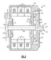
- the output 20 of the electric motor 18 comprises an output shaft 66 that is co-axial with the wheel drive shaft 14.
- the electric motor 18 includes stator laminations 70 that are fixed to the motor housing 40 and rotor laminations 72 that are mounted for rotation with the output shaft 66. Operation of the electric motor 18 due to interaction between the stator 70 and rotor 72 laminations is as known and will not be discussed in further detail.
- the output shaft 66 is rotatably supported for rotation relative to the motor housing 40 by a pair of bearings 74.
- One bearing 74 is positioned at an outboard end 76 of the output shaft 66 and one bearing is positioned at an inboard end 78 of the output shaft 66.
- the electric motor 18 also includes a planetary gear set 80 that that is enclosed within the motor housing 40.
- the planetary gear set 80 includes a sun gear 82 that is directly fixed for rotation with the output shaft 66.
- a plurality of planet gears 84 are in direct meshing engagement with the sun gear 82.
- Each of the planet gears 84 is in direct meshing engagement with a ring gear 86 that is fixed to the motor housing 40.
- the planet gears 84 are supported on a planet carrier 88 via a plurality of planet pins 90.
- the output shaft 66 drives the sun gear 82, which drives the planet gears 84 about the ring gear 86, causing the planet carrier 88 to rotate.
- the planet carrier 88 thus provides the driving output to the wheel drive shaft 14.
- the planet carrier 88 includes a female connection portion 92 that is coupled to a male connection portion 94 ( Figure 1) of the wheel drive shaft 14. It should be understood that these male and female connections could also be reversed.
- a cover 96 encloses the planetary gear set 80 within the motor housing 40.
- the female connection portion 92 is supported for rotation relative to the cover 96 via a third bearing 98.
- the electric motor 18 also drives a rotating parking brake component 34.
- the rotating parking brake component 34 is fixed for rotation with the output shaft 66.
- the planetary gear set 80 is supported by the outboard end 76 of the output shaft 66 and the rotating parking brake component 34 is supported by the inboard end 78 of the output shaft 66.
- the non-rotating brake component 36 is preferably mounted to the motor housing 40.
- Electronics/sensors 100 such as an encoder, for example, are associated with the output shaft 66 for monitoring/controlling motor characteristics.
- the electronics/sensors 100 are enclosed by a cover 102 that is mounted to the motor housing 40.
- the subject invention provides significant advantages over traditional transverse motor mount configurations.
- a shorter, but larger diameter, motor with a built-in single stage planetary gear drive can be used to provide a more compact and simplified mounting configuration where the motor output and wheel drive axes are co-axial.
- this compact configuration provides a motor that can be mounted within an envelope of 17 inches by 13 inches, which is significantly smaller than prior designs, and which is easily mounted within an envelope defined by an outer circumference of the vehicle wheel.
- the use of the motor housing as a structural member of the suspension also provides additional benefits as described above.
- the subjection invention provides a significantly lower cost, reduced size, and reduced weight configuration compared to prior configurations.
Landscapes
- Engineering & Computer Science (AREA)
- Mechanical Engineering (AREA)
- Chemical & Material Sciences (AREA)
- Combustion & Propulsion (AREA)
- Transportation (AREA)
- Arrangement Or Mounting Of Propulsion Units For Vehicles (AREA)
Applications Claiming Priority (1)
| Application Number | Priority Date | Filing Date | Title |
|---|---|---|---|
| US11/511,825 US7686315B2 (en) | 2006-08-29 | 2006-08-29 | Wheel drive motor and trailing arm suspension |
Publications (3)
| Publication Number | Publication Date |
|---|---|
| EP1894762A2 true EP1894762A2 (de) | 2008-03-05 |
| EP1894762A3 EP1894762A3 (de) | 2011-10-26 |
| EP1894762B1 EP1894762B1 (de) | 2015-10-07 |
Family
ID=38769921
Family Applications (1)
| Application Number | Title | Priority Date | Filing Date |
|---|---|---|---|
| EP07253402.7A Active EP1894762B1 (de) | 2006-08-29 | 2007-08-29 | Radantriebsmotor und Längslenkeraufhängung |
Country Status (2)
| Country | Link |
|---|---|
| US (1) | US7686315B2 (de) |
| EP (1) | EP1894762B1 (de) |
Cited By (7)
| Publication number | Priority date | Publication date | Assignee | Title |
|---|---|---|---|---|
| WO2011015277A1 (de) * | 2009-08-06 | 2011-02-10 | Dr. Ing. H.C. F. Porsche Ag | Fahrwerk für ein kraftfahrzeug mit einer elektrische maschinen aufweisenden portalachse |
| WO2011095152A3 (de) * | 2010-02-07 | 2011-10-13 | Ksm Castings Gmbh | Achsmodul |
| NL2005713C2 (nl) * | 2010-11-18 | 2012-05-22 | Gemert Mobile Systems B V Van | Wielophanging en voertuig voorzien van een dergelijke wielophanging. |
| DE102011082391A1 (de) * | 2011-09-09 | 2013-03-14 | Zf Friedrichshafen Ag | Antriebseinheit für ein Elektrofahrzeug sowie Verfahren zum Festlegen einer Antriebseinheit in einem Elektrofahrzeug |
| CN106114102A (zh) * | 2016-07-12 | 2016-11-16 | 崔凤玲 | 万向调节型拖车车轮独立悬挂机构 |
| IT201900015213A1 (it) * | 2019-08-29 | 2021-03-01 | Iveco Spa | Veicolo pesante |
| EP3789218A1 (de) * | 2019-09-03 | 2021-03-10 | Iveco S.p.A. | Antriebsachse für ein schweres hybridfahrzeug |
Families Citing this family (12)
| Publication number | Priority date | Publication date | Assignee | Title |
|---|---|---|---|---|
| DE102005034278A1 (de) * | 2005-07-22 | 2007-04-12 | Daimlerchrysler Ag | Antriebseinheit für ein Fahrzeug |
| CN102612614B (zh) * | 2009-11-16 | 2015-05-13 | 雷米技术有限公司 | 具有行星齿轮组的电动机 |
| KR101104006B1 (ko) * | 2009-12-03 | 2012-01-06 | 현대자동차주식회사 | 차량의 리어 서스펜션 |
| DE102011005616A1 (de) | 2011-03-16 | 2012-09-20 | Zf Friedrichshafen Ag | Antriebsvorrichtung zum Antreiben eines Rades für ein elektrisch antreibbares Fahrzeug |
| JP5932581B2 (ja) * | 2012-09-12 | 2016-06-08 | Ntn株式会社 | インホイールモータ駆動装置のサスペンション構造 |
| KR101462790B1 (ko) * | 2013-06-21 | 2014-11-20 | 현대위아 주식회사 | 전기 자동차용 리어 서스펜션 장착 구조 |
| CN103692895A (zh) * | 2013-12-02 | 2014-04-02 | 同济大学 | 一种新型单纵臂悬架轮边电驱动系统 |
| DE102016006536B4 (de) * | 2016-05-27 | 2018-03-15 | Audi Ag | Elektrische Antriebseinheit für ein Rad eines Kraftfahrzeugs sowie Radaufhängung für die Räder einer Achse eines Kraftfahrzeugs |
| DE102018217347A1 (de) * | 2018-09-12 | 2020-03-12 | Ziehl-Abegg Automotive Gmbh & Co. Kg | Radaufhängung und Schwinge für ein über einen elektrischen oder pneumatischen Motor angetriebenes Rad |
| DE102018217345A1 (de) * | 2018-09-12 | 2020-03-12 | Ziehl-Abegg Automotive Gmbh & Co. Kg | Radaufhängung und Schwinge für ein über einen elektrischen oder pneumatischen Motor angetriebenes Rad |
| KR102795218B1 (ko) * | 2019-12-26 | 2025-04-14 | 엘지전자 주식회사 | 인휠모터 |
| CN119239292A (zh) * | 2024-11-06 | 2025-01-03 | 一汽解放汽车有限公司 | 电驱桥总成、换挡方法及电驱桥工作方法 |
Family Cites Families (18)
| Publication number | Priority date | Publication date | Assignee | Title |
|---|---|---|---|---|
| US1509411A (en) * | 1921-04-21 | 1924-09-23 | Joseph A Anglada | Reduction gearing |
| US1540526A (en) * | 1922-03-16 | 1925-06-02 | Joseph A Anglada | Motor vehicle |
| US1495238A (en) * | 1922-03-16 | 1924-05-27 | Joseph A Anglada | Reduction gearing for motor vehicles |
| US1543044A (en) * | 1922-03-16 | 1925-06-23 | Electrocar Corp | Motor mounting and power-transmission mechanism for motor vehicles |
| JPS54172415U (de) * | 1978-05-24 | 1979-12-05 | ||
| US4330045A (en) * | 1979-09-14 | 1982-05-18 | Reliance Electric Company | Vehicle wheel mechanism |
| US4695073A (en) * | 1986-04-11 | 1987-09-22 | Specialty Products, Inc. | Toe and camber adjusting system |
| US4843910A (en) * | 1987-10-19 | 1989-07-04 | Unit Rig & Equipment | Pinion gear speed disc brake |
| US4878401A (en) * | 1988-09-02 | 1989-11-07 | Jackson Chung | Combination accessory drive and speed reducer |
| FR2679842A1 (fr) * | 1991-07-29 | 1993-02-05 | Shm Management Services Ag | Module de roulement moteur, notamment pour vehicule automobile. |
| US5472059A (en) * | 1994-02-15 | 1995-12-05 | Dana Corporation | Wheel end assembly |
| DE19932586A1 (de) * | 1999-07-13 | 2001-04-12 | Zahnradfabrik Friedrichshafen | Achse mit einer unterhalb der Radachse angeordneten Achsbrücke |
| US6590306B2 (en) * | 2001-02-26 | 2003-07-08 | Yamaha Hatsudoki Kabushiki Kaisha | Electric motor driven wheel |
| WO2003057529A2 (en) * | 2002-01-08 | 2003-07-17 | Hypercar, Inc. | Advanced composite hybrid-electric vehicle |
| US6904988B2 (en) * | 2002-12-27 | 2005-06-14 | Arvinmeritor Technology, Llc | Suspended wheel end powered through trailing arm |
| DE10321878B4 (de) * | 2003-05-15 | 2005-04-28 | Daimler Chrysler Ag | Einzelradaufhängung mit elastischer Radträgerlagerung |
| DE10361296A1 (de) * | 2003-12-24 | 2005-07-21 | Robert Bosch Gmbh | Selbstverstärkende elektromechanische Fahrzeugbremse |
| JP4496474B2 (ja) * | 2004-12-28 | 2010-07-07 | 株式会社デンソー | 電動車輪構造 |
-
2006
- 2006-08-29 US US11/511,825 patent/US7686315B2/en active Active
-
2007
- 2007-08-29 EP EP07253402.7A patent/EP1894762B1/de active Active
Non-Patent Citations (1)
| Title |
|---|
| None |
Cited By (8)
| Publication number | Priority date | Publication date | Assignee | Title |
|---|---|---|---|---|
| WO2011015277A1 (de) * | 2009-08-06 | 2011-02-10 | Dr. Ing. H.C. F. Porsche Ag | Fahrwerk für ein kraftfahrzeug mit einer elektrische maschinen aufweisenden portalachse |
| WO2011095152A3 (de) * | 2010-02-07 | 2011-10-13 | Ksm Castings Gmbh | Achsmodul |
| NL2005713C2 (nl) * | 2010-11-18 | 2012-05-22 | Gemert Mobile Systems B V Van | Wielophanging en voertuig voorzien van een dergelijke wielophanging. |
| DE102011082391A1 (de) * | 2011-09-09 | 2013-03-14 | Zf Friedrichshafen Ag | Antriebseinheit für ein Elektrofahrzeug sowie Verfahren zum Festlegen einer Antriebseinheit in einem Elektrofahrzeug |
| CN106114102A (zh) * | 2016-07-12 | 2016-11-16 | 崔凤玲 | 万向调节型拖车车轮独立悬挂机构 |
| IT201900015213A1 (it) * | 2019-08-29 | 2021-03-01 | Iveco Spa | Veicolo pesante |
| EP3785949A1 (de) * | 2019-08-29 | 2021-03-03 | Iveco S.p.A. | Antriebsanordnung für ein schweres fahrzeug |
| EP3789218A1 (de) * | 2019-09-03 | 2021-03-10 | Iveco S.p.A. | Antriebsachse für ein schweres hybridfahrzeug |
Also Published As
| Publication number | Publication date |
|---|---|
| US20080053725A1 (en) | 2008-03-06 |
| EP1894762A3 (de) | 2011-10-26 |
| EP1894762B1 (de) | 2015-10-07 |
| US7686315B2 (en) | 2010-03-30 |
Similar Documents
| Publication | Publication Date | Title |
|---|---|---|
| EP1894762B1 (de) | Radantriebsmotor und Längslenkeraufhängung | |
| US7314105B2 (en) | Electric drive axle assembly with independent dual motors | |
| US7845445B2 (en) | Electric powertrain system with planetary drive | |
| JP5285722B2 (ja) | 電気アクスルを有する自動車用シャーシ | |
| US6978853B2 (en) | Axle assembly with parallel mounted electric motors | |
| US7350606B2 (en) | Double reduction electric drive wheel assembly | |
| CN103459181B (zh) | 用于能电驱动的车辆的用来驱动车轮的驱动装置 | |
| US6991571B2 (en) | Variable ratio drive system | |
| US7112155B2 (en) | Directly driven driving axle having two drive motors | |
| CN103718434B (zh) | 用于汽车的靠近车轮的驱动单元 | |
| JP2012532061A (ja) | 電気機械を具備するポータルアクスルを備えた自動車用推進装置 | |
| US20050272547A1 (en) | Drive axle assembly for hybrid electric vehicle | |
| KR100717306B1 (ko) | 하이브리드 차량용 동력전달장치 | |
| US12319254B2 (en) | Actuator for brake device | |
| US20230382356A1 (en) | Axle assembly having a differential brake | |
| US7204339B2 (en) | Vehicle wheel end assembly with wheel adapter | |
| CN215267953U (zh) | 一种轮毂电机及车 | |
| CN207015161U (zh) | 电动汽车动力总成 | |
| US20140302958A1 (en) | Drive device having an electrical drive machine | |
| KR20100047522A (ko) | 전기 자동차용 파워 트레인 모듈 | |
| JPH079860A (ja) | 単輪駆動装置 | |
| CN210246535U (zh) | 一种电驱动总成及电动汽车 |
Legal Events
| Date | Code | Title | Description |
|---|---|---|---|
| PUAI | Public reference made under article 153(3) epc to a published international application that has entered the european phase |
Free format text: ORIGINAL CODE: 0009012 |
|
| AK | Designated contracting states |
Kind code of ref document: A2 Designated state(s): AT BE BG CH CY CZ DE DK EE ES FI FR GB GR HU IE IS IT LI LT LU LV MC MT NL PL PT RO SE SI SK TR |
|
| AX | Request for extension of the european patent |
Extension state: AL BA HR MK YU |
|
| PUAL | Search report despatched |
Free format text: ORIGINAL CODE: 0009013 |
|
| AK | Designated contracting states |
Kind code of ref document: A3 Designated state(s): AT BE BG CH CY CZ DE DK EE ES FI FR GB GR HU IE IS IT LI LT LU LV MC MT NL PL PT RO SE SI SK TR |
|
| AX | Request for extension of the european patent |
Extension state: AL BA HR MK RS |
|
| RIC1 | Information provided on ipc code assigned before grant |
Ipc: B60G 3/14 20060101ALI20110916BHEP Ipc: B60K 7/00 20060101AFI20110916BHEP |
|
| 17P | Request for examination filed |
Effective date: 20120413 |
|
| AKX | Designation fees paid |
Designated state(s): AT BE BG CH CY CZ DE DK EE ES FI FR GB GR HU IE IS IT LI LT LU LV MC MT NL PL PT RO SE SI SK TR |
|
| 17Q | First examination report despatched |
Effective date: 20131220 |
|
| GRAP | Despatch of communication of intention to grant a patent |
Free format text: ORIGINAL CODE: EPIDOSNIGR1 |
|
| INTG | Intention to grant announced |
Effective date: 20150428 |
|
| GRAS | Grant fee paid |
Free format text: ORIGINAL CODE: EPIDOSNIGR3 |
|
| GRAA | (expected) grant |
Free format text: ORIGINAL CODE: 0009210 |
|
| AK | Designated contracting states |
Kind code of ref document: B1 Designated state(s): AT BE BG CH CY CZ DE DK EE ES FI FR GB GR HU IE IS IT LI LT LU LV MC MT NL PL PT RO SE SI SK TR |
|
| REG | Reference to a national code |
Ref country code: GB Ref legal event code: FG4D |
|
| REG | Reference to a national code |
Ref country code: AT Ref legal event code: REF Ref document number: 753520 Country of ref document: AT Kind code of ref document: T Effective date: 20151015 Ref country code: CH Ref legal event code: EP |
|
| REG | Reference to a national code |
Ref country code: IE Ref legal event code: FG4D |
|
| REG | Reference to a national code |
Ref country code: DE Ref legal event code: R096 Ref document number: 602007043382 Country of ref document: DE |
|
| REG | Reference to a national code |
Ref country code: SE Ref legal event code: TRGR |
|
| REG | Reference to a national code |
Ref country code: AT Ref legal event code: MK05 Ref document number: 753520 Country of ref document: AT Kind code of ref document: T Effective date: 20151007 |
|
| REG | Reference to a national code |
Ref country code: NL Ref legal event code: FP |
|
| REG | Reference to a national code |
Ref country code: LT Ref legal event code: MG4D |
|
| PG25 | Lapsed in a contracting state [announced via postgrant information from national office to epo] |
Ref country code: LT Free format text: LAPSE BECAUSE OF FAILURE TO SUBMIT A TRANSLATION OF THE DESCRIPTION OR TO PAY THE FEE WITHIN THE PRESCRIBED TIME-LIMIT Effective date: 20151007 Ref country code: IS Free format text: LAPSE BECAUSE OF FAILURE TO SUBMIT A TRANSLATION OF THE DESCRIPTION OR TO PAY THE FEE WITHIN THE PRESCRIBED TIME-LIMIT Effective date: 20160207 Ref country code: IT Free format text: LAPSE BECAUSE OF FAILURE TO SUBMIT A TRANSLATION OF THE DESCRIPTION OR TO PAY THE FEE WITHIN THE PRESCRIBED TIME-LIMIT Effective date: 20151007 Ref country code: ES Free format text: LAPSE BECAUSE OF FAILURE TO SUBMIT A TRANSLATION OF THE DESCRIPTION OR TO PAY THE FEE WITHIN THE PRESCRIBED TIME-LIMIT Effective date: 20151007 |
|
| PG25 | Lapsed in a contracting state [announced via postgrant information from national office to epo] |
Ref country code: FI Free format text: LAPSE BECAUSE OF FAILURE TO SUBMIT A TRANSLATION OF THE DESCRIPTION OR TO PAY THE FEE WITHIN THE PRESCRIBED TIME-LIMIT Effective date: 20151007 Ref country code: PT Free format text: LAPSE BECAUSE OF FAILURE TO SUBMIT A TRANSLATION OF THE DESCRIPTION OR TO PAY THE FEE WITHIN THE PRESCRIBED TIME-LIMIT Effective date: 20160208 Ref country code: PL Free format text: LAPSE BECAUSE OF FAILURE TO SUBMIT A TRANSLATION OF THE DESCRIPTION OR TO PAY THE FEE WITHIN THE PRESCRIBED TIME-LIMIT Effective date: 20151007 Ref country code: AT Free format text: LAPSE BECAUSE OF FAILURE TO SUBMIT A TRANSLATION OF THE DESCRIPTION OR TO PAY THE FEE WITHIN THE PRESCRIBED TIME-LIMIT Effective date: 20151007 Ref country code: LV Free format text: LAPSE BECAUSE OF FAILURE TO SUBMIT A TRANSLATION OF THE DESCRIPTION OR TO PAY THE FEE WITHIN THE PRESCRIBED TIME-LIMIT Effective date: 20151007 Ref country code: GR Free format text: LAPSE BECAUSE OF FAILURE TO SUBMIT A TRANSLATION OF THE DESCRIPTION OR TO PAY THE FEE WITHIN THE PRESCRIBED TIME-LIMIT Effective date: 20160108 |
|
| REG | Reference to a national code |
Ref country code: DE Ref legal event code: R097 Ref document number: 602007043382 Country of ref document: DE |
|
| PG25 | Lapsed in a contracting state [announced via postgrant information from national office to epo] |
Ref country code: CZ Free format text: LAPSE BECAUSE OF FAILURE TO SUBMIT A TRANSLATION OF THE DESCRIPTION OR TO PAY THE FEE WITHIN THE PRESCRIBED TIME-LIMIT Effective date: 20151007 |
|
| PLBE | No opposition filed within time limit |
Free format text: ORIGINAL CODE: 0009261 |
|
| STAA | Information on the status of an ep patent application or granted ep patent |
Free format text: STATUS: NO OPPOSITION FILED WITHIN TIME LIMIT |
|
| REG | Reference to a national code |
Ref country code: FR Ref legal event code: PLFP Year of fee payment: 10 |
|
| PG25 | Lapsed in a contracting state [announced via postgrant information from national office to epo] |
Ref country code: DK Free format text: LAPSE BECAUSE OF FAILURE TO SUBMIT A TRANSLATION OF THE DESCRIPTION OR TO PAY THE FEE WITHIN THE PRESCRIBED TIME-LIMIT Effective date: 20151007 Ref country code: EE Free format text: LAPSE BECAUSE OF FAILURE TO SUBMIT A TRANSLATION OF THE DESCRIPTION OR TO PAY THE FEE WITHIN THE PRESCRIBED TIME-LIMIT Effective date: 20151007 Ref country code: SK Free format text: LAPSE BECAUSE OF FAILURE TO SUBMIT A TRANSLATION OF THE DESCRIPTION OR TO PAY THE FEE WITHIN THE PRESCRIBED TIME-LIMIT Effective date: 20151007 Ref country code: RO Free format text: LAPSE BECAUSE OF FAILURE TO SUBMIT A TRANSLATION OF THE DESCRIPTION OR TO PAY THE FEE WITHIN THE PRESCRIBED TIME-LIMIT Effective date: 20151007 |
|
| 26N | No opposition filed |
Effective date: 20160708 |
|
| PG25 | Lapsed in a contracting state [announced via postgrant information from national office to epo] |
Ref country code: SI Free format text: LAPSE BECAUSE OF FAILURE TO SUBMIT A TRANSLATION OF THE DESCRIPTION OR TO PAY THE FEE WITHIN THE PRESCRIBED TIME-LIMIT Effective date: 20151007 |
|
| PG25 | Lapsed in a contracting state [announced via postgrant information from national office to epo] |
Ref country code: BE Free format text: LAPSE BECAUSE OF FAILURE TO SUBMIT A TRANSLATION OF THE DESCRIPTION OR TO PAY THE FEE WITHIN THE PRESCRIBED TIME-LIMIT Effective date: 20151007 |
|
| PG25 | Lapsed in a contracting state [announced via postgrant information from national office to epo] |
Ref country code: MC Free format text: LAPSE BECAUSE OF FAILURE TO SUBMIT A TRANSLATION OF THE DESCRIPTION OR TO PAY THE FEE WITHIN THE PRESCRIBED TIME-LIMIT Effective date: 20151007 |
|
| REG | Reference to a national code |
Ref country code: CH Ref legal event code: PL |
|
| GBPC | Gb: european patent ceased through non-payment of renewal fee |
Effective date: 20160829 |
|
| PG25 | Lapsed in a contracting state [announced via postgrant information from national office to epo] |
Ref country code: CH Free format text: LAPSE BECAUSE OF NON-PAYMENT OF DUE FEES Effective date: 20160831 Ref country code: LI Free format text: LAPSE BECAUSE OF NON-PAYMENT OF DUE FEES Effective date: 20160831 |
|
| REG | Reference to a national code |
Ref country code: IE Ref legal event code: MM4A |
|
| PG25 | Lapsed in a contracting state [announced via postgrant information from national office to epo] |
Ref country code: GB Free format text: LAPSE BECAUSE OF NON-PAYMENT OF DUE FEES Effective date: 20160829 Ref country code: IE Free format text: LAPSE BECAUSE OF NON-PAYMENT OF DUE FEES Effective date: 20160829 |
|
| REG | Reference to a national code |
Ref country code: FR Ref legal event code: PLFP Year of fee payment: 11 |
|
| PG25 | Lapsed in a contracting state [announced via postgrant information from national office to epo] |
Ref country code: LU Free format text: LAPSE BECAUSE OF NON-PAYMENT OF DUE FEES Effective date: 20160829 |
|
| PG25 | Lapsed in a contracting state [announced via postgrant information from national office to epo] |
Ref country code: CY Free format text: LAPSE BECAUSE OF FAILURE TO SUBMIT A TRANSLATION OF THE DESCRIPTION OR TO PAY THE FEE WITHIN THE PRESCRIBED TIME-LIMIT Effective date: 20151007 Ref country code: HU Free format text: LAPSE BECAUSE OF FAILURE TO SUBMIT A TRANSLATION OF THE DESCRIPTION OR TO PAY THE FEE WITHIN THE PRESCRIBED TIME-LIMIT; INVALID AB INITIO Effective date: 20070829 |
|
| PG25 | Lapsed in a contracting state [announced via postgrant information from national office to epo] |
Ref country code: TR Free format text: LAPSE BECAUSE OF FAILURE TO SUBMIT A TRANSLATION OF THE DESCRIPTION OR TO PAY THE FEE WITHIN THE PRESCRIBED TIME-LIMIT Effective date: 20151007 Ref country code: MT Free format text: LAPSE BECAUSE OF NON-PAYMENT OF DUE FEES Effective date: 20160831 |
|
| PG25 | Lapsed in a contracting state [announced via postgrant information from national office to epo] |
Ref country code: BG Free format text: LAPSE BECAUSE OF FAILURE TO SUBMIT A TRANSLATION OF THE DESCRIPTION OR TO PAY THE FEE WITHIN THE PRESCRIBED TIME-LIMIT Effective date: 20151007 |
|
| REG | Reference to a national code |
Ref country code: FR Ref legal event code: PLFP Year of fee payment: 12 |
|
| P01 | Opt-out of the competence of the unified patent court (upc) registered |
Effective date: 20230531 |
|
| PGFP | Annual fee paid to national office [announced via postgrant information from national office to epo] |
Ref country code: NL Payment date: 20240826 Year of fee payment: 18 |
|
| PGFP | Annual fee paid to national office [announced via postgrant information from national office to epo] |
Ref country code: DE Payment date: 20250827 Year of fee payment: 19 |
|
| PGFP | Annual fee paid to national office [announced via postgrant information from national office to epo] |
Ref country code: FR Payment date: 20250825 Year of fee payment: 19 |
|
| PGFP | Annual fee paid to national office [announced via postgrant information from national office to epo] |
Ref country code: SE Payment date: 20250827 Year of fee payment: 19 |
|
| REG | Reference to a national code |
Ref country code: NL Ref legal event code: MM Effective date: 20250901 |