EP1894774B1 - Ladungssicherungssystem und entsprechendes Einbauverfahren - Google Patents
Ladungssicherungssystem und entsprechendes Einbauverfahren Download PDFInfo
- Publication number
- EP1894774B1 EP1894774B1 EP06119987A EP06119987A EP1894774B1 EP 1894774 B1 EP1894774 B1 EP 1894774B1 EP 06119987 A EP06119987 A EP 06119987A EP 06119987 A EP06119987 A EP 06119987A EP 1894774 B1 EP1894774 B1 EP 1894774B1
- Authority
- EP
- European Patent Office
- Prior art keywords
- rails
- load securing
- vehicle
- rail
- securing system
- Prior art date
- Legal status (The legal status is an assumption and is not a legal conclusion. Google has not performed a legal analysis and makes no representation as to the accuracy of the status listed.)
- Not-in-force
Links
- 238000000034 method Methods 0.000 title claims abstract description 10
- 239000002184 metal Substances 0.000 claims description 6
- 230000001902 propagating effect Effects 0.000 claims description 3
- 239000002023 wood Substances 0.000 claims description 3
- 239000002131 composite material Substances 0.000 claims description 2
- 238000010276 construction Methods 0.000 description 9
- 239000000463 material Substances 0.000 description 4
- 230000006378 damage Effects 0.000 description 3
- 238000009434 installation Methods 0.000 description 3
- 230000001133 acceleration Effects 0.000 description 1
- 230000000295 complement effect Effects 0.000 description 1
- 230000001419 dependent effect Effects 0.000 description 1
- 238000001125 extrusion Methods 0.000 description 1
- 230000003993 interaction Effects 0.000 description 1
- 238000004519 manufacturing process Methods 0.000 description 1
- 230000000149 penetrating effect Effects 0.000 description 1
Images


Classifications
-
- B—PERFORMING OPERATIONS; TRANSPORTING
- B60—VEHICLES IN GENERAL
- B60R—VEHICLES, VEHICLE FITTINGS, OR VEHICLE PARTS, NOT OTHERWISE PROVIDED FOR
- B60R11/00—Arrangements for holding or mounting articles, not otherwise provided for
- B60R11/06—Arrangements for holding or mounting articles, not otherwise provided for for tools or spare parts
-
- B—PERFORMING OPERATIONS; TRANSPORTING
- B60—VEHICLES IN GENERAL
- B60P—VEHICLES ADAPTED FOR LOAD TRANSPORTATION OR TO TRANSPORT, TO CARRY, OR TO COMPRISE SPECIAL LOADS OR OBJECTS
- B60P7/00—Securing or covering of load on vehicles
- B60P7/06—Securing of load
- B60P7/08—Securing to the vehicle floor or sides
- B60P7/0807—Attachment points
- B60P7/0815—Attachment rails or trellis
-
- B—PERFORMING OPERATIONS; TRANSPORTING
- B60—VEHICLES IN GENERAL
- B60P—VEHICLES ADAPTED FOR LOAD TRANSPORTATION OR TO TRANSPORT, TO CARRY, OR TO COMPRISE SPECIAL LOADS OR OBJECTS
- B60P3/00—Vehicles adapted to transport, to carry or to comprise special loads or objects
- B60P3/14—Vehicles adapted to transport, to carry or to comprise special loads or objects the object being a workshop for servicing, for maintenance, or for carrying workmen during work
Definitions
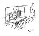
- the present invention relates to a load securing system, for a cargo or a back space in an automotive vehicle, according to the preamble of claim 1. Furthermore, the present invention is related to a method of installing such a system, according to claim 17.
- the cargo space of the vehicle is provided with an inner floor, usually made of wood, but the floor might also be made of for example an artificial, plastic material. This floor functions as a good support to work, stand and walk upon and is also used as an anchor plate for the module unit.
- the module system is often also at least partly attached to the wall and the purpose is to counteract that the unit tip for example in a turn. It is common practise to secure the module unit/units to the wall with two fasteners, with screws or the like penetrating said vehicle wall, one fastener being positioned on the first side portion of the module unit and one fastener on the other side portion of same module unit.
- the module system or maybe one module unit thereof, can break away which may cause damages.
- the module units in particular when they are equipped with tools and material which are included in a toolkit, are usually rather heavy and may in such case present a potential safety risk.
- the module system may, if not securely attached, move forward with a large force and which in a serious scenario may break through into the driver cabin and thereby even cause personal injuries. Therefore, an improved arrangement for safe fastening of the module unit is needed.
- WO2006057596 discloses a fastening device for working equipment in a vehicle, which comprises a fastenings device further comprising a floor bracket plate, provided with fixation points.
- an objective of the invention as defined in the claim 1 is to solve or at least reduce the problems discussed above.
- a row of module units is formed by placing modules next to one another in the longitudinal direction of the vehicle and they are then fixed to the floor and the wall with respective two fastening devices.
- the solution will spread out the forces, in case of any impact, through fastening zones over the whole row of module units or e.g. one large unit instead of just one point at each side portions.
- said rails are propagating parallel to one another along the longitudinal direction of the vehicle.
- At least one module system containing for example work equipment, is placed along the longitudinal direction of the vehicle and attached to one rail.
- a first fastener is arranged and at a second side portion of said module system a second fastener is arranged, said fasteners arranging the module system to the wall of the vehicle.
- a wall rail is positioned by said wall along the longitudinal direction of the vehicle and comprises fastening zones for the module system, said rail being formed for variable positioning of at least three fasteners for distribution of module system loading along said rail.
- At least one additional fastening zone is positioned between a first and a second fastening zone of the side portions of the module system.
- At least one of the rails is made of metal.
- at least one of the rail has at least one undercut profile.
- at least one of the rails has three rail sections.
- at least one of the rails is advantageously adapted for tongue and groove engagement with said bridging element along a first groove.
- at least one of the rails is adapted for tongue and groove engagement with said bridging element along a first and a second groove.
- the bridging element is formed by at least one floor element .
- a plurality of floor elements forms the bridging element. The upper side of the bridging element and the upper side of the rail are levelled once mounted.
- the bridging element (33) is made of wood. It is also an option to use a composite material. However, it is realized that the claimed invention is not limited to the use of a particular material.
- the bridging element is provided with a mat on the upper side. This presents a further way of adapting the material to provide appropriate working conditions.
- a method of installing a load securing system in service vehicles comprising the steps of, connecting a bridging element with a rail on two sides of said bridging element, placing bridging element and rails in a cargo space floor of said vehicle and arranging said rails through fasteners to the vehicle at a side of each rail facing away from said bridging element, thereby fixing said load securing system in the service vehicle.
- floor levelling sections are positioned on vehicle floor spaces in the cargo space, in order to achieve a levelled surface throughout the entire cargo floor level.
- a module system is positioned anchored to said rail of the load securing system.
- a module system is fixed to an additional rail previously mounted on the wall of the service vehicle.
- module systems comprise module units of various types. It is realized that module units may encompass many types of cupboards, tool holders, shelves, rack systems or other module units.
- the module system is furthermore based on that a rail is arranged to the wall along the longitudinal direction of the vehicle and the rail has fastening zones on which fasteners can be arranged. In this way the stress forces can be spread from being rather at two points to be distributed over the entire rail.
- the rail which is fixated on the wall is preferably made of metal and is preferably formed from a metal sheet or through extrusion.
- the rail has at least one undercut channel which comprise the fastening zone for the module unit, wherein holes with a defined diameter and at a defined distance are arranged. These holes give the possibility to screw the rail to the wall, the rail can also be fastened with a double-stick tape.
- one additional fastening zone is arranged between a first and a second fastening zone of the side portions of the module unit.
- the wall rail has at least one undercut channel for enabling the stepless manoeuvrability.
- the wall rail has three undercut channels.
- the fastening zones comprise a fastener, which is arranged to the wall rail, preferably through joint connection elements.
- the rail is adapted for complementary engagement with a fastener.
- the fastener is of quick-fastening type.
- the fastener is a bracket with at least a part propagating in a perpendicular direction in relation to said rail.
Landscapes
- Engineering & Computer Science (AREA)
- Mechanical Engineering (AREA)
- Transportation (AREA)
- Body Structure For Vehicles (AREA)
- Fittings On The Vehicle Exterior For Carrying Loads, And Devices For Holding Or Mounting Articles (AREA)
- Alarm Systems (AREA)
- Connection Of Plates (AREA)
Claims (20)
- Lastsicherungssystem für einen Fracht- oder Rückraum in einem Kraftfahrzeug (10), wobei zumindest zwei Schienen (2) derart angeordnet sind, dass sie diesen Raum entlang befestigbar sind, wobei die Schienen (2) durch ein Brückenelement (33) miteinander verbindbar sind, das in einem Raum zwischen den Schienen (2) angeordnet ist, und wobei im Gebrauch des Systems jede Schiene (2) durch ein oder mehr Befestigungsmittel (32) gehalten ist, das mit dem Fahrzeug (10) verbunden ist, dadurch gekennzeichnet, dass jedes Befestigungsmittel (32) im Gebrauch über ein Befestigungselement (31) mit dem Fahrzeug (10) verbunden ist, das sich an einer Seite der entsprechenden Schiene (2) von dem Brückenelement (33) weggekehrt befindet.
- Lastsicherungssystem nach Anspruch 1, wobei die Schienen (2) im Gebrauch parallel zueinander entlang der Längsrichtung des Fahrzeugs (10) verlaufen.
- Lastsicherungssystem nach einem der Ansprüche 1 oder 2, umfassend zumindest ein Modulsystem (1) zum Enthalten von beispielsweise Werkzeugausrüstung, wobei im Gebrauch das Modulsystem (1) entlang der Längsrichtung des Fahrzeugs (10) angeordnet und an einer der Schienen angebracht ist.
- Lastsicherungssystem nach Anspruch 3, wobei an einem ersten Seitenabschnitt des Modulsystems (1) ein erstes Befestigungselement angeordnet ist und an einem zweiten Seitenabschnitt des Modulsystems ein zweites Befestigungselement angeordnet ist, wobei die Befestigungselemente im Gebrauch das Modulsystem an der Wand des Fahrzeugs (10) anordnen.
- Lastsicherungssystem nach Anspruch 3, umfassend eine zusätzliche Schiene (52), die im Gebrauch durch die Wand entlang der Längsrichtung des Fahrzeugs (10) positioniert ist und Befestigungsbereiche (64) für das Modulsystem (1) umfasst, wobei die zusätzliche Schine (52) zum variablen Positionieren von zumindest drei Befestigungselementen (59a, 59b, 59c) zur Verteilung von Modulsystemladung entlang der Schiene (52) ausgebildet ist.
- Lastsicherungssystem nach Anspruch 5, wobei zumindest ein zusätzlicher Befestigungsbereich (64b) zwischen einem ersten (64a) und zweiten (64c) Befestigungsbereich der Seitenabschnitte des Modulsystems (1) positioniert ist.
- Lastsicherungssystem nach einem der Ansprüche 1 bis 6, wobei zumindest eine der Schienen (2) aus Metall hergestellt ist.
- Lastsicherungssystem nach einem der Ansprüche 1 bis 7, wobei zumindest eine der Schienen (2) zumindest ein unterschnittenes Profil (5; 6; 55; 56; 105; 106) aufweist.
- Lastsicherungssystem nach einem der Ansprüche 1 bis 8, wobei zumindest eine der Schienen (2) drei Schienenteilabschnitte (11, 12, 13; 51, 60, 61; 11, 112, 113) aufweist.
- Lastsicherungssystem nach einem der Ansprüche 1 bis 9, wobei zumindest eine der Schienen (2) zum Nut- und Federeingiff mit dem Brückenelement (33) entlang einer ersten Nut (36) geeignet ist.
- Lastsicherungssystem nach einem der Ansprüche 1 bis 10, wobei zumindest eine der Schienen (2) zum Nut- und Federeingiff mit dem Brückenelement (33) entlang einer ersten (36) und einer zweiten Nut (37) geeignet ist.
- Lastsicherungssystem nach einem der Ansprüche 1 bis 11, wobei das Brückenelement (33) ein Bodenteilabschnitt ist.
- Lastsicherungssystem nach einem der Ansprüche 1 bis 11, wobei mehrere Bodenelemente das Brückenelement (33) ausbilden.
- Lastsicherungssystem nach einem der Ansprüche 1 bis 13, wobei die Oberseite des Brückenelements (33) und die Oberseite (5, 6) von zumindest einer der Schienen nach der Anbringung abgeglichen sind.
- Lastsicherungssystem nach einem der Ansprüche 1 bis 14, wobei das Brückenelement (33) aus Holz oder Verbundmaterial hergestellt ist.
- Lastsicherungssystem nach einem der Ansprüche 1 bis 15, wobei das Brückenelement (33) mit einer Matte auf der Oberseite versehen ist.
- Verfahren zum Einrichten eines Lastsicherungssystems in Service-Fahrzeugen, folgende Schritte umfassend:Verbinden eines Brückenelements (33) mit zwei Schienen (2) an zwei gegenüberliegenden Seiten des Brückenelements (33);Anordnen des Brückenelements (33) und der Schienen (2) auf einem Frachtraumboden des Fahrzeugs; undAnordnen der Schienen (2) über Befestigungselemente (31) an dem Fahrzeug auf einer Seite jeder Schiene (2), die von dem Brückenelement (33) weggekehrt ist, wodurch das Lastsicherungssystem in dem Service-Fahrzeug (10) befestigt wird.
- Verfahren nach Anspruch 17, wobei zusätzlich Bodenabgleichteilabschnitte (34) auf den Fahrzeugbodenräumen in dem Frachtraum angeordnet werden, um eine abgeglichene Oberfläche zu erzielen.
- Verfahren nach einem der Ansprüche 17 bis 18, wobei zusätzlich ein Modulsystem (1) mit einer der Schienen (2) verankert angeordnet wird.
- Verfahren nach einem der Ansprüche 17 bis 19, wobei zusätzlich ein Modulsystem (1) an einer zusätzlichen Schine (52) befestigt wird, die vorher an der Wand des Service-Fahrzeugs (10) angebracht wurde.
Priority Applications (4)
| Application Number | Priority Date | Filing Date | Title |
|---|---|---|---|
| EP06119987A EP1894774B1 (de) | 2006-09-01 | 2006-09-01 | Ladungssicherungssystem und entsprechendes Einbauverfahren |
| DE602006018913T DE602006018913D1 (de) | 2006-09-01 | 2006-09-01 | Ladungssicherungssystem und entsprechendes Einbauverfahren |
| AT06119987T ATE491598T1 (de) | 2006-09-01 | 2006-09-01 | Ladungssicherungssystem und entsprechendes einbauverfahren |
| PCT/EP2007/007482 WO2008025500A2 (en) | 2006-09-01 | 2007-08-27 | Load securing system and method for installing such system |
Applications Claiming Priority (1)
| Application Number | Priority Date | Filing Date | Title |
|---|---|---|---|
| EP06119987A EP1894774B1 (de) | 2006-09-01 | 2006-09-01 | Ladungssicherungssystem und entsprechendes Einbauverfahren |
Publications (2)
| Publication Number | Publication Date |
|---|---|
| EP1894774A1 EP1894774A1 (de) | 2008-03-05 |
| EP1894774B1 true EP1894774B1 (de) | 2010-12-15 |
Family
ID=37681681
Family Applications (1)
| Application Number | Title | Priority Date | Filing Date |
|---|---|---|---|
| EP06119987A Not-in-force EP1894774B1 (de) | 2006-09-01 | 2006-09-01 | Ladungssicherungssystem und entsprechendes Einbauverfahren |
Country Status (4)
| Country | Link |
|---|---|
| EP (1) | EP1894774B1 (de) |
| AT (1) | ATE491598T1 (de) |
| DE (1) | DE602006018913D1 (de) |
| WO (1) | WO2008025500A2 (de) |
Families Citing this family (10)
| Publication number | Priority date | Publication date | Assignee | Title |
|---|---|---|---|---|
| EP2965948A1 (de) * | 2014-07-09 | 2016-01-13 | Modul-System HH AB | Bodensystem, Fahrzeug, wie beispielsweise Servicefahrzeuge mit einem solchen Bodensystem und Installation eines solchen Bodensystems |
| EP3078577B1 (de) | 2015-04-09 | 2018-12-19 | Modul-System HH AB | Bodensystem, fahrzeug, wie beispielsweise servicefahrzeuge mit solch einem bodensystem |
| EP3078578A1 (de) | 2015-04-09 | 2016-10-12 | Modul-System HH AB | Bodenpaneelsystem |
| DE102015004337A1 (de) | 2015-04-09 | 2016-10-13 | Modul-System Hh Ab | Bodenplattenteil |
| EP3078544A1 (de) | 2015-04-09 | 2016-10-12 | Modul-System HH AB | Längliche befestigungsschiene |
| EP3106372A1 (de) | 2015-06-17 | 2016-12-21 | Modul-System HH AB | Bodenpaneelsystem |
| EP3322615B1 (de) * | 2015-07-16 | 2019-12-18 | Volvo Truck Corporation | Zusammenlegbare lageranordnung |
| US12187176B1 (en) * | 2020-09-26 | 2025-01-07 | Steelhouse Fabrication, LLC | Frame for modular trailer conversion unit and modular trailer conversion system |
| US20220314865A1 (en) * | 2021-04-06 | 2022-10-06 | Samuel Westlind | Motor vehicle deck |
| FI132027B1 (fi) * | 2024-04-09 | 2026-04-23 | Moor Room Oy | Järjestely ajoneuvon kuormatilan yhteydessä |
Family Cites Families (2)
| Publication number | Priority date | Publication date | Assignee | Title |
|---|---|---|---|---|
| US3159111A (en) * | 1962-05-14 | 1964-12-01 | Puilman Inc | Container attachment device for railway cars |
| US6270137B1 (en) * | 2000-03-03 | 2001-08-07 | J.T. Custom Works Inc. | Track system for customized vehicles and trailers |
-
2006
- 2006-09-01 DE DE602006018913T patent/DE602006018913D1/de active Active
- 2006-09-01 AT AT06119987T patent/ATE491598T1/de not_active IP Right Cessation
- 2006-09-01 EP EP06119987A patent/EP1894774B1/de not_active Not-in-force
-
2007
- 2007-08-27 WO PCT/EP2007/007482 patent/WO2008025500A2/en not_active Ceased
Also Published As
| Publication number | Publication date |
|---|---|
| DE602006018913D1 (de) | 2011-01-27 |
| WO2008025500A2 (en) | 2008-03-06 |
| WO2008025500A3 (en) | 2008-04-17 |
| EP1894774A1 (de) | 2008-03-05 |
| ATE491598T1 (de) | 2011-01-15 |
Similar Documents
| Publication | Publication Date | Title |
|---|---|---|
| WO2008025500A2 (en) | Load securing system and method for installing such system | |
| CA2816268C (en) | Rail mounting system | |
| EP2408648B1 (de) | Sonnendachauskleidungsbefestigungssystem | |
| EP1897757B1 (de) | Ladebettsystem zur Frachtbefestigung | |
| US20180222396A1 (en) | Roof rail for a motor vehicle, motor vehicle having a roof rail, and method for producing a roof rail | |
| EP3233568A1 (de) | Befestigungssystem | |
| CA2702953A1 (en) | Fuselage cell structure of an airplane for the simplified installation and attachment of fasteners for fastening conduits | |
| EP1894773A1 (de) | Modulares System für Einsatz-Fahrzeuge | |
| KR20140034317A (ko) | 자동차 시트의 조절 드라이브용 유지 장치 | |
| US20100090488A1 (en) | Reconfigurable console mount | |
| EP3166821B1 (de) | Bodensystem, fahrzeug, wie beispielsweise servicefahrzeuge mit einem solchen bodensystem und installation eines solchen bodensystems | |
| US10112549B2 (en) | Vehicle ladder mounting system for custom installations | |
| US20190126836A1 (en) | Cargo storage system for a vehicle | |
| EP3112212B1 (de) | Absorbierende schiene | |
| EP3078577B1 (de) | Bodensystem, fahrzeug, wie beispielsweise servicefahrzeuge mit solch einem bodensystem | |
| GB2512335A (en) | Roof rail system | |
| EP3106371B2 (de) | Fussbodensystem | |
| EP3078544A1 (de) | Längliche befestigungsschiene | |
| EP3078548B1 (de) | Speichersystem | |
| EP3106372A1 (de) | Bodenpaneelsystem | |
| GB2450800A (en) | Bracket for supporting a load applied to a ladder | |
| EP3078578A1 (de) | Bodenpaneelsystem | |
| WO2006096102A1 (en) | Hatch for a commercial vehicle |
Legal Events
| Date | Code | Title | Description |
|---|---|---|---|
| PUAI | Public reference made under article 153(3) epc to a published international application that has entered the european phase |
Free format text: ORIGINAL CODE: 0009012 |
|
| AK | Designated contracting states |
Kind code of ref document: A1 Designated state(s): AT BE BG CH CY CZ DE DK EE ES FI FR GB GR HU IE IS IT LI LT LU LV MC NL PL PT RO SE SI SK TR |
|
| AX | Request for extension of the european patent |
Extension state: AL BA HR MK YU |
|
| 17P | Request for examination filed |
Effective date: 20080902 |
|
| 17Q | First examination report despatched |
Effective date: 20081002 |
|
| AKX | Designation fees paid |
Designated state(s): AT BE BG CH CY CZ DE DK EE ES FI FR GB GR HU IE IS IT LI LT LU LV MC NL PL PT RO SE SI SK TR |
|
| GRAP | Despatch of communication of intention to grant a patent |
Free format text: ORIGINAL CODE: EPIDOSNIGR1 |
|
| GRAS | Grant fee paid |
Free format text: ORIGINAL CODE: EPIDOSNIGR3 |
|
| GRAA | (expected) grant |
Free format text: ORIGINAL CODE: 0009210 |
|
| AK | Designated contracting states |
Kind code of ref document: B1 Designated state(s): AT BE BG CH CY CZ DE DK EE ES FI FR GB GR HU IE IS IT LI LT LU LV MC NL PL PT RO SE SI SK TR |
|
| REG | Reference to a national code |
Ref country code: CH Ref legal event code: EP Ref country code: GB Ref legal event code: FG4D |
|
| REG | Reference to a national code |
Ref country code: IE Ref legal event code: FG4D |
|
| REF | Corresponds to: |
Ref document number: 602006018913 Country of ref document: DE Date of ref document: 20110127 Kind code of ref document: P |
|
| REG | Reference to a national code |
Ref country code: SE Ref legal event code: TRGR |
|
| REG | Reference to a national code |
Ref country code: NL Ref legal event code: VDEP Effective date: 20101215 |
|
| PG25 | Lapsed in a contracting state [announced via postgrant information from national office to epo] |
Ref country code: LT Free format text: LAPSE BECAUSE OF FAILURE TO SUBMIT A TRANSLATION OF THE DESCRIPTION OR TO PAY THE FEE WITHIN THE PRESCRIBED TIME-LIMIT Effective date: 20101215 |
|
| LTIE | Lt: invalidation of european patent or patent extension |
Effective date: 20101215 |
|
| PG25 | Lapsed in a contracting state [announced via postgrant information from national office to epo] |
Ref country code: BG Free format text: LAPSE BECAUSE OF FAILURE TO SUBMIT A TRANSLATION OF THE DESCRIPTION OR TO PAY THE FEE WITHIN THE PRESCRIBED TIME-LIMIT Effective date: 20110315 Ref country code: LV Free format text: LAPSE BECAUSE OF FAILURE TO SUBMIT A TRANSLATION OF THE DESCRIPTION OR TO PAY THE FEE WITHIN THE PRESCRIBED TIME-LIMIT Effective date: 20101215 Ref country code: FI Free format text: LAPSE BECAUSE OF FAILURE TO SUBMIT A TRANSLATION OF THE DESCRIPTION OR TO PAY THE FEE WITHIN THE PRESCRIBED TIME-LIMIT Effective date: 20101215 Ref country code: NL Free format text: LAPSE BECAUSE OF FAILURE TO SUBMIT A TRANSLATION OF THE DESCRIPTION OR TO PAY THE FEE WITHIN THE PRESCRIBED TIME-LIMIT Effective date: 20101215 Ref country code: CY Free format text: LAPSE BECAUSE OF FAILURE TO SUBMIT A TRANSLATION OF THE DESCRIPTION OR TO PAY THE FEE WITHIN THE PRESCRIBED TIME-LIMIT Effective date: 20101215 Ref country code: SI Free format text: LAPSE BECAUSE OF FAILURE TO SUBMIT A TRANSLATION OF THE DESCRIPTION OR TO PAY THE FEE WITHIN THE PRESCRIBED TIME-LIMIT Effective date: 20101215 Ref country code: AT Free format text: LAPSE BECAUSE OF FAILURE TO SUBMIT A TRANSLATION OF THE DESCRIPTION OR TO PAY THE FEE WITHIN THE PRESCRIBED TIME-LIMIT Effective date: 20101215 |
|
| PG25 | Lapsed in a contracting state [announced via postgrant information from national office to epo] |
Ref country code: EE Free format text: LAPSE BECAUSE OF FAILURE TO SUBMIT A TRANSLATION OF THE DESCRIPTION OR TO PAY THE FEE WITHIN THE PRESCRIBED TIME-LIMIT Effective date: 20101215 Ref country code: IS Free format text: LAPSE BECAUSE OF FAILURE TO SUBMIT A TRANSLATION OF THE DESCRIPTION OR TO PAY THE FEE WITHIN THE PRESCRIBED TIME-LIMIT Effective date: 20110415 Ref country code: CZ Free format text: LAPSE BECAUSE OF FAILURE TO SUBMIT A TRANSLATION OF THE DESCRIPTION OR TO PAY THE FEE WITHIN THE PRESCRIBED TIME-LIMIT Effective date: 20101215 Ref country code: ES Free format text: LAPSE BECAUSE OF FAILURE TO SUBMIT A TRANSLATION OF THE DESCRIPTION OR TO PAY THE FEE WITHIN THE PRESCRIBED TIME-LIMIT Effective date: 20110326 Ref country code: BE Free format text: LAPSE BECAUSE OF FAILURE TO SUBMIT A TRANSLATION OF THE DESCRIPTION OR TO PAY THE FEE WITHIN THE PRESCRIBED TIME-LIMIT Effective date: 20101215 Ref country code: PT Free format text: LAPSE BECAUSE OF FAILURE TO SUBMIT A TRANSLATION OF THE DESCRIPTION OR TO PAY THE FEE WITHIN THE PRESCRIBED TIME-LIMIT Effective date: 20110415 Ref country code: GR Free format text: LAPSE BECAUSE OF FAILURE TO SUBMIT A TRANSLATION OF THE DESCRIPTION OR TO PAY THE FEE WITHIN THE PRESCRIBED TIME-LIMIT Effective date: 20110316 |
|
| PG25 | Lapsed in a contracting state [announced via postgrant information from national office to epo] |
Ref country code: SK Free format text: LAPSE BECAUSE OF FAILURE TO SUBMIT A TRANSLATION OF THE DESCRIPTION OR TO PAY THE FEE WITHIN THE PRESCRIBED TIME-LIMIT Effective date: 20101215 Ref country code: PL Free format text: LAPSE BECAUSE OF FAILURE TO SUBMIT A TRANSLATION OF THE DESCRIPTION OR TO PAY THE FEE WITHIN THE PRESCRIBED TIME-LIMIT Effective date: 20101215 Ref country code: RO Free format text: LAPSE BECAUSE OF FAILURE TO SUBMIT A TRANSLATION OF THE DESCRIPTION OR TO PAY THE FEE WITHIN THE PRESCRIBED TIME-LIMIT Effective date: 20101215 |
|
| PLBE | No opposition filed within time limit |
Free format text: ORIGINAL CODE: 0009261 |
|
| STAA | Information on the status of an ep patent application or granted ep patent |
Free format text: STATUS: NO OPPOSITION FILED WITHIN TIME LIMIT |
|
| PG25 | Lapsed in a contracting state [announced via postgrant information from national office to epo] |
Ref country code: DK Free format text: LAPSE BECAUSE OF FAILURE TO SUBMIT A TRANSLATION OF THE DESCRIPTION OR TO PAY THE FEE WITHIN THE PRESCRIBED TIME-LIMIT Effective date: 20101215 |
|
| 26N | No opposition filed |
Effective date: 20110916 |
|
| PG25 | Lapsed in a contracting state [announced via postgrant information from national office to epo] |
Ref country code: IT Free format text: LAPSE BECAUSE OF FAILURE TO SUBMIT A TRANSLATION OF THE DESCRIPTION OR TO PAY THE FEE WITHIN THE PRESCRIBED TIME-LIMIT Effective date: 20101215 |
|
| REG | Reference to a national code |
Ref country code: DE Ref legal event code: R097 Ref document number: 602006018913 Country of ref document: DE Effective date: 20110916 |
|
| PG25 | Lapsed in a contracting state [announced via postgrant information from national office to epo] |
Ref country code: MC Free format text: LAPSE BECAUSE OF NON-PAYMENT OF DUE FEES Effective date: 20110930 |
|
| REG | Reference to a national code |
Ref country code: CH Ref legal event code: PL |
|
| REG | Reference to a national code |
Ref country code: IE Ref legal event code: MM4A |
|
| PG25 | Lapsed in a contracting state [announced via postgrant information from national office to epo] |
Ref country code: CH Free format text: LAPSE BECAUSE OF NON-PAYMENT OF DUE FEES Effective date: 20110930 Ref country code: IE Free format text: LAPSE BECAUSE OF NON-PAYMENT OF DUE FEES Effective date: 20110901 Ref country code: LI Free format text: LAPSE BECAUSE OF NON-PAYMENT OF DUE FEES Effective date: 20110930 |
|
| PG25 | Lapsed in a contracting state [announced via postgrant information from national office to epo] |
Ref country code: LU Free format text: LAPSE BECAUSE OF NON-PAYMENT OF DUE FEES Effective date: 20110901 |
|
| PG25 | Lapsed in a contracting state [announced via postgrant information from national office to epo] |
Ref country code: TR Free format text: LAPSE BECAUSE OF FAILURE TO SUBMIT A TRANSLATION OF THE DESCRIPTION OR TO PAY THE FEE WITHIN THE PRESCRIBED TIME-LIMIT Effective date: 20101215 |
|
| PG25 | Lapsed in a contracting state [announced via postgrant information from national office to epo] |
Ref country code: HU Free format text: LAPSE BECAUSE OF FAILURE TO SUBMIT A TRANSLATION OF THE DESCRIPTION OR TO PAY THE FEE WITHIN THE PRESCRIBED TIME-LIMIT Effective date: 20101215 |
|
| REG | Reference to a national code |
Ref country code: FR Ref legal event code: PLFP Year of fee payment: 11 |
|
| PGFP | Annual fee paid to national office [announced via postgrant information from national office to epo] |
Ref country code: GB Payment date: 20160920 Year of fee payment: 11 |
|
| PGFP | Annual fee paid to national office [announced via postgrant information from national office to epo] |
Ref country code: FR Payment date: 20160923 Year of fee payment: 11 |
|
| GBPC | Gb: european patent ceased through non-payment of renewal fee |
Effective date: 20170901 |
|
| REG | Reference to a national code |
Ref country code: FR Ref legal event code: ST Effective date: 20180531 |
|
| PG25 | Lapsed in a contracting state [announced via postgrant information from national office to epo] |
Ref country code: GB Free format text: LAPSE BECAUSE OF NON-PAYMENT OF DUE FEES Effective date: 20170901 |
|
| PG25 | Lapsed in a contracting state [announced via postgrant information from national office to epo] |
Ref country code: FR Free format text: LAPSE BECAUSE OF NON-PAYMENT OF DUE FEES Effective date: 20171002 |
|
| PGFP | Annual fee paid to national office [announced via postgrant information from national office to epo] |
Ref country code: SE Payment date: 20190815 Year of fee payment: 14 |
|
| PG25 | Lapsed in a contracting state [announced via postgrant information from national office to epo] |
Ref country code: SE Free format text: LAPSE BECAUSE OF NON-PAYMENT OF DUE FEES Effective date: 20200902 |
|
| REG | Reference to a national code |
Ref country code: SE Ref legal event code: EUG |
|
| PGFP | Annual fee paid to national office [announced via postgrant information from national office to epo] |
Ref country code: DE Payment date: 20210818 Year of fee payment: 16 |
|
| REG | Reference to a national code |
Ref country code: DE Ref legal event code: R119 Ref document number: 602006018913 Country of ref document: DE |
|
| PG25 | Lapsed in a contracting state [announced via postgrant information from national office to epo] |
Ref country code: DE Free format text: LAPSE BECAUSE OF NON-PAYMENT OF DUE FEES Effective date: 20230401 |