EP1894837A2 - Verfahren und Vorrichtung zur Steuerung des Luftstroms in einem Flugzeug - Google Patents
Verfahren und Vorrichtung zur Steuerung des Luftstroms in einem Flugzeug Download PDFInfo
- Publication number
- EP1894837A2 EP1894837A2 EP07076106A EP07076106A EP1894837A2 EP 1894837 A2 EP1894837 A2 EP 1894837A2 EP 07076106 A EP07076106 A EP 07076106A EP 07076106 A EP07076106 A EP 07076106A EP 1894837 A2 EP1894837 A2 EP 1894837A2
- Authority
- EP
- European Patent Office
- Prior art keywords
- aircraft
- air
- pressurized
- valve
- air scoop
- Prior art date
- Legal status (The legal status is an assumption and is not a legal conclusion. Google has not performed a legal analysis and makes no representation as to the accuracy of the status listed.)
- Withdrawn
Links
- 238000000034 method Methods 0.000 title claims abstract description 34
- 238000004891 communication Methods 0.000 claims abstract description 11
- 239000012530 fluid Substances 0.000 claims abstract description 11
- 230000033001 locomotion Effects 0.000 claims description 7
- 230000007613 environmental effect Effects 0.000 claims description 4
- 230000000903 blocking effect Effects 0.000 claims 1
- 230000008901 benefit Effects 0.000 description 8
- 230000000977 initiatory effect Effects 0.000 description 7
- 238000001816 cooling Methods 0.000 description 5
- 230000007423 decrease Effects 0.000 description 4
- 230000000694 effects Effects 0.000 description 3
- 230000009286 beneficial effect Effects 0.000 description 2
- 230000008859 change Effects 0.000 description 2
- 238000010586 diagram Methods 0.000 description 2
- RZVHIXYEVGDQDX-UHFFFAOYSA-N 9,10-anthraquinone Chemical compound C1=CC=C2C(=O)C3=CC=CC=C3C(=O)C2=C1 RZVHIXYEVGDQDX-UHFFFAOYSA-N 0.000 description 1
- 230000002411 adverse Effects 0.000 description 1
- 230000033228 biological regulation Effects 0.000 description 1
- 238000002485 combustion reaction Methods 0.000 description 1
- 230000001143 conditioned effect Effects 0.000 description 1
- 230000009977 dual effect Effects 0.000 description 1
- 238000001914 filtration Methods 0.000 description 1
- 238000009434 installation Methods 0.000 description 1
- 238000012986 modification Methods 0.000 description 1
- 230000004048 modification Effects 0.000 description 1
- 239000000047 product Substances 0.000 description 1
- 230000009467 reduction Effects 0.000 description 1
- 230000000979 retarding effect Effects 0.000 description 1
- 239000013589 supplement Substances 0.000 description 1
Images


Classifications
-
- B—PERFORMING OPERATIONS; TRANSPORTING
- B64—AIRCRAFT; AVIATION; COSMONAUTICS
- B64D—EQUIPMENT FOR FITTING IN OR TO AIRCRAFT; FLIGHT SUITS; PARACHUTES; ARRANGEMENT OR MOUNTING OF POWER PLANTS OR PROPULSION TRANSMISSIONS IN AIRCRAFT
- B64D13/00—Arrangements or adaptations of air-treatment apparatus for aircraft crew or passengers, or freight space
-
- B—PERFORMING OPERATIONS; TRANSPORTING
- B64—AIRCRAFT; AVIATION; COSMONAUTICS
- B64D—EQUIPMENT FOR FITTING IN OR TO AIRCRAFT; FLIGHT SUITS; PARACHUTES; ARRANGEMENT OR MOUNTING OF POWER PLANTS OR PROPULSION TRANSMISSIONS IN AIRCRAFT
- B64D13/00—Arrangements or adaptations of air-treatment apparatus for aircraft crew or passengers, or freight space
- B64D13/06—Arrangements or adaptations of air-treatment apparatus for aircraft crew or passengers, or freight space the air being conditioned
- B64D2013/0603—Environmental Control Systems
- B64D2013/0625—Environmental Control Systems comprising means for distribution effusion of conditioned air in the cabin
Definitions
- the present invention relates to aircraft airflow control devices, for example, devices for retarding airspeed and/or bringing aboard external airflow.
- FIG. 1A is a partially schematic plan view of a typical commercial transport aircraft 10 in accordance with the prior art.
- the aircraft 10 includes a fuselage 20 and swept wings 11 carrying primary engines 12.
- Each wing 11 can include at least one wing speed brake 50 to reduce aircraft airspeed, for example, during normal descent and landing approach, or during an emergency descent.
- the aircraft 10 can include a fuselage-mounted speed brake 50a to perform the same functions.
- the aircraft 10 can also include an environmental control system (ECS) pack 30 that supplies conditioned, pressurized air to the aircraft cabin.
- ECS environmental control system
- the ECS pack 30 can receive pressurized air bled from the compressors of the primary engines 12 and delivered to the ECS pack 30 via compressor bleed air ducts 31.
- the ECS pack 30 can condition the air (for example by filtering and/or cooling the air) before delivering the air to the cabin via an ECS supply duct 32.
- the ECS pack 30 can be cooled with external cooling air supplied by a cooling air inlet duct 33.
- the cooling air can exit the aircraft 10 via a cooling air exhaust duct 34.
- the aircraft 10 can further include an auxiliary power unit (APU) 40.
- APU auxiliary power unit
- One function performed by the APU 40 is to supply pressurized air to the ECS pack 30 when the primary engines 12 are not doing so.
- the APU 40 can include a gas turbine that receives air through an APU inlet duct 41.
- the APU inlet duct 41 receives air from a deployable APU inlet scoop 42, which is normally flush with the aircraft fuselage 20 when the APU 40 is not running, and is deployed outwardly to capture air for the APU inlet duct 41 when the APU 40 is operating.
- FIG. 1B is a partially schematic, cross-sectional view of the fuselage 20 of the aircraft 10 taken substantially along line 1B-1B of Figure 1A .
- the fuselage 20 houses a cabin area 21 positioned above a cargo area 22.
- the ECS supply duct 32 supplies pressurized air to the cabin area 21 to maintain a pressurized environment within the cabin area 21.
- the cabin area 21 is kept at a pressure-altitude of about 8,000 feet (i.e., a pressure corresponding to the standard pressure at an altitude of 8,000 feet).
- the air supplied to the cabin area 21 also passes downwardly to the cargo area 22. A portion of the pressurized air is then dumped overboard via an exhaust valve 25.
- Air remaining in the cargo area 21 can then be returned to the ECS pack 30 via a pump 24 and an ECS return duct 35.
- the ECS pack 30 can supplement the recycled air with make-up air from the compressor bleed ducts 31 ( Figure 1A ) and return the pressurized air to the cabin area 21.
- the cargo area 22 can further include floor release valves 26 (such as upwardly opening floor panels) that can relieve pressure in the cargo area 22 in the event that the cargo area 22 becomes overpressurized.
- FARs Federal Aviation Regulations
- An apparatus in accordance with one aspect of the invention includes an air scoop having an inlet and an outlet and being configured to mount to the aircraft to be movable relative to at least a portion of the aircraft between a first position and a second position.
- the air scoop can be oriented to capture air when in the second position, and the outlet can be configured to be coupled in fluid communication with a pressurized portion of the aircraft when the air scoop is in the second position to convey air from the inlet to the pressurized portion.
- the air scoop can be configured to significantly increase the drag of the aircraft from a first value when the air scoop is in the first position to a second value when the air scoop is in the second position. Accordingly, in one aspect of the invention, the air scoop can increase the descent rate of the aircraft and provide pressurization for the interior of the aircraft.
- the apparatus can include a valve in fluid communication with the air scoop.
- the valve can be changeable from a first configuration to a second configuration with the valve being positioned to pass none of the captured air or a first quantity of the captured air toward the pressurized portion of the aircraft when in the first configuration, and with the valve positioned to pass a second quantity of the captured air toward the pressurized portion when in the second configuration, with the second quantity being greater than the first quantity.
- the apparatus can further include a latch member operatively coupled to the valve and movable between a first latch position and a second latch position, with the latch member at least restricting a change in configuration of the valve when the latch member is in the first latch position, and allowing a change in the configuration of the valve when the latch member is in the second latch position.
- a pressure sensor can be operatively coupled to the latch member to move the latch member from the first position to the second position when a pressure within the pressurized portion falls below a selected value. Accordingly, the latch can allow pressurization of the aircraft following a depressurization event, and can lock out operation of the valve, for example, during a normal descent.
- the invention is also directed toward a method for controlling aircraft airflow.
- the method can include significantly increasing a drag of the aircraft by moving an air scoop from a first position to a second position.
- the method can further include conveying at least a portion of the air intercepted by the air scoop to a pressurized portion of the aircraft.
- air captured by the air scoop can be directed into a cargo portion of the fuselage and then from the cargo portion to a cabin portion of the fuselage.
- the air captured by the air scoop can be directed into the pressurized portion of the aircraft, bypassing the primary engines, auxiliary power units, and/or environmental control systems before entering the pressurized portion. Accordingly, the air scoop can operate to pressurize the aircraft independently of the bypassed systems.
- an apparatus in accordance with an embodiment of the invention can serve as a speed brake (during normal and/or emergency descents) and can provide pressurized air to the aircraft, for example, after a depressurization event.
- a speed brake during normal and/or emergency descents
- pressurized air for example, after a depressurization event.
- FIG 2 is a partially schematic isometric view of an aircraft 110 that includes a pair of airflow control devices 160 in accordance with an embodiment of the invention.
- the aircraft 110 can have an integrated fuselage/propulsion system/wing/aft body arrangement generally similar to those described in co-pending U.S. Application No. 09/815,390 .
- the aircraft 110 can include a fuselage 120 and a delta wing 111 having dual integrated primary propulsion systems 112.
- the aircraft 110 can have other configurations, for example, a fuselage/wing configuration generally similar to that described with reference to Figures 1A-B .
- the aircraft 110 can include an ECS pack 130 configured to supply pressurized air to the aircraft, and an APU 140 configured to supply pressurized air and/or power to the aircraft in lieu of or in addition to the pressurized air and power supplied by the primary propulsion systems 112.
- FIG 3A is a partially schematic cross-sectional view of the fuselage 120 shown in Figure 2 in accordance with an embodiment of the invention.
- the fuselage 120 can include a pressurized portion 127 and unpressurized portions 128.
- the pressurized portion 127 can include a cabin portion 121 separated from a cargo portion 122 by a floor 129.
- the ECS pack 130 can supply pressurized air to the cabin portion 121 via an ECS supply duct 132, and the pressurized air can pass from the cabin portion 121 to the cargo portion 122 through vents (not visible in Figure 3A ) in the floor 129.
- Figure 3B is a partially schematic view of a portion of the fuselage 120 taken substantially along line 3B-3B of Figure 3A .
- the direction of travel of the aircraft 110 is indicated by arrow 190, and the relative flow direction of air external to the aircraft 110 is indicated by arrow 191.
- the airflow control device 160 can include an air scoop 161 housed in the unpressurized portion 128 and movable relative to the fuselage 120 between an undeployed or stowed position (shown in Figure 3B ) and a deployed position (described below with reference to Figures 4 and 5 ).
- the air scoop 161 can have an inlet 163, an outlet 164, and an airflow duct 162 extending between the inlet 163 and the outlet 164.
- the inlet 163 can have a generally square or rectangular capture area in a plane generally normal to the plane of Figure 3B .
- the airflow duct 162 and the outlet 164 can have corresponding square or rectangular cross-sectional shapes.
- the inlet 163, the airflow duct 162 and the outlet 164 can have other cross-sectional shapes.
- the capture area (and therefore frontal area) of the inlet 163 can be substantial relative to the size of the aircraft 110.
- an aircraft configured to carry about 220 passengers at near-sonic cruise velocities (e.g., Mach .95-.99 and/or Mach 1.1-1.2) can have two air scoops 161, each with a frontal area of about 12 ft 2 .
- the capture area of the air scoops 161 can have other values depending, for example, on the configuration of the aircraft in which the air scoops 161 are installed.
- the airflow control device 160 can further include a valve 180 positioned between the pressurized portion 127 and the unpressurized portion 128 of the fuselage 120.
- the valve 180 can be positioned adjacent to the cargo portion 122, and in other embodiments the valve 180 can be positioned adjacent to other areas of the pressurized portion 127, such as the cabin portion 121 ( Figure 3A ).
- the valve 180 can be selectively moved between a closed position (shown in Figure 3B ) to at least approximately seal the cargo portion 122 from the unpressurized portion 128, and an open position (described in greater detail below with reference to Figure 5 ) to allow fluid communication between the cargo portion 122 and the air scoop 161 in the unpressurized portion 128.
- the valve 180 can swing freely about a pivot 182 between the open and closed positions as a result of a pressure differential across the valve 180.
- the valve 180 can be moved with a valve actuator (not shown in Figure 3B ).
- the valve 180 can function as a check valve to prevent air from escaping from the fuselage 120 at any time.
- the actuator can be configured not to restrict the valve 180 from closing when the pressure in the fuselage 120 exceeds the pressure in the airflow control device 160.
- the valve 180 can pivot between the open and closed positions or, alternatively, the valve 180 can move in other manners.
- a latch member 181 can be positioned to control the motion of the valve 180.
- the latch member 181 can include a moveable pin 183 coupled to an actuator 184. In its extended position (shown in Figure 3B ), the pin 183 can prevent the valve 180 from moving from its closed position to its open position. When retracted, the pin 183 can allow the valve 180 to open.
- FIG 4 schematically illustrates an embodiment of the airflow control device 160 in its deployed position.
- the actuator 166 has been retracted to rotate the air scoop 161 about the pivot 165 (as indicated by arrow C) from a flush position (or an at least partially retracted position) to a position in which the inlet 163 extends into the flow of air external to the aircraft 110.
- the valve 180 can initially remain closed when the air scoop 161 moves to its deployed position. Accordingly, the air external to the aircraft 110 is prevented from passing through the airflow duct 162 and into the cargo portion 122. Instead, the blocked airflow duct 162 can form an aerodynamic drag device that diverts the oncoming air (as indicated by arrow 191 a) in a manner that can substantially increase the drag of the aircraft 110.
- deploying two air scoops 161 of the type shown in Figure 4 can increase the drag divided by the frontal area of the aircraft shown in Figure 2 by from about 30% to about 100% at a cruise Mach number of between about 0.95 and 0.99, relative to the drag divided by frontal area for the same aircraft without the air scoops 161 deployed.
- the increase in drag divided by frontal area can be from about 25% to about 100%.
- the air scoops 161 can increase the drag of the aircraft by other amounts.
- the increase in drag created by the air scoops 161 can be significant enough to substantially increase the aircraft descent rate. Accordingly, the air scoops 161 can be deployed during normal operation (such as during descent and landing approach) to aid in reducing aircraft airspeed and altitude.
- the air scoops 161 can be positioned in any of a plurality of partially deployed positions (located between the undeployed position shown in Figure 3B and the fully deployed position shown in Figure 4 ) to control the amount of drag added to the aircraft during normal descent.
- the air scoops 161 can be moved from their undeployed positions to their deployed positions in one relatively swift, continuous motion or, alternatively, the air scoops 161 can be deployed in a series of incremental motions (for example, during supersonic flight) to mitigate the impact of the air scoops 161 on other aircraft systems, such as flight control surfaces.
- the air scoops 161 can also be partially or fully deployed in an emergency to rapidly descend from a relatively high altitude (such as an altitude above 40,000 feet) to a lower altitude, as described in greater detail below.
- valve 180 moves inwardly to its open position so that air external to the aircraft 110 can travel through the air scoop 161 and into the cargo portion 122, as shown by arrow 191 b.
- the pressurized air within the cargo portion 122 can open the floor release panels 126 to provide a flow of pressurized air into the cabin portion 121. Accordingly, during a depressurization event (such as a failure of one or more of the windows 123), the airflow control devices 160 can both increase the rate at which the aircraft 110 descends and provide pressurized air to the cabin portion 121.
- the airflow control device 160 can be automatically moved to its deployed position (procedure 724).
- procedure 724 can be commanded by the pilot.
- the latch member 181 can automatically release when the depressurization event is detected, for example, when the pressure within the aircraft falls below a preselected value.
- procedure 726 the aircraft descends with the valve 180 closed, so long as the total pressure within the air scoop 161 is less than the pressure within the pressurized portion of the aircraft 110. When the total pressure within the air scoop 161 exceeds the aircraft internal pressure, the valve 180 can open (procedure 730) to pressurize the aircraft.
- procedure 732 the valve 180 can close, for example, when the pressure within the aircraft exceeds a selected value.
- the valve 180 can be closed with a valve actuator.
- procedure 734 the latch member 181 can return to its extended or engaged position, and in procedure 736, the airflow control device 160 can be automatically stowed.
- the airflow control device 160 can be stowed prior to closing the valve 180.
- procedures 722-736 can be performed automatically (for example, by a computer) without any input from the pilot or other operator, and with or without pilot override.
- any or all of procedures 722-736 can include pilot or other operator input, even during emergency operation.
- Figure 8 illustrates predicted aircraft altitude and cabin pressure-altitude values for an aircraft having a payload capacity of about 220 passengers and a subsonic cruise Mach number of .95 or above, with and without an airflow control device arrangement in accordance with an embodiment of the invention.
- the aircraft can have a "clean" value of drag force per frontal area of about 52 Ib/ft 2 at cruise, with no airflow control devices deployed.
- a graph 800 illustrates aircraft altitude and cabin pressure-altitude (on the vertical axis) as a function of time (on the horizontal axis) during aircraft descent.
- Line 810 illustrates the aircraft altitude
- line 802 illustrates the aircraft cabin pressure-altitude after a depressurization event in which a 309 in 2 hole is opened in the fuselage.
- lines 804 and 806 illustrate pressure-altitudes for descent with a 200 in 2 hole and a 187 in 2 hole, respectively.
- Line 802b illustrates the pressure-altitude in the cabin for the same initial conditions discussed above with reference to lines 802 and 802a, assuming that an airflow control device arrangement in accordance with an embodiment of the invention is deployed.
- the fuselage can be exposed to a pressure altitude greater than 25,000 feet for only 84 seconds, a substantial reduction when compared with predicted results for an aircraft without the airflow control device.
- the maximum pressure altitude within the cabin during the depressurization event can be reduced, for example, from 44,000 feet (line 802a) to 37,000 feet (line 802b).
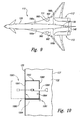
- Figure 9 is a partially schematic plan view of an aircraft 110 having a plurality of airflow control devices in accordance with another embodiment of the invention.
- the aircraft 110 can include a forward pair of airflow control devices 160a and an aft pair of airflow control devices 160b, all of which are mounted to and deployed from the fuselage 120.
- all four airflow control devices 160a-b can be deployed simultaneously.
- one pair of airflow control devices can be deployed separately from the other, for example, to provide a reduced level of drag increase.
- the airflow control devices 160a-b can be positioned relatively close to the center of lift of the aircraft 110 to limit the amount of aircraft pitch-up or pitch-down that results when only one pair of airflow control devices is deployed.
- airflow control devices 160a-b on one side of the fuselage 120 can be deployed without deploying the airflow control devices on the other side of the fuselage 120 to induce a yawing moment.
- the airflow control devices can be mounted to the aircraft wing 111.
- the aircraft 110 can include two airflow control devices 960, each mounted on the wing 111 on opposite sides of the fuselage 120.
- Each airflow control device 960 can be coupled to the fuselage 120 with an airflow duct 962 to pressurize the fuselage 120 in a manner generally similar to that described above with reference to Figures 3A-7 .
- the airflow control devices 960 can be mounted on the wing upper surface.
- the airflow control devices 160 and/or 960 can be coupled to other portions of the aircraft.
- One feature of the embodiments of the airflow control devices described above with reference to Figures 2-10 is that they can include air scoops that move between a stowed position (in which the air scoop has a zero or negligible effect on aircraft drag) and a deployed position (in which the air scoop has a substantial or significant effect on aircraft drag). Accordingly, the air scoops can increase the aircraft rate of descent during normal approach and landing and/or during an emergency descent. This advantage can be particularly beneficial for aircraft with high wing planform areas (such as delta-winged aircraft) but can also be beneficial for aircraft having conventional swept-wing configurations.
- Another feature of the embodiments of the airflow control devices described above with reference to Figures 2-10 is that they can deliver pressurized air to the pressurized portion of the fuselage in addition to or in lieu of increasing aircraft drag, to reduce the time during which the fuselage is exposed to low pressures during a depressurization event.
- An advantage of this arrangement is that the air scoops can provide an additional source of pressurized air during an aircraft depressurization event, and can reduce the time during which passengers and/or cargo in the aircraft are exposed to low atmospheric pressures.
- the same device i.e., the airflow control device
- the airflow control device can provide both the increased descent rate capability and the cabin pressurization capability in a single aircraft system.
- the air scoops can provide pressurized air to the cargo portion and make use of existing floor release panels to pass the pressurized air into the cabin portion.
- the air provided by the air scoop can bypass any aircraft turbomachinery (such as the primary engines and auxiliary power unit) such that the delivery of pressurized air is independent of these turbomachinery devices.
- the air can pass through the cargo portion 122 before entering the cabin portion 121 and accordingly has an opportunity to heat up and diffuse before entering the cabin portion 121.
- Still another advantage of this feature is that the benefits of passing the air through the cargo portion 122 first can be achieved without requiring additional ducting beyond that provided in the aircraft for normal ECS system operation.
- Yet another feature of the embodiments described above is that the air initially entering the cabin portion from the air scoop can bypass the ECS pack 130. Accordingly, air can be introduced into the aircraft after a depressurization event without requiring the ECS pack 130.
- An advantage of this arrangement is that the aircraft can be pressurized even if the depressurization event adversely affects the ECS pack 130.
Landscapes
- Health & Medical Sciences (AREA)
- General Health & Medical Sciences (AREA)
- Pulmonology (AREA)
- Engineering & Computer Science (AREA)
- Aviation & Aerospace Engineering (AREA)
- Fluid-Pressure Circuits (AREA)
- Aerodynamic Tests, Hydrodynamic Tests, Wind Tunnels, And Water Tanks (AREA)
- Control Of Positive-Displacement Air Blowers (AREA)
- Arrangements For Transmission Of Measured Signals (AREA)
- Measurement Of Velocity Or Position Using Acoustic Or Ultrasonic Waves (AREA)
Applications Claiming Priority (2)
| Application Number | Priority Date | Filing Date | Title |
|---|---|---|---|
| US10/044,517 US6634597B2 (en) | 2002-01-11 | 2002-01-11 | Method and apparatus for controlling aircraft airflow |
| EP03075094A EP1327581B2 (de) | 2002-01-11 | 2003-01-10 | Verfahren und Vorrichtung zur Steuerung von Strömungen um Flugzeuge |
Related Parent Applications (1)
| Application Number | Title | Priority Date | Filing Date |
|---|---|---|---|
| EP03075094A Division EP1327581B2 (de) | 2002-01-11 | 2003-01-10 | Verfahren und Vorrichtung zur Steuerung von Strömungen um Flugzeuge |
Publications (2)
| Publication Number | Publication Date |
|---|---|
| EP1894837A2 true EP1894837A2 (de) | 2008-03-05 |
| EP1894837A3 EP1894837A3 (de) | 2016-12-28 |
Family
ID=21932827
Family Applications (2)
| Application Number | Title | Priority Date | Filing Date |
|---|---|---|---|
| EP07076106.9A Withdrawn EP1894837A3 (de) | 2002-01-11 | 2003-01-10 | Verfahren und Vorrichtung zur Steuerung des Luftstroms in einem Flugzeug |
| EP03075094A Expired - Lifetime EP1327581B2 (de) | 2002-01-11 | 2003-01-10 | Verfahren und Vorrichtung zur Steuerung von Strömungen um Flugzeuge |
Family Applications After (1)
| Application Number | Title | Priority Date | Filing Date |
|---|---|---|---|
| EP03075094A Expired - Lifetime EP1327581B2 (de) | 2002-01-11 | 2003-01-10 | Verfahren und Vorrichtung zur Steuerung von Strömungen um Flugzeuge |
Country Status (4)
| Country | Link |
|---|---|
| US (1) | US6634597B2 (de) |
| EP (2) | EP1894837A3 (de) |
| AT (1) | ATE398571T1 (de) |
| DE (1) | DE60321608D1 (de) |
Cited By (1)
| Publication number | Priority date | Publication date | Assignee | Title |
|---|---|---|---|---|
| CN109204848A (zh) * | 2018-07-24 | 2019-01-15 | 中国商用飞机有限责任公司 | 伸缩式辅助进气装置 |
Families Citing this family (41)
| Publication number | Priority date | Publication date | Assignee | Title |
|---|---|---|---|---|
| US7014144B2 (en) * | 2003-07-22 | 2006-03-21 | Honeywell International, Inc. | Dual action inlet door and method for use thereof |
| US7150431B2 (en) * | 2004-01-14 | 2006-12-19 | Mjd Innovations, L.L.C. | Electrical generator fluid-flow-coolant filtration |
| US7159821B2 (en) * | 2004-04-02 | 2007-01-09 | The Boeing Company | Integrated transport system for overhead stowage |
| US7159818B2 (en) * | 2004-10-05 | 2007-01-09 | Northrop Grumman Ship Systems, Inc. | Multi-spectral air inlet shield and associated inlet structure |
| DE102004061372B4 (de) * | 2004-12-21 | 2011-05-26 | Airbus Operations Gmbh | Anordnung und Verfahren zur Abluftwärmenutzung zum Beheizen des Bilgebereiches von Flugzeugen |
| US7462098B2 (en) * | 2005-03-16 | 2008-12-09 | Honeywell International, Inc. | Cabin pressure control system and method that accommodates aircraft take-off with and without a cabin pressurization source |
| DE102005053696B4 (de) * | 2005-11-10 | 2009-05-14 | Airbus Deutschland Gmbh | Notfall-Staulufteinlassklappe eines Flugzeuges |
| US7600714B2 (en) * | 2006-04-20 | 2009-10-13 | Honeywell International Inc. | Diffusing air inlet door assembly |
| FR2915733B1 (fr) * | 2007-05-04 | 2009-06-05 | Airbus France Sas | Dispositif de sortie d'air mobile pour un aeronef |
| FR2928465B1 (fr) * | 2008-03-10 | 2011-09-23 | Airbus France | Procede et dispositif de controle automatique d'une descente d'urgence d'un aeronef |
| US8132758B2 (en) * | 2008-03-12 | 2012-03-13 | Hamilton Sundstrand Corporation | Environmental control system pack pallets |
| DE102008030399B4 (de) * | 2008-06-26 | 2019-03-21 | Airbus Operations Gmbh | Luftkanal zur Umgebungsluftzufuhr in einem Flugzeug |
| DE102008056417B4 (de) | 2008-11-07 | 2010-11-11 | Airbus Deutschland Gmbh | Verfahren und System zur Notbelüftung einer Flugzeugkabine |
| DE102008058451B4 (de) * | 2008-11-21 | 2010-11-18 | Airbus Deutschland Gmbh | Verfahren und System zur Notbelüftung einer Flugzeugkabine im Fall eines Lecks im Bereich eines Luftmischers |
| US8245976B2 (en) * | 2009-01-19 | 2012-08-21 | The Boeing Company | Door assembly for laminar flow control system |
| US8128037B2 (en) * | 2009-01-19 | 2012-03-06 | The Boeing Company | Apparatus and method for passive purging of micro-perforated aerodynamic surfaces |
| US8322981B2 (en) * | 2009-03-02 | 2012-12-04 | Hamilton Sundstrand Corporation | Aircraft fluid diversion inlet louver |
| DE102010005902B4 (de) * | 2010-01-27 | 2017-09-14 | Airbus Operations Gmbh | Flugzeug mit mindestens einem druckbeaufschlagten Rumpfbereich und mindestens einem nicht druckbeaufschlagten Bereich sowie Verfahren zum Belüften eines nicht druckbeaufschlagten Bereichs eines Flugzeugs |
| US8938973B2 (en) * | 2010-02-11 | 2015-01-27 | Pratt & Whitney Canada Corp. | Air contamination detection in an aircraft air system |
| US9090326B2 (en) * | 2010-10-13 | 2015-07-28 | The Boeing Company | Active flow control on a vertical stabilizer and rudder |
| US20120096772A1 (en) * | 2010-10-25 | 2012-04-26 | Hamilton Sundstrand Corporation | Door System |
| US9102392B2 (en) * | 2010-12-15 | 2015-08-11 | The Boeing Company | Method and apparatus for air flow control in an aircraft sidewall volume |
| DE102011110068B4 (de) * | 2011-08-12 | 2014-01-09 | Eads Deutschland Gmbh | Vorrichtung zum Betreiben einer Lithium-Luft-Batterie eines Luftfahrzeugs und zur Aufbereitung von Kabinenluft des Luftfahrzeugs |
| US9475584B2 (en) | 2011-09-02 | 2016-10-25 | Honeywell International Inc. | Cabin pressure control system thrust recovery outflow valve and method that enable ram air recovery |
| US9067680B2 (en) * | 2011-09-29 | 2015-06-30 | The Boeing Company | Aircraft outflow valve |
| FR2990189B1 (fr) * | 2012-05-02 | 2015-01-02 | Airbus Operations Sas | Porte de surpression pour aeronef. |
| EP2740665B1 (de) | 2012-12-10 | 2017-02-08 | Airbus Operations GmbH | Verbessertes verfahren und system für notbelüftung und -bedruckung einer flugzeugkabine |
| US9487288B2 (en) | 2013-06-04 | 2016-11-08 | The Boeing Company | Apparatus and methods for extending hybrid laminar flow control |
| US9815564B2 (en) * | 2013-12-04 | 2017-11-14 | The Boeing Company | Non-propulsive utility power (NPUP) generation system for providing full-time secondary power during operation of an aircraft |
| EP2889466A1 (de) * | 2013-12-31 | 2015-07-01 | Rolls-Royce Deutschland Ltd & Co KG | Strömungsführungssystem, Turbomaschine mit einem Strömungsführungssystem und Verfahren zur Herstellung eines Strömungsführungssystems |
| US10059430B2 (en) * | 2014-06-25 | 2018-08-28 | Gulfstream Aerospace Corporation | Aircraft air scoop systems with passive pneumatic actuators |
| US10472071B2 (en) * | 2014-07-09 | 2019-11-12 | United Technologies Corporation | Hybrid compressor bleed air for aircraft use |
| US9783306B2 (en) | 2015-10-13 | 2017-10-10 | Honeywell International Inc. | Bi-fold thrust recovery outflow valve with a ram air flap |
| US10773817B1 (en) * | 2018-03-08 | 2020-09-15 | Northrop Grumman Systems Corporation | Bi-directional flow ram air system for an aircraft |
| US20190276158A1 (en) * | 2018-03-08 | 2019-09-12 | Bell Helicopter Textron Inc. | Active cooling system |
| US11703890B2 (en) * | 2018-10-30 | 2023-07-18 | Hamilton Sundstrand Corporation | Determining and controlling a weight flow in an environmental control system |
| US12179934B2 (en) * | 2019-05-06 | 2024-12-31 | The Boeing Company | Method and apparatus for auxiliary power unit installation |
| US11713126B2 (en) | 2019-08-12 | 2023-08-01 | The Boeing Company | Aircraft air conditioning pack assembly and method of assembling |
| US11454572B2 (en) * | 2020-06-04 | 2022-09-27 | Saudi Arabian Oil Company | Method of placing gas sensors on drones to benefit from thrust air flow via placement and scoops |
| US11603214B2 (en) * | 2020-06-04 | 2023-03-14 | Saudi Arabian Oil Company | Calibration methods for gas sensors mounted in-stream of drone propeller air flow |
| US11565794B2 (en) * | 2020-06-04 | 2023-01-31 | Saudi Arabian Oil Company | Gas sensing for fixed wing drones using scoops |
Family Cites Families (10)
| Publication number | Priority date | Publication date | Assignee | Title |
|---|---|---|---|---|
| US2122447A (en) * | 1933-03-29 | 1938-07-05 | Sperry Gyroscope Co Inc | Noise reducing means for cabin aircraft |
| US3101918A (en) * | 1961-05-31 | 1963-08-27 | Boeing Co | Emergency ram air cabin pressurization system |
| US3129910A (en) * | 1962-12-18 | 1964-04-21 | Robert D Smith | Aircraft air scoop for inflatable air blanket safety equipment |
| DE2029477A1 (de) † | 1970-06-15 | 1971-12-23 | Messerschmitt-Bölkow-Blohm GmbH, 8000 München | Flugzeug mit Bremsklappen sowie einer vom Fahrtwind betriebenen Notturbine |
| US4314341A (en) | 1980-01-24 | 1982-02-02 | Sperry Corporation | Aircraft automatic pilot with automatic emergency descent control apparatus |
| US4418879A (en) * | 1980-12-29 | 1983-12-06 | The Boeing Company | Scoop and inlet for auxiliary power units and method |
| US4394861A (en) * | 1981-05-11 | 1983-07-26 | Sciortino Lawrence A | Outside air breathing supply system |
| US4979699A (en) * | 1989-05-26 | 1990-12-25 | Grumman Aerospace Corporation | Flight control augmentation inlet device |
| US4979669A (en) † | 1989-07-07 | 1990-12-25 | Michael Kerton | Self-closing box |
| GB2261613A (en) * | 1991-11-22 | 1993-05-26 | Ford Motor Co | Operation of an internal combustion engine |
-
2002
- 2002-01-11 US US10/044,517 patent/US6634597B2/en not_active Expired - Fee Related
-
2003
- 2003-01-10 EP EP07076106.9A patent/EP1894837A3/de not_active Withdrawn
- 2003-01-10 DE DE60321608T patent/DE60321608D1/de not_active Expired - Lifetime
- 2003-01-10 AT AT03075094T patent/ATE398571T1/de not_active IP Right Cessation
- 2003-01-10 EP EP03075094A patent/EP1327581B2/de not_active Expired - Lifetime
Cited By (2)
| Publication number | Priority date | Publication date | Assignee | Title |
|---|---|---|---|---|
| CN109204848A (zh) * | 2018-07-24 | 2019-01-15 | 中国商用飞机有限责任公司 | 伸缩式辅助进气装置 |
| CN109204848B (zh) * | 2018-07-24 | 2022-03-22 | 中国商用飞机有限责任公司 | 伸缩式辅助进气装置 |
Also Published As
| Publication number | Publication date |
|---|---|
| US20030132344A1 (en) | 2003-07-17 |
| EP1327581A3 (de) | 2005-09-14 |
| EP1894837A3 (de) | 2016-12-28 |
| EP1327581A2 (de) | 2003-07-16 |
| EP1327581B8 (de) | 2008-08-13 |
| DE60321608D1 (de) | 2008-07-31 |
| EP1327581B2 (de) | 2011-12-28 |
| EP1327581B1 (de) | 2008-06-18 |
| US6634597B2 (en) | 2003-10-21 |
| ATE398571T1 (de) | 2008-07-15 |
Similar Documents
| Publication | Publication Date | Title |
|---|---|---|
| EP1327581B1 (de) | Verfahren und Vorrichtung zur Steuerung von Strömungen um Flugzeuge | |
| Howard | Quiet Clean Short-haul Experimental Engine (QCSEE) preliminary under the wing flight propulsion system analysis report | |
| McCracken | Quiet short-haul research aircraft familiarization document | |
| US8398022B2 (en) | Wide body aircraft architecture | |
| US20190375505A1 (en) | Detachable Pilotable Capsules and Aircrafts Including Detachable Pilotable Capsules | |
| US9248912B2 (en) | Method and system for emergency ventilation of an aircraft cabin | |
| WO2005065071A2 (en) | Supersonic aircraft | |
| RU2349505C1 (ru) | Способ создания подъемной силы самолета (варианты), способ полета самолета, безаэродромный всепогодный самолет "максинио" вертикального взлета и посадки (варианты), способ взлета и способ посадки, способ и система управления самолетом в полете, фюзеляж, крыло (варианты), реверс тяги и способ его работы, система шасси, система газоразделения и газораспределения его | |
| EP3478578A1 (de) | Luftfahrzeug mit kurzem start und landung | |
| EP0596131B1 (de) | Flugobjekt | |
| Vijgen et al. | Conceptual Integration Studies of Localized Active Flow Control on the Wing of a Commercial Aircraft | |
| US6382562B1 (en) | AFT egress and control device for an aircraft | |
| Laten et al. | NATO AVT-350 task group: platform integration to assess prospects of active flow control on a next-gen tailless UAS–Part II TO/L regime | |
| Norton | STOL progenitors: the technology path to a large STOL transport and the C-17A | |
| Edi | Investigation of the application of hybrid laminar flow control and variable camber wing design for regional aircraft | |
| RU2297951C1 (ru) | Самолет с плоским фюзеляжем | |
| RU2661005C2 (ru) | Способ регулирования подъемной силы летательного аппарата и летательный аппарат | |
| LINDERMAN et al. | Test and evaluation of a fighter aircraft in-flight thrust reverser | |
| Bready | Design and Development of the Lockheed C-5A Environmental Control System | |
| Zabinsky et al. | V/STOL lift fan commercial short haul transports: Continuing conceptual design study | |
| Christofferson et al. | Design Team I | |
| Cavage | Conceptual design study of improved 1985 remote lift-fan V/STOL commercial transports | |
| JP2948325B2 (ja) | 航空機 | |
| Everett | Trace: Tennessee Research and Creative Exchange | |
| Everett | MedJet |
Legal Events
| Date | Code | Title | Description |
|---|---|---|---|
| PUAI | Public reference made under article 153(3) epc to a published international application that has entered the european phase |
Free format text: ORIGINAL CODE: 0009012 |
|
| AC | Divisional application: reference to earlier application |
Ref document number: 1327581 Country of ref document: EP Kind code of ref document: P |
|
| AK | Designated contracting states |
Kind code of ref document: A2 Designated state(s): AT BE BG CH CY CZ DE DK EE ES FI FR GB GR HU IE IT LI LU MC NL PT SE SI SK TR |
|
| PUAL | Search report despatched |
Free format text: ORIGINAL CODE: 0009013 |
|
| AK | Designated contracting states |
Kind code of ref document: A3 Designated state(s): AT BE BG CH CY CZ DE DK EE ES FI FR GB GR HU IE IT LI LU MC NL PT SE SI SK TR |
|
| RIC1 | Information provided on ipc code assigned before grant |
Ipc: B64D 13/00 20060101ALI20161124BHEP Ipc: B64D 13/02 20060101ALI20161124BHEP Ipc: B64C 9/32 20060101AFI20161124BHEP |
|
| 17P | Request for examination filed |
Effective date: 20170628 |
|
| AKX | Designation fees paid |
Designated state(s): AT BE BG CH CY CZ DE DK EE ES FI FR GB GR HU IE IT LI LU MC NL PT SE SI SK TR |
|
| STAA | Information on the status of an ep patent application or granted ep patent |
Free format text: STATUS: THE APPLICATION IS DEEMED TO BE WITHDRAWN |
|
| 18D | Application deemed to be withdrawn |
Effective date: 20190801 |