EP1895030A2 - Verfahren und Anordnung zur Herstellung eines Rohres - Google Patents
Verfahren und Anordnung zur Herstellung eines Rohres Download PDFInfo
- Publication number
- EP1895030A2 EP1895030A2 EP07114918A EP07114918A EP1895030A2 EP 1895030 A2 EP1895030 A2 EP 1895030A2 EP 07114918 A EP07114918 A EP 07114918A EP 07114918 A EP07114918 A EP 07114918A EP 1895030 A2 EP1895030 A2 EP 1895030A2
- Authority
- EP
- European Patent Office
- Prior art keywords
- tube
- melt
- temperature
- meniscus
- crucible
- Prior art date
- Legal status (The legal status is an assumption and is not a legal conclusion. Google has not performed a legal analysis and makes no representation as to the accuracy of the status listed.)
- Granted
Links
- 238000000034 method Methods 0.000 title claims abstract description 24
- 238000004519 manufacturing process Methods 0.000 title claims description 8
- 239000000155 melt Substances 0.000 claims abstract description 50
- 230000001105 regulatory effect Effects 0.000 claims abstract description 8
- 238000010438 heat treatment Methods 0.000 claims description 42
- 230000005499 meniscus Effects 0.000 claims description 39
- 239000000463 material Substances 0.000 claims description 20
- XUIMIQQOPSSXEZ-UHFFFAOYSA-N Silicon Chemical compound [Si] XUIMIQQOPSSXEZ-UHFFFAOYSA-N 0.000 claims description 15
- 230000006698 induction Effects 0.000 claims description 15
- 229910052710 silicon Inorganic materials 0.000 claims description 15
- 239000010703 silicon Substances 0.000 claims description 15
- 238000002844 melting Methods 0.000 claims description 10
- 230000008018 melting Effects 0.000 claims description 10
- 238000012545 processing Methods 0.000 claims description 5
- OKTJSMMVPCPJKN-UHFFFAOYSA-N Carbon Chemical compound [C] OKTJSMMVPCPJKN-UHFFFAOYSA-N 0.000 claims description 4
- 229910002804 graphite Inorganic materials 0.000 claims description 4
- 239000010439 graphite Substances 0.000 claims description 4
- 230000003287 optical effect Effects 0.000 claims description 4
- 230000001276 controlling effect Effects 0.000 claims description 3
- 229910000831 Steel Inorganic materials 0.000 claims description 2
- 239000010959 steel Substances 0.000 claims description 2
- XLYOFNOQVPJJNP-UHFFFAOYSA-N water Substances O XLYOFNOQVPJJNP-UHFFFAOYSA-N 0.000 claims description 2
- 238000005231 Edge Defined Film Fed Growth Methods 0.000 abstract description 8
- 239000013078 crystal Substances 0.000 description 6
- 230000008569 process Effects 0.000 description 6
- 230000033228 biological regulation Effects 0.000 description 5
- 238000009826 distribution Methods 0.000 description 5
- 238000009413 insulation Methods 0.000 description 5
- 238000005259 measurement Methods 0.000 description 5
- 230000007704 transition Effects 0.000 description 5
- 235000012431 wafers Nutrition 0.000 description 5
- 238000001816 cooling Methods 0.000 description 3
- 238000011161 development Methods 0.000 description 3
- 238000010586 diagram Methods 0.000 description 3
- 239000008187 granular material Substances 0.000 description 3
- 229910000859 α-Fe Inorganic materials 0.000 description 3
- 244000089486 Phragmites australis subsp australis Species 0.000 description 2
- 238000007664 blowing Methods 0.000 description 2
- 230000008859 change Effects 0.000 description 2
- 239000011521 glass Substances 0.000 description 2
- 239000007791 liquid phase Substances 0.000 description 2
- 239000007790 solid phase Substances 0.000 description 2
- 238000005496 tempering Methods 0.000 description 2
- 230000009471 action Effects 0.000 description 1
- 238000009529 body temperature measurement Methods 0.000 description 1
- 229910052799 carbon Inorganic materials 0.000 description 1
- 238000005253 cladding Methods 0.000 description 1
- 238000013461 design Methods 0.000 description 1
- 230000005672 electromagnetic field Effects 0.000 description 1
- 239000007788 liquid Substances 0.000 description 1
- 239000002184 metal Substances 0.000 description 1
- 239000012071 phase Substances 0.000 description 1
- 229910021420 polycrystalline silicon Inorganic materials 0.000 description 1
- 230000005855 radiation Effects 0.000 description 1
- 239000011856 silicon-based particle Substances 0.000 description 1
- 238000009827 uniform distribution Methods 0.000 description 1
- 238000005303 weighing Methods 0.000 description 1
Images


Classifications
-
- C—CHEMISTRY; METALLURGY
- C30—CRYSTAL GROWTH
- C30B—SINGLE-CRYSTAL GROWTH; UNIDIRECTIONAL SOLIDIFICATION OF EUTECTIC MATERIAL OR UNIDIRECTIONAL DEMIXING OF EUTECTOID MATERIAL; REFINING BY ZONE-MELTING OF MATERIAL; PRODUCTION OF A HOMOGENEOUS POLYCRYSTALLINE MATERIAL WITH DEFINED STRUCTURE; SINGLE CRYSTALS OR HOMOGENEOUS POLYCRYSTALLINE MATERIAL WITH DEFINED STRUCTURE; AFTER-TREATMENT OF SINGLE CRYSTALS OR A HOMOGENEOUS POLYCRYSTALLINE MATERIAL WITH DEFINED STRUCTURE; APPARATUS THEREFOR
- C30B15/00—Single-crystal growth by pulling from a melt, e.g. Czochralski method
- C30B15/14—Heating of the melt or the crystallised materials
-
- C—CHEMISTRY; METALLURGY
- C30—CRYSTAL GROWTH
- C30B—SINGLE-CRYSTAL GROWTH; UNIDIRECTIONAL SOLIDIFICATION OF EUTECTIC MATERIAL OR UNIDIRECTIONAL DEMIXING OF EUTECTOID MATERIAL; REFINING BY ZONE-MELTING OF MATERIAL; PRODUCTION OF A HOMOGENEOUS POLYCRYSTALLINE MATERIAL WITH DEFINED STRUCTURE; SINGLE CRYSTALS OR HOMOGENEOUS POLYCRYSTALLINE MATERIAL WITH DEFINED STRUCTURE; AFTER-TREATMENT OF SINGLE CRYSTALS OR A HOMOGENEOUS POLYCRYSTALLINE MATERIAL WITH DEFINED STRUCTURE; APPARATUS THEREFOR
- C30B15/00—Single-crystal growth by pulling from a melt, e.g. Czochralski method
- C30B15/20—Controlling or regulating
- C30B15/22—Stabilisation or shape controlling of the molten zone near the pulled crystal; Controlling the section of the crystal
-
- C—CHEMISTRY; METALLURGY
- C30—CRYSTAL GROWTH
- C30B—SINGLE-CRYSTAL GROWTH; UNIDIRECTIONAL SOLIDIFICATION OF EUTECTIC MATERIAL OR UNIDIRECTIONAL DEMIXING OF EUTECTOID MATERIAL; REFINING BY ZONE-MELTING OF MATERIAL; PRODUCTION OF A HOMOGENEOUS POLYCRYSTALLINE MATERIAL WITH DEFINED STRUCTURE; SINGLE CRYSTALS OR HOMOGENEOUS POLYCRYSTALLINE MATERIAL WITH DEFINED STRUCTURE; AFTER-TREATMENT OF SINGLE CRYSTALS OR A HOMOGENEOUS POLYCRYSTALLINE MATERIAL WITH DEFINED STRUCTURE; APPARATUS THEREFOR
- C30B15/00—Single-crystal growth by pulling from a melt, e.g. Czochralski method
- C30B15/34—Edge-defined film-fed crystal-growth using dies or slits
-
- C—CHEMISTRY; METALLURGY
- C30—CRYSTAL GROWTH
- C30B—SINGLE-CRYSTAL GROWTH; UNIDIRECTIONAL SOLIDIFICATION OF EUTECTIC MATERIAL OR UNIDIRECTIONAL DEMIXING OF EUTECTOID MATERIAL; REFINING BY ZONE-MELTING OF MATERIAL; PRODUCTION OF A HOMOGENEOUS POLYCRYSTALLINE MATERIAL WITH DEFINED STRUCTURE; SINGLE CRYSTALS OR HOMOGENEOUS POLYCRYSTALLINE MATERIAL WITH DEFINED STRUCTURE; AFTER-TREATMENT OF SINGLE CRYSTALS OR A HOMOGENEOUS POLYCRYSTALLINE MATERIAL WITH DEFINED STRUCTURE; APPARATUS THEREFOR
- C30B29/00—Single crystals or homogeneous polycrystalline material with defined structure characterised by the material or by their shape
- C30B29/02—Elements
- C30B29/06—Silicon
-
- C—CHEMISTRY; METALLURGY
- C30—CRYSTAL GROWTH
- C30B—SINGLE-CRYSTAL GROWTH; UNIDIRECTIONAL SOLIDIFICATION OF EUTECTIC MATERIAL OR UNIDIRECTIONAL DEMIXING OF EUTECTOID MATERIAL; REFINING BY ZONE-MELTING OF MATERIAL; PRODUCTION OF A HOMOGENEOUS POLYCRYSTALLINE MATERIAL WITH DEFINED STRUCTURE; SINGLE CRYSTALS OR HOMOGENEOUS POLYCRYSTALLINE MATERIAL WITH DEFINED STRUCTURE; AFTER-TREATMENT OF SINGLE CRYSTALS OR A HOMOGENEOUS POLYCRYSTALLINE MATERIAL WITH DEFINED STRUCTURE; APPARATUS THEREFOR
- C30B29/00—Single crystals or homogeneous polycrystalline material with defined structure characterised by the material or by their shape
- C30B29/60—Single crystals or homogeneous polycrystalline material with defined structure characterised by the material or by their shape characterised by shape
- C30B29/66—Crystals of complex geometrical shape, e.g. tubes, cylinders
-
- Y—GENERAL TAGGING OF NEW TECHNOLOGICAL DEVELOPMENTS; GENERAL TAGGING OF CROSS-SECTIONAL TECHNOLOGIES SPANNING OVER SEVERAL SECTIONS OF THE IPC; TECHNICAL SUBJECTS COVERED BY FORMER USPC CROSS-REFERENCE ART COLLECTIONS [XRACs] AND DIGESTS
- Y10—TECHNICAL SUBJECTS COVERED BY FORMER USPC
- Y10T—TECHNICAL SUBJECTS COVERED BY FORMER US CLASSIFICATION
- Y10T117/00—Single-crystal, oriented-crystal, and epitaxy growth processes; non-coating apparatus therefor
- Y10T117/10—Apparatus
- Y10T117/1024—Apparatus for crystallization from liquid or supercritical state
- Y10T117/1032—Seed pulling
- Y10T117/1036—Seed pulling including solid member shaping means other than seed or product [e.g., EDFG die]
- Y10T117/104—Means for forming a hollow structure [e.g., tube, polygon]
Definitions
- the invention relates to a method for producing a crystalline tube from a material such as silicon by drawing the tube from a melt, which is produced by melting the material supplied to a crucible by means of a heater, wherein the melt has a capillary gap which predetermines the geometry of the tube and passes through this with a meniscus of a height h, which merges into a geometry corresponding to the tube germ or lower edge region of a drawn portion of the tube to be produced.
- the invention relates to an arrangement for drawing a tube from a melt comprising a crucible with a predetermining the geometry of the tube penetrated by the melt capillary gap, which is surmounted by the melt with a meniscus height h, and at least one of the crucible associated heating and pulling the pipe pulling device.
- a corresponding method is also known as EFG (Edge-Defined-Film-Fed-Growth) method, are drawn with the polygonal, in particular 8-cornered tubes from a melt such as silicon melt. Usual edge distances are 125 mm. Slices are then cut out of the corresponding sides by means of a laser, which have edge lengths of 100 ⁇ 100 mm or larger.
- EFG Edge-Defined-Film-Fed-Growth
- the DE-T-691 24 441 has a system for controlling a plant for growing crystals.
- the actual weight of the growing crystal body is used as a controlled variable to supply material to the required extent to the melt.
- the US-A-4,544,528 describes a device for pulling pipes according to the EFG method.
- the device is characterized in that heat shields are provided in the region of the transition of melt and solidified tube. Furthermore, internal and external afterheating devices are installed in the region of the solidified tube.
- the DE-A-23 25 104 refers to crystal pulling methods for pipes or threads. In order to keep the outer diameter of the pipes within prescribed limits, the height of the meniscus is measured and the temperature is controlled as a function of its height.
- a melt receiving crucible in which a former is arranged with channels, which are penetrated by the melt.
- the channels terminate at the top of the former at a seed crystal.
- a heating device for melting a heating device is provided, which consists of U-shaped blades, which are bent according to the shape of the crucible.
- the lamellae are arranged in sections to achieve radial isothermal states.
- the present invention is based on the object, a method and an arrangement of the type mentioned in such a way that pipes can be produced which have a desired constant wall thickness, so show a narrow thickness distribution.
- the average use of the material from which the Tube is pulled minimized.
- the object is essentially achieved by a method of the type mentioned above in that the temperature in adjoining areas of the melt is set independently by regulation.
- the temperature of the melt in the individual regions is regulated as a function of the height h of the meniscus of the melt flowing out of the respective region into the capillary gap and / or as a function of the wall thickness t of the tube section drawn out of the region.
- a control of the temperature of the melt can be carried out such that in the meniscus, in the transition region between the melt and the solidified tube section, a temperature prevails which corresponds to the melting point of the material.
- the temperature at silicon as the material is 1412 ° C ⁇ 2 ° C, the temperature being kept constant with an accuracy of 0.1 ° C to 2 ° C.
- the height h of the meniscus or the thickness t of the tube in the respective area or above this can be used as a parameter, the height h of the meniscus or the thickness t of the tube in the respective area or above this as a controlled variable, depending on the measured values, the temperatures in the Set area.
- the drawing speed can be changed accordingly, whereby basically both the pulling speed and the temperature are regulated.
- the measurement of the thickness of the tube is preferably carried out in the upper edge region of the pulling device.
- the individual regulation of the temperatures in the individual areas is effected in particular by assigning to each area a separate heating element, such as, preferably, a resistance heating element, which are preferably interconnected in a star connection.
- a separate heating element such as, preferably, a resistance heating element, which are preferably interconnected in a star connection.
- each ferritic element which is assigned to each area, z. B. be adjusted radially by means of a motor.
- this should be set to a value between 7 mm / min to 24 mm / min with a tolerance of 1 mm / min, with the drawing speed preferably being between 12 mm / min and 15 mm / min.
- each side of the polygon has an area assigned to it, ie each side is individually regulated in terms of temperature.
- eight heating elements or eight independently adjustable ferritic elements are provided when using an induction heater.
- twelve heating elements or ferritic elements are accordingly present in order to carry out the temperature control can.
- a resistance heating element it preferably consists of graphite.
- Metallic resistance heating elements with which the required temperatures for setting the melting temperatures can be generated, also come into question.
- the temperature of the melt is often not measured directly by design. Rather, the temperature of the wall of the molten bath z. B. determined with a pyrometer. However, there is also the possibility z. B. by means of a thermocouple directly to detect the melting temperature.
- an optical sensor In order to measure the height h of the meniscus, ie the transition between solid and liquid phase, an optical sensor is used.
- a CCD camera with image processing is provided.
- viewing windows may be present in the cladding of the molten bath in order to determine the height h of the meniscus in each region.
- the wall thickness of the pulled out of the range pipe section can interferometric, such. B. be measured with an IR interferometer.
- the measuring equipment for the wall thickness measurement or the height of the meniscus are connected to a controller, which then controls the heating for each Beriech.
- the speed can also be specified by the controller.
- the material to be melted is introduced into the crucible so as to supply to each region the amount corresponding to the amount withdrawn from the melt.
- the tube and the material supply are each connected to a load cell in order to make the required control.
- the drawn tube is silicon
- silicon wafers of desired sizes in particular with edge lengths of up to 156 mm (6 inches), wall thicknesses below 350 ⁇ m, in particular below 290 ⁇ m, can consequently be produced, so that a high filling factor, a high short-circuit current density and a high open-circuit voltage of a solar cell made of polycrystalline silicon produced from the wafer, values which are not available at least on an industrial scale with the inventively achievable reproducibility according to the prior art.
- the method of the type mentioned above is characterized in particular in that the temperature of the melt - preferably in mutually adjacent areas independently of each other - is controlled so that the temperature of the meniscus is maintained over the entire length of the gap to a constant or nearly constant value and / or the temperature of contiguous regions of the crucible is regulated independently of one another as a function of the height h of the meniscus of the melt flowing out of the region into the capillary gap and / or as a function of the wall thickness t of the tube section drawn from the region; and / or the pulling rate of the pipe section drawn from the melt is regulated as a function of the height h of the meniscus and / or the wall thickness t of the pipe section.
- An arrangement of the type mentioned above is characterized in that individual, in particular adjacent areas of the crucible or the melt are independently temperature controlled by means of one or more heaters. It is provided in particular that each area is assigned a resistance heating element, wherein the resistance heating elements can be connected to each other in a star connection.
- each area is associated with a magnetic field of the induction heating influencing ferritic element, which is independent are adjustable from each other.
- each ferritic element is adjustable by means of a motor.
- the respective area is assigned a first measuring device measuring the height h of the meniscus, which is in particular a CCD camera with connected image processing.
- the sensors for measuring the wall thickness t should be arranged at a sufficient distance from the melt, preferably in the upper edge region of the drawing system or its housing.
- each region is assigned a wall thickness t of the second tube drawn from the region of the tube, which is in particular an interferometer such as an IR interferometer.
- the first and / or second measuring device and the heaters which can be temperature-controlled are connected via a regulator, which should also be connected to the pulling device.
- a tube produced by the method according to the invention is characterized in particular in that the tube has a circumference U with U ⁇ 100 cm, in particular U ⁇ 150 cm, a length L with L ⁇ 550 cm, in particular L ⁇ 600 cm, and a wall thickness t of 100 ⁇ m ⁇ t ⁇ 500 ⁇ m.
- the tube has a dodecagonal geometry.
- Preferred wall thicknesses of the tube are between 250 ⁇ m and 350 ⁇ m with a thickness tolerance between 20% and 30% or between 100 ⁇ m and 240 ⁇ m with a thickness tolerance between 8% and 12%.
- the metallic housing has, on the head side, an opening corresponding to the geometry of the pipe for the passage of the pipe.
- the resistance heating elements should preferably consist of graphite.
- the sensors for wall thickness measurement are preferably the sensors for wall thickness measurement.
- thermocouples For temperature measurement temperature sensors such as pyrometers or thermocouples are provided, wherein the bottom wall of the crucible is measured by means of the pyrometer, so as to be able to draw conclusions about the melting temperature itself.
- the crucible has an annular geometry, wherein the outer diameter is 5% to 15% larger than the largest diagonal of the tube.
- the capillary gap is through a plurality of small holes or slots with the crucible, d. H. connected in this existing melt. If the gap has a polygon geometry, each side of the polygon is assigned to one of the regions which can be temperature-controlled independently of one another.
- a feeder passes through the bottom of the assembly to then distribute the material evenly over the individual regions of the crucible via a diverter.
- the tube drawn out of the melt is surrounded by insulation elements in order to allow targeted cooling.
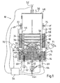
- the arrangement 10 has, as shown in FIG. 1, a housing 12 to be designated as a recipient, which accommodates a bottom insulation 14 in which an annular crucible 16 is arranged.
- material 20 introduced via a feed device 18 is melted, specifically in the embodiment of FIGS. 1 and 2 by means of resistance heating elements 22, 24, 26, 28, via which contiguous regions of the crucible 16 can be heated independently of one another.
- a corresponding division is indicated in FIG. 5 and designated by the reference numerals 17, 19, 21, 23, 25, 27, 29, 31.
- the material that is supplied to the crucible 16 may have a spherical, polygonal or dusty morphology and is introduced via an opening 30 passing through the bottom of the housing 12 and the bottom insulation 14 by means of a blowing device 32, wherein a deflection over a material side has a conical geometry having element 34 which resembles the geometry of a screen, so that the basically granular material along the surface 36 of a cone element in the direction of the crucible 16, ie the ring-shaped receptacle 40 are guided. In this case, a uniform distribution of the granules over the entire circumference of the annular receptacle 40 takes place.
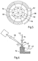
- a capillary action-generating gap 42 which is connected to the silicon melt 41 via slots or bores, runs as shown in FIG. 6, so that the melt 41 flows into the gap 42 and, owing to the capillary action, flows out of the head end, ie emerges at the top and forms a meniscus 44.
- the meniscus 44 solidifies in its upper tip region when pulling a tube 46, so that the tube 46 or the solidified portions are lifted by means of a pulling device 48 in the direction of the arrow 50 accordingly.
- the pulling device 48 is connected to a weighing cell 52, the measured values of which are fed to a regulator 54.
- the blowing device 32 is supplied with the material to be melted from a template 33 via a metering device 35 (FIG. 4).
- the metering device 35 is connected to the regulator 54 via a load cell 37 in order to supply, via the injector 32, to the crucible 16 precisely the amount of material to be melted, which is melted, i. the capillary gap 42 is withdrawn. This amount is determined by means of the load cell 52.
- the pulling device 48 comprises a seed holder 49 which, at the beginning of the drawing process, has a nucleus corresponding to the geometry of the tube to be drawn, which is contacted with the meniscus 44.
- the tube 46 is surrounded above the crucible by an insulation 58 or radiation shields 56 in order to be able to control the cooling of the tube 46 in a controlled manner.
- the melt in the Melting crucible 16 in the adjacent areas 17, 19, 21, 23, 25, 27, 29, 31 is individually tempered, wherein in a tube of polygonal geometry each area corresponds to one side of the polygon.
- the tube has a sectional circle geometry, so the individually tempered areas are tuned to a width of the tube in which are cut out of the tube plates to z. B. to be used as a wafer for solar cells to be produced.
- the temperature of the melting point of the material 20 must prevail in the meniscus 44, specifically in the transition region between the solid phase and the liquid phase, ie the temperature of 1412 ° C. for silicon, which also has a constancy must be less than 2 ° C, in particular in the range between 0.1 ° C and 2 ° C.
- the temperature of the meniscus 44 is not determined directly, but in the embodiment of FIG. 1, the temperature of the bottom of the crucible 16 by means of pyrometer 60, 61, the resistance heating 22, 24, 26, 28 push through.
- the temperature control takes place by means of the regulator 54, which is connected via controllable current connections 62, 64, 66, 68 with the resistance heaters 22, 24, 26, 28.
- the regulator 54 is supplied with the measured heights h of the meniscus 44 in the individual regions 17, 19, 21, 23, 25, 27, 29, 31, on the basis of which the temperature in the regions 17, 19, 21, 23, 25 , 27, 29, 31.
- the heights h are measured with optical sensors 70, 71.
- a CCD camera with downstream image processing is used as the sensor.
- interferometers 72, 74 are provided at the upper edge of the housing 12, wherein an interferometer 72, 74 is assigned to a respective region 17, 19, 21, 23, 25, 27, 29, 31, as well the sensors 70, 71 for measuring the height h of the meniscus 44.
- the tube 46 a 12eckgeometrie on, each of the 12 pages is associated with an optical sensor 70 and 71 and an interferometer 72 and 74, respectively.
- FIG. 5 in an octagonal tube 46, eight regions 17, 19, 21, 23, 25, 27, 29, 31 can be regulated, which are each assigned to a surface 92, 94 of the tube 46.
- FIG. 2 shows a section of the resistance heating elements associated with the crucible 16.
- two heating elements 26, 28 are shown in FIG. 2, each heating element 26, 28 individually tempering a region of the heating crucible.
- a heating element 26, 28 is assigned to one side of the tube 46, provided that this has a polygonal shape. If a 12-edged tube is drawn, then 12 heating elements are provided, which are connected according to the equivalent circuit diagram in Fig. 3 in a star connection.
- the outer terminals 66, 68 are then connected to the regulator 54, whereas the inner terminals 69 are connected to each other and grounded.
- the housing 12 is in the embodiment of FIG. 1 made of steel and has a water cooling.
- windows 76, 78 in the housing 12 are embedded in accordance with the areas 17, 19, 21, 23, 25, 27, 29, 31 to be tempered.
- FIG. 4 differs from that of FIG. 1 in that the areas 17, 19, 21, 23, 25, 27, 29, 31 to be tempered individually by regulation are not heated by resistance heating elements but by induction heating.
- the arrangement 80 has a housing 82 or recipient, which consists of double glass and is surrounded by an induction coil 84.
- a susceptor 86 is arranged below the annular crucible 16, is generated via the heat.
- the susceptor 86 is made of graphite.
- the susceptor 86 is surrounded in the usual way by an insulation 87 which extends along the bottom and side walls of the existing of double jacket glass housing 82.
- the arrangement 80 has a basic structure, as this corresponds to FIG. 1.
- each region 17, 19, 21, 23, 25, 27, 29, 31 of the melt 41 a displaceable element 88, 90 associated with ferritic material, via which the magnetic field of the induction coil 84 is influenced so that the desired heating of the melt 41 is such that the meniscus 44 emerging from the gap 42, the desired temperature, ie at Silicon has the temperature 1412 ° C at high constancy.
- the temperature of the melt 41 is indirectly measured in accordance with the statements in connection with FIG. 1, specifically by the temperature determination of the crucible 16. This is likewise effected by means of pyrometers 60, each region 17, 19, 21, 23, 25 27, 29, 31 a pyrometer 60 is associated. The measurement of the height h of the meniscus 44 and the thickness t of the wall thickness of the tube 46 takes place in previously explained form.
- the induction coil 84 corresponding to the individually to be tempered areas 17, 19, 21, 23, 25, 27, 29, 31 adjustable ferrite elements 88, 90 are assigned, wherein the number of ferrite elements 88, 90th of the Number of sides 92, 94 of the tube 46 corresponds.
- the ferrite elements 88, 90 may, for. B. be adjusted by means of servomotors radially to the tube 46.
Landscapes
- Chemical & Material Sciences (AREA)
- Metallurgy (AREA)
- Engineering & Computer Science (AREA)
- Crystallography & Structural Chemistry (AREA)
- Materials Engineering (AREA)
- Organic Chemistry (AREA)
- Geometry (AREA)
- Physics & Mathematics (AREA)
- Crystals, And After-Treatments Of Crystals (AREA)
- Moulding By Coating Moulds (AREA)
- Liquid Deposition Of Substances Of Which Semiconductor Devices Are Composed (AREA)
- Silicon Compounds (AREA)
- Extrusion Moulding Of Plastics Or The Like (AREA)
Abstract
Description
- Die Erfindung bezieht sich auf ein Verfahren zur Herstellung eines kristallinen Rohres aus einem Material wie Silizium durch Ziehen des Rohres aus einer Schmelze, die durch Aufschmelzen des einem Schmelztiegel zugeführten Materials mittels einer Heizung erzeugt wird, wobei die Schmelze einen die Geometrie des Rohres vorgebenden kapillaren Spalt durchsetzt und diesen mit einem Meniskus einer Höhe h überragt, der in einen der Geometrie des Rohres entsprechenden Keim bzw. unteren Randbereich eines gezogenen Abschnitts des herzustellenden Rohrs übergeht. Ferner nimmt die Erfindung Bezug auf eine Anordnung zum Ziehen eines Rohres aus einer Schmelze umfassend einen Schmelztiegel mit einem die Geometrie des Rohres vorgebenden von der Schmelze durchsetzten kapillaren Spalt, der von der Schmelze mit einem Meniskus eine Höhe h überragt ist, und zumindest eine dem Schmelztiegel zugeordnete Heizung sowie eine das Rohr ziehende Zieheinrichtung.
- Ein entsprechendes Verfahren ist auch als EFG (Edge-Definded-Film-Fed-Growth) - Verfahren bekannt, mit dem mehreckige wie insbesondere 8-eckige Rohre aus einer Schmelze wie Silizium-Schmelze gezogen werden. Übliche Kantenabstände betragen 125 mm. Aus den entsprechenden Seiten werden sodann Scheiben mittels Laser ausgeschnitten, die Kantenlängen von 100 x 100 mm oder größer aufweisen.
- Anordnungen, mit denen EFG-Verfahren durchgeführt werden, sind hinlänglich bekannt und umfassend beschrieben. Insoweit wird beispielhaft auf die
EP-B-0 369 574 oder dieUS-B-6,562,132 sowie die diesen Dokumenten zu entnehmenden Literaturstellen verwiesen. Dabei wird nach derUS-B-6,562,132 das Zuführen von aufzuschmelzenden Siliciumpartikeln bzw. das elektromagnetische Feld von Induktionsspulen zur Erwärmung der Schmelze geregelt. - Die
DE-T-691 24 441 hat ein System zum Regeln einer Anlage zum Kristallzüchten zum Gegenstand. Um Rohre mit einheitlicher Wandstärke zu ziehen, wird vorgeschlagen, dass das Ist-Gewicht des anwachsenden Kristallkörpers als Regelgröße benutzt wird, um im erforderlichen Umfang der Schmelze Material zuzuführen. - Die
US-A-4,544,528 beschreibt eine Vorrichtung zum Ziehen von Rohren nach dem EFG-Verfahren. Dabei zeichnet sich die Vorrichtung dadurch aus, dass im Bereich des Übergangs von Schmelze und erstarrtem Rohr Hitzeschilder vorgesehen sind. Ferner sind innere und äußere Nachheizeinrichtungen im Bereich des erstarrten Rohres eingebaut. - Die
DE-A-23 25 104 bezieht sich auf Kristallziehverfahren für Rohre bzw. Fäden. Um den Außendurchmesser der Rohre innerhalb vorgeschriebener Grenzen zu halten, wird die Höhe des Meniskus gemessen und in Abhängigkeit von dessen Höhe die Temperatur geregelt. - Um Einkristalle zu züchten, wird nach der
RU-C-2 222 646 RU-C-2 230 839 - Die NL.Z.: BEHNKEN, H.; SEIDL, A.; FRANKE, D.: A 3D dynamic stress modul for the growth of hollow silicon polygons In: Journal of Crystal Growth, 2005, Vol. 275, S. e375 - e380 beschreibt das Ziehen von Rohren nach dem EFG-Verfahren.
- Der vorliegenden Erfindung liegt die Aufgabe zu Grunde, ein Verfahren und eine Anordnung der eingangs genannten Art so weiterzubilden, dass Rohre herstellbar sind, die eine gewünschte gleich bleibende Wandstärke aufweisen, also eine enge Dickenverteilung zeigen. Dabei soll insbesondere der mittlere Einsatz des Materials, aus dem das Rohr gezogen wird, minimiert werden. Insbesondere sollen bei der Herstellung von aus Silizium bestehenden Wafern Dicken erzielbar sein, die zu einem hohen Füllgrad und somit hohen Wirkungsgrad einer Solarzelle führen.
- Erfindungsgemäß wird die Aufgabe im Wesentlichen durch ein Verfahren der eingangs genannten Art dadurch gelöst, dass die Temperatur in aneinandergrenzenden Bereichen der Schmelze unabhängig voneinander durch Regelung eingestellt wird.
- Insbesondere ist vorgesehen, dass die Temperatur der Schmelze in den einzelnen Bereichen in Abhängigkeit von der Höhe h des Meniskus der aus dem jeweiligen Bereich in den kapillaren Spalt fließenden Schmelze und/oder in Abhängigkeit von der Wandstärke t des aus dem Bereich gezogenen Rohrabschnitts geregelt wird.
- Abweichend vom Stand der Technik wird ein Regelprozess vorgeschlagen, aufgrund dessen reproduzierbar Rohre mit einer engen Dickenverteilung bei Minimierung der Wandstärke herstellbar sind, so dass insbesondere bei der Herstellung von Silizium-Rohren zur Herstellung von Wafern der mittlere Einsatz des Siliziums minimiert wird. Es wird folglich das Rohr aus einer Schmelze gezogen, deren Temperatur abschnitts- bzw. segmentweise geregelt eingestellt wird.
- Erfindungsgemäß kann eine Regelung der Temperatur der Schmelze derart erfolgen, dass im Meniskus, und zwar im Übergangsbereich zwischen der Schmelze und dem erstarrten Rohrabschnitt, eine Temperatur herrscht, die dem Schmelzpunkt des Materials entspricht. Insbesondere beträgt die Temperatur bei Silizium als dem Material 1412 °C ± 2 °C, wobei die Temperatur mit einer Genauigkeit von 0,1 °C bis 2 °C konstant gehalten wird.
- Um nicht unmittelbar die Temperatur im Meniskus messen zu müssen, können als Parameter die Höhe h des Meniskus bzw. die Dicke t des Rohres in dem jeweiligen Bereich bzw. oberhalb von diesem als Regelgröße herangezogen werden, um in Abhängigkeit der gemessenen Werte die Temperaturen in dem Bereich einzustellen. Gleichzeitig kann die Ziehgeschwindigkeit entsprechend verändert werden, wobei grundsätzlich sowohl die Ziehgeschwindigkeit als auch die Temperatur geregelt werden.
Die Messung der Dicke des Rohres erfolgt vorzugsweise im oberen Randbereich der Ziehvorrichtung. - Die individuelle Regelung der Temperaturen in den einzelnen Bereichen erfolgt insbesondere dadurch, dass jedem Bereich ein gesondertes Heizelement wie vorzugsweise Widerstandsheizelement zugeordnet wird, die untereinander vorzugsweise in einer Sternschaltung verschaltet sind.
- Es besteht jedoch auch die Möglichkeit, sämtlichem Bereich ein einziges Heizelement zuzuordnen. Hierbei handelt es sich vorzugsweise um ein Induktionsheizelement, d. h., dass der Schmelztiegel von einer Induktionsspule umgeben ist. Um jedoch in den einzelnen Bereichen die Temperatur entsprechend der vorzunehmenden Regelung einstellen zu können, wird das Magnetfeld in jedem Bereich individuell variiert. Hierzu sind ferritische Elemente vorgesehen, die das Magnetfeld beeinflussen. Dabei kann jedes ferritische Element, das jeweils einem Bereich zugeordnet ist, z. B. mittels eines Motors radial verstellt werden. Somit ist mit einfachen Maßnahmen die Möglichkeit gegeben, die Temperatur der Schmelze derart zu regeln, dass die erforderliche Temperaturkonstanz im Meniskus herrscht.
- Bezüglich der Ziehgeschwindigkeit ist vorgesehen, dass diese auf einen Wert zwischen 7 mm/min bis 24 mm/min mit einer Toleranz von 1 mm/min eingestellt werden sollte, wobei bevorzugterweise die Ziehgeschwindigkeit zwischen 12 mm/min und 15 mm/min liegt.
- Weist das Rohr eine Polygon-Geometrie auf, so ist jeder Seite des Polygons ein Bereich zugeordnet, d. h. jede Seite wird temperaturmäßig individuell geregelt. Somit sind bei einem Achteck acht Heizelemente bzw. acht unabhängig voneinander verstellbare ferritische Elemente bei der Verwendung einer Induktionsheizung vorgesehen. Bei einem Zwölfeck sind dementsprechend zwölf Heizelemente bzw. ferritische Elemente vorhanden, um die Temperaturregelung durchführen zu können.
- Wird ein Widerstandsheizelement benutzt, so besteht dieses vorzugsweise aus Graphit. Metallische Widerstandsheizelemente, mit denen die erforderlichen Temperaturen zum Einstellen der Schmelztemperaturen erzeugbar sind, kommen gleichfalls in Frage.
- Die Temperatur der Schmelze wird konstruktionsbedingt häufig nicht unmittelbar gemessen. Vielmehr wird die Temperatur der Wandung des Schmelzbades z. B. mit einem Pyrometer ermittelt. Es besteht jedoch auch die Möglichkeit, z. B. mittels eines Thermoelementes unmittelbar die Schmelztemperatur zu erfassen.
- Um die Höhe h des Meniskus, also den Übergang zwischen fester und flüssiger Phase zu messen, wird ein optischer Sensor benutzt. Insbesondere ist eine CCD-Kamera mit Bildverarbeitung vorgesehen. Hierzu können in der Ummantelung des Schmelzbades Sichtfenster vorhanden sein, um in jedem Bereich die Höhe h des Meniskus zu ermitteln.
- Die Wandstärke des aus dem Bereich herausgezogenen Rohrabschnitts kann interferometrisch, wie z. B. mit einem IR-Interferometer gemessen werden. Die Messeinrichtungen für die Wandstärkenmessung bzw. die Höhe des Meniskus werden mit einem Regler verbunden, über den sodann die Heizung für die einzelnen Beriech geregelt wird. Von dem Regler kann auch die Ziehgeschwindigkeit vorgegeben werden.
- Des Weiteren wird das aufzuschmelzende Material derart in den Schmelztiegel eingegeben, dass jedem Bereich die Menge zugeführt wird, die der Menge entspricht, die aus der Schmelze abgezogen worden ist. Hierzu sind das Rohr und die Materialzuführung jeweils mit einer Wägezelle verbunden, um die erforderliche Regelung vornehmen zu können.
- Aufgrund der erfindungsgemäßen Lehre besteht im Vergleich zu vorbekannten EFG-Verfahren zur Herstellung von Rohren die Möglichkeit, großtechnisch Rohre mit einem Umfang von mehr als 1 m, insbesondere 1,50 m oder mehr und einer Länge von mehr als 5,50 m, vorzugsweise mehr als 6 m herzustellen, wobei die Wandstärke eine enge Dickenverteilung aufweist. Insbesondere besteht die Möglichkeit, Rohre mit Wanddicken zwischen 100 µm und 300 µm mit einer Toleranz zwischen 8 bis 12 % herzustellen. Handelt es sich bei dem gezogenen Rohr um Silizium, können folglich Silizium-Wafer gewünschter Größen, insbesondere mit Kantenlängen von bis zu 156 mm (6 inch), Wanddicken unter 350 µm, insbesondere unter 290 µm hergestellt werden, so dass sich ein hoher Füllfaktor, eine hohe Kurzschlussstromdichte und eine hohe Leerlaufspannung einer aus dem Wafer hergestellten Solarzelle aus polykristallinem Silizium ergibt, Werte, die mit der erfindungsgemäß erzielbaren Reproduzierbarkeit nach dem Stand der Technik zumindest großtechnisch nicht zur Verfügung stehen.
- Das Verfahren der eingangs genannten Art zeichnet sich insbesondere dadurch aus, dass die Temperatur der Schmelze - vorzugsweise in einander angrenzenden Bereichen unabhängig voneinander - derart geregelt wird, dass die Temperatur des Meniskus über die gesamte Länge des Spaltes auf einen konstanten oder nahezu konstanten Wert gehalten wird und/oder die Temperatur aneinander grenzender Bereiche des Schmelztiegels unabhängig voneinander in Abhängigkeit von der Höhe h des Meniskus der aus dem Bereich in den kapillaren Spalt fließenden Schmelze und/oder in Abhängigkeit von der Wandstärke t des aus dem Bereich gezogenen Rohrabschnitts geregelt wird und/oder die Ziehgeschwindigkeit des aus der Schmelze gezogenen Rohrabschnitts in Abhängigkeit von der Höhe h des Meniskus und/oder der Wandstärke t des Rohrabschnitts geregelt wird.
- Eine Anordnung der eingangs genannten Art zeichnet sich dadurch aus, dass einzelne, insbesondere aneinander grenzende Bereiche des Schmelztiegels bzw. der Schmelze unabhängig voneinander mittels der einen oder mehrerer Heizungen temperierbar sind. Dabei ist insbesondere vorgesehen, dass jedem Bereich ein Widerstandsheizelement zugeordnet ist, wobei die Widerstandsheizelemente untereinander in einer Sternschaltung verbunden sein können.
- Es besteht jedoch auch die Möglichkeit, dass sämtlichen Bereichen ein Induktionsheizelement wie -spule zugeordnet ist, wobei jedem Bereich ein das Magnetfeld des Induktionsheizelements beeinflussendes ferritisches Element zugeordnet ist, die unabhängig voneinander verstellbar sind. Insbesondere ist jedes ferritische Element mittels eines Motors verstellbar.
- In Weiterbildung ist vorgesehen, dass jeweiligem Bereich eine die Höhe h des Meniskus messende erste Messeinrichtung zugeordnet ist, bei der es sich insbesondere um eine CCD-Kamera mit angeschlossener Bildverarbeitung handelt.
- Die Sensoren zur Messung der Wandstärke t sollten in hinreichendem Abstand zur Schmelze, vorzugsweise im oberen Randbereich der Ziehanlage bzw. deren Gehäuses angeordnet sein.
- In Weiterbildung sieht die Erfindung vor, dass jedem Bereich eine Wandstärke t des aus dem Bereich gezogenen Rohrabschnitts messende zweite Messeinrichtung zugeordnet ist, bei der es sich insbesondere um ein Interferometer wie IR-Interferometer handelt.
- Die erste und/oder zweite Messeinrichtung und die die Bereiche temperierbaren Heizungen sind über einen Regler verbunden, der auch mit der Zieheinrichtung verbunden sein sollte.
- Ein Rohr, das nach dem erfindungsgemäßen Verfahren hergestellt ist, zeichnet sich insbesondere dadurch aus, dass das Rohr einen Umfang U mit U ≥ 100 cm, insbesondere U ≥ 150 cm, eine Länge L mit L ≥ 550 cm, insbesondere L ≥ 600 cm, und eine Wandstärke t mit 100 µm ≤ t ≤ 500 µm aufweist. Bevorzugterweise weist das Rohr eine Zwölfeckgeometrie auf.
- Bevorzugte Wandstärken des Rohres liegen zwischen 250 µm und 350 µm bei einer Dickentoleranz zwischen 20% und 30 % bzw. zwischen 100 µm und 240 µm bei einer Dickentoleranz zwischen 8 % und 12 %.
- Bei der Verwendung von Widerstandheizelementen als die die einzelnen Bereiche temperierenden Heizungen ist in Weiterbildung der Erfindung vorgesehen, dass die Anordnung von einem aus Metall bestehenden Gehäuse umgeben ist, eine Möglichkeit, die bei dem Einsatz einer Induktionsheizung nicht möglich ist. Die metallische Einhausung weist kopfseitig einen der Geometrie des Rohres entsprechenden Durchbruch zur Durchführung des Rohres auf. Die Widerstandsheizelemente sollten bevorzugterweise aus Graphit bestehen.
Im Kopfbereich der Einhausung befinden sich vorzugsweise die Sensoren zur Wandstärkenmessung. - Zur Temperaturmessung sind Temperatursensoren wie Pyrometer oder Thermoelemente vorgesehen, wobei mittels der Pyrometer die Bodenwandung des Schmelztiegels gemessen wird, um somit Rückschlüsse auf die Schmelztemperatur selbst ziehen zu können.
- Der Schmelztiegel weist eine ringförmige Geometrie auf, wobei der Außendurchmesser 5 % bis 15 % größer als größte Diagonale des Rohres ist.
- Der kapillare Spalt ist über eine Vielzahl von kleinen Bohrungen bzw. Schlitzen mit dem Schmelztiegel, d. h. der in diesem vorhandenen Schmelze verbunden. Weist der Spalt eine Polygon-Geometrie auf, so ist jeder Seite des Polygons einer der Bereiche zugeordnet, die unabhängig voneinander temperierbar ist.
- Um das aufzuschmelzende Material dem Schmelztiegel zuzuführen, führt eine Zuführeinrichtung durch den Boden der Anordnung, um sodann das Material über eine Umlenkeinrichtung gleichmäßig über die einzelnen Bereiche des Schmelztiegels zu verteilen.
- Oberhalb des Schmelztiegels ist das aus der Schmelze herausgezogene Rohr von Isolationselementen umgeben, um eine gezielte Abkühlung zu ermöglichen.
- Weitere Einzelheiten, Vorteile und Merkmale der Erfindung ergeben sich nicht nur aus den Ansprüchen, den diesen zu entnehmenden Merkmalen -für sich und/oder in Kombination-, sondern auch aus der nachfolgenden Beschreibung von der Zeichnung zu entnehmenden bevorzugten Ausführungsbeispielen.
- Es zeigen:
- Fig. 1
- eine Prinzipdarstellung einer ersten Ausführungsform einer Anordnung zum Ziehen von einem Rohr aus einer Schmelze,
- Fig. 2
- ein Detail der Anordnung gemäß Fig. 1,
- Fig. 3
- ein Ersatzschaltbild,
- Fig. 4
- eine Prinzipdarstellung einer zweiten Ausführungsform einer Anordnung zum Ziehen eines Rohres aus einer Schmelze,
- Fig. 5
- ein Detail der Anordnung gemäß der Fig. 4 und
- Fig. 6
- eine Prinzipdarstellung zur Ermittlung einer Stellgröße.
- In den Figuren, in denen grundsätzlich für gleiche Elemente gleiche Bezugszeichen verwendet werden, sind Anordnungen bzw. Details dieser zu entnehmen, mit denen Rohre nach dem EFG-Verfahren gezogen werden. Allerdings ist die Erfindung dabei nicht auf Rohre polygonaler Geometrie beschränkt. Vielmehr können die Rohre auch im Schnitt eine Kreisgeometrie aufweisen.
- Die Anordnung 10 weist entsprechend der Darstellung gemäß Fig. 1 ein auch als Rezipient zu bezeichnendes Gehäuse 12 auf, das eine Bodenisolierung 14 aufnimmt, in dem ein ringförmiger Schmelztiegel 16 angeordnet ist. In dem Schmelztiegel 16 wird über eine Zuführeinrichtung 18 eingebrachtes Material 20 aufgeschmolzen, und zwar im Ausführungsbeispiel der Fig. 1 bzw. Fig. 2 mittels Widerstandsheizelementen 22, 24, 26, 28, über die aneinandergrenzende Bereiche des Schmelztiegels 16 unabhängig voneinander beheizbar sind. Eine entsprechende Aufteilung ist in Fig. 5 angedeutet und mit den Bezugszeichen 17, 19, 21, 23, 25, 27, 29, 31 gekennzeichnet.
- Das Material, das dem Schmelztiegel 16 zugeführt wird, kann eine kugelförmige, polygonale oder staubförmige Morphologie aufweisen und wird über einen den Boden des Gehäuses 12 und die Bodenisolierung 14 durchsetzenden Öffnung 30 mittels einer Einblasvorrichtung 32 eingebracht, wobei eine Umlenkung über ein materialseitig eine kegelförmige Geometrie aufweisendes Element 34, das der Geometrie eines Schirmes ähnelt, erfolgt, so dass das dem Grunde nach ein Granulat bildende Material entlang der Oberfläche 36 eines Kegelelements in Richtung des Schmelztiegels 16, d.h. dessen ringförmig ausgebildete Aufnahme 40 geführt werden. Dabei erfolgt eine gleichmäßige Verteilung des Granulats über den gesamten Umfang der ringförmigen Aufnahme 40.
- Im Außenbereich des Schmelztiegels 16 verläuft ein der Fig. 6 zu entnehmender eine Kapillarwirkung erzeugender Spalt 42, der mit der Siliziumschmelze 41 über Schlitze oder Bohrungen verbunden ist, so dass die Schmelze 41 in den Spalt 42 fließt und aufgrund der Kapillarwirkung aus diesem kopfseitig, also am oberen Rand heraustritt und einen Meniskus 44 bildet. Der Meniskus 44 erstarrt in seinem oberen Spitzenbereich beim Ziehen eines Rohrs 46, so dass entsprechend das Rohr 46 bzw. die erstarrten Abschnitte mittels einer Zugeinrichtung 48 in Richtung des Pfeils 50 angehoben werden. Um die Menge des dem Schmelztiegel 60 zuzuführenden Granulats 20 exakt auf die Menge des abgezogenen Rohrabschnitts abzustimmen, ist die Zieheinrichtung 48 mit einer Wägezelle 52 verbunden, deren Messwerte einem Regler 54 zugeführt werden.
- Der Einblasvorrichtung 32 wird das aufzuschmelzende Material von einer Vorlage 33 über eine Dosiereinrichtung 35 zugeführt (Fig. 4). Die Dosiereinrichtung 35 ist über eine Wägezelle 37 mit dem Regler 54 verbunden, damit über die Einblasvorrichtung 32 dem Schmelztiegel 16 genau die Menge an aufzuschmelzendem Material zugeführt wird, die aus der Schmelze, d.h. dem kapillaren Spalt 42 abgezogen wird. Diese Menge wird mittels der Wägezelle 52 ermittelt.
- Die Zieheinrichtung 48 umfasst einen Keimhalter 49, der zu Beginn des Ziehvorganges einen der Geometrie des zu ziehenden Rohres entsprechenden Keim aufweist, der mit dem Meniskus 44 kontaktiert wird.
- Des Weiteren ist das Rohr 46 oberhalb des Schmelztiegels von einer Isolation 58 bzw. Strahlungsschilder 56 umgeben, um die Abkühlung des Rohrs 46 gesteuert vorzunehmen können.
- Um den Ziehprozess zu regeln, wobei sichergestellt sein soll, dass das Rohr 46 eine reproduzierbare Wandstärke bei enger Dickenverteilung aufweist, wobei gleichzeitig die Wandstärke derart eingestellt wird, dass der Einsatz des Materials wie Silizium minimiert wird, ist erfindungsgemäß vorgesehen, dass die Schmelze in dem Schmelztiegel 16 in den aneinandergrenzenden Bereichen 17, 19, 21, 23, 25, 27, 29, 31 individuell temperierbar ist, wobei bei einem Rohr polygonaler Geometrie jeder Bereich dem einer Seite des Polygons entspricht. Weist demgegenüber das Rohr eine im Schnitt Kreisgeometrie auf, so werden die individuell zu temperierenden Bereiche auf eine Breite des Rohrs abgestimmt, in dem aus dem Rohr Platten ausgeschnitten werden, um z. B. als Wafer für herzustellende Solarzellen verwendet zu werden.
- Um die Wandstärke mit enger Dickenverteilung reproduzierbar herstellen zu können, muss im Meniskus 44, und zwar im Übergangsbereich zwischen Fest- und Flüssigphase, die Temperatur des Schmelzpunkts des Materials 20 herrschen, also beim Silizium die Temperatur von 1412 °C, die zudem eine Konstanz aufweisen muss, die kleiner 2 °C, insbesondere im Bereich zwischen 0,1 °C und 2 °C liegt.
- Um die Messung auf einfache Weise vorzunehmen, wird die Temperatur des Meniskus 44 nicht unmittelbar bestimmt, sondern in dem Ausführungsbeispiel nach der Fig. 1 die Temperatur des Bodens des Schmelztiegels 16 mittels Pyrometer 60, 61, die die Widerstandsheizung 22, 24, 26, 28 durchsetzen. Die Temperaturregelung erfolgt mittels des Reglers 54, der über regelbare Stromanschlüsse 62, 64, 66, 68 mit den Widerstandsheizungen 22, 24, 26, 28 verbunden ist. Dem Regler 54 werden die gemessenen Höhen h des Meniskus 44 in den einzelnen Bereichen 17, 19, 21, 23, 25, 27, 29, 31 zugeführt, um auf deren Basis die Temperatur in den Bereichen 17, 19, 21, 23, 25, 27, 29, 31 zu regeln. Die Höhen h werden mit optischen Sensoren 70, 71 gemessen. Insbesondere wird als Sensor eine CCD-Kamera mit nachgeschalteter Bildverarbeitung verwendet. Verändern sich die Höhen des Meniskus 44, so wird entsprechend die Temperatur des Heizelements 22, 24, 26, 28 und damit der Schmelze 41 verändert, um die erforderliche Höhe h des Meniskus 44 wieder zu erreichen, von der wiederum unmittelbar die Wandstärke t des Rohrs 46 abhängt (h = f (t)).
- Erfindungsgemäß erfolgt demnach eine Regelung der Schmelztemperatur und damit der Temperatur des Meniskus 44 im Phasenübergang fest-flüssig über die Bestimmung der Höhe h des Meniskus 44.
- Ergänzend bzw. alternativ besteht die Möglichkeit, die Regelung durch Messung der Dicke t des Rohrs 46 durchzuführen. Hierzu sind entsprechend der Darstellung der Fig. 1 Interferometer 72, 74 am oberen Rand des Gehäuses 12 vorgesehen, wobei ein Interferometer 72, 74 jeweils einem Bereich 17, 19, 21, 23, 25, 27, 29, 31 zugeordnet ist, genauso wie die Sensoren 70, 71 zur Messung der Höhe h des Meniskus 44. Weist das Rohr 46 z.B. eine 12eckgeometrie auf, so ist jeder der 12 Seiten jeweils ein optischer Sensor 70 bzw. 71 und ein Interferometer 72 bzw. 74 zugeordnet. Entsprechend der Fig. 5 sind bei einem achteckigen Rohr 46 acht Bereiche 17, 19, 21, 23, 25, 27, 29, 31 regelbar, die jeweils einer Fläche 92, 94 des Rohrs 46 zugeordnet sind.
- Der Fig. 2 ist ein Ausschnitt der Widerstandsheizelemente zu entnehmen, die dem Schmelztiegel 16 zugeordnet sind. So sind in Fig. 2 zwei Heizelemente 26, 28 dargestellte, wobei jedes Heizelement 26, 28 einen Bereich des Heiztiegels individuell temperiert. Dabei wird grundsätzlich ein Heizelement 26, 28 einer Seite des Rohrs 46 zugeordnet, sofern dieses eine Polygonform aufweist. Wird ein 12kantiges Rohr gezogen, so sind 12 Heizelemente vorgesehen, die entsprechend dem Ersatzschaltbilds in Fig. 3 in einer Sternschaltung verbunden sind. Die Außenanschlüsse 66, 68 sind sodann mit dem Regler 54 verbunden, wohingegen die Innenanschlüsse 69 miteinander verbunden sind und an Masse liegen.
- Das Gehäuse 12 besteht im Ausführungsbeispiel der Fig. 1 aus Stahl und weist eine Wasserkühlung auf. Um den Meniskus 44 optisch zu erfassen, sind entsprechend der zu temperierenden Bereiche 17, 19, 21, 23, 25, 27, 29, 31 Fenster 76, 78 in dem Gehäuse 12 eingelassen.
- Das Ausführungsbeispiel der Fig. 4 unterscheidet sich von dem der Fig. 1 dahingehend, dass die durch Regelung individuell zu temperierenden Bereiche 17, 19, 21, 23, 25, 27, 29, 31 nicht über Widerstandsheizelemente erwärmt werden, sondern durch eine Induktionsheizung. Hierzu weist die Anordnung 80 ein Gehäuse 82 oder Rezipienten auf, der aus Doppelglas besteht und von einer Induktionsspule 84 umgeben ist. Um den Schmelztiegel 16 und damit die in diesem vorhandene Schmelze 41 zu erhitzen, ist unterhalb des ringförmigen Schmelztiegels 16 ein Suszeptor 86 angeordnet, über den Wärme erzeugt wird. Der Suszeptor 86 besteht aus Graphit. Dabei wird der Suszeptor 86 in gewohnter Weise von einer Isolation 87 umgeben, die sich entlang Boden- und Seitenwandung des aus Doppelmantel aus Glas bestehenden Gehäuses 82 erstreckt. Ansonsten weist die Anordnung 80 einen prinzipiellen Aufbau auf, wie dieser der Fig. 1 entspricht.
- Um im gewünschten Umfang entsprechend der erfindungsgemäßen Lehre in einem Regelprozess die Bereiche 17, 19, 21, 23, 25, 27, 29, 31 der Schmelze 41 unterschiedlich zu temperieren, ist jedem Bereich 17, 19, 21, 23, 25, 27, 29, 31 ein verschiebbares Element 88, 90 aus ferritischem Material zugeordnet, über das das Magnetfeld der Induktionsspule 84 so beeinflusst wird, dass die gewünschte Erwärmung der Schmelze 41 derart erfolgt, dass der aus dem Spalt 42 heraustretende Meniskus 44 die gewünschte Temperatur, also bei Silicium die Temperatur 1412 °C bei hoher Konstanz aufweist.
- Die Temperatur der Schmelze 41 wird entsprechend den Ausführungen im Zusammenhang mit Fig. 1 mittelbar gemessen, und zwar durch die Temperaturbestimmung des Schmelztiegels 16. Dies erfolgt ebenfalls über Pyrometer 60, wobei jedem individuell zu temperierenden Bereich 17, 19, 21, 23, 25, 27, 29, 31 ein Pyrometer 60 zugeordnet ist. Die Messung der Höhe h des Meniskus 44 bzw. der Dicke t der Wandstärke des Rohrs 46 erfolgt in zuvor erläuterter Form.
- Anhand der Fig. 5 soll verdeutlicht werden, dass der Induktionsspule 84 entsprechend der individuell zu temperierenden Bereiche 17, 19, 21, 23, 25, 27, 29, 31 verstellbare Ferritelemente 88, 90 zugeordnet sind, wobei die Anzahl der Ferritelemente 88, 90 der Anzahl der Seiten 92, 94 des Rohrs 46 entspricht. Die Ferritelemente 88, 90 können z. B. mittels Stellmotoren radial zu dem Rohr 46 verstellt werden.
Claims (22)
- Verfahren zur Herstellung eines kristallinen Rohres (46) aus einem Material wie Silizium durch Ziehen des Rohres aus einer Schmelze (41), die durch Aufschmelzen des einem Schmelztiegel (16) zugeführten Materials mittels einer Heizung (22, 24, 26, 28, 84, 86) erzeugt wird, wobei die Schmelze einen Geometrie des Rohres vorgebenden kapillaren Spalt (42) durchsetzt und diesen mit einem Meniskus (44) einer Höhe h überragt, der in einen der Geometrie des Rohres entsprechenden Keim bzw. unteren Randbereich eines gezogenen Abschnitts des herzustellendes Rohres übergeht,
dadurch gekennzeichnet,
dass die Temperatur in einzelnen Bereichen (17, 19, 21, 23, 25, 27, 29, 31) der Schmelze (41) unabhängig voneinander durch Regelung eingestellt wird. - Verfahren nach Anspruch 1,
dadurch gekennzeichnet,
dass die Temperatur der Schmelze (41) in den aneinandergrenzenden Bereichen (17, 19, 21, 23, 25, 27, 29, 31) in Abhängigkeit von der Höhe h des Meniskus (44) der aus dem Bereich in den kapillaren Spalt (42) fließenden Schmelze und/oder in Abhängigkeit von der Wandstärke t des aus dem Bereich gezogenen Rohrabschnitts geregelt wird. - Verfahren nach Anspruch 1 oder 2,
dadurch gekennzeichnet,
dass die Temperatur in den einzelnen Bereichen (17, 19, 21, 23, 25, 27, 29, 31) der Schmelze (41) derart geregelt wird, dass die Temperatur des Meniskus über die gesamte Länge des Spaltes auf einem konstanten oder nahezu konstanten Wert gehalten wird. - Verfahren nach Anspruch 1, wobei das Rohr (46) eine polygonale Geometrie aufweist,
dadurch gekennzeichnet,
dass jeder Seitenfläche des polygonalen Rohres (46) ein von den anderen Bereichen (17, 19, 21, 23, 25, 27, 29, 31) unabhängig temperierbarer Bereich zugeordnet wird. - Verfahren nach Anspruch 1,
dadurch gekennzeichnet,
dass jeder Bereich (17, 19, 21, 23, 25, 27, 29, 31) durch ein gesondertes Heizelement wie Widerstandsheizelement (22, 24, 26, 28) geregelt temperiert wird wobei die Widerstandsheizelemente vorzugsweise in einer Sternschaltung verschaltet werden oder sämtliche Bereiche durch ein Induktionsheizelement (84) temperiert werden, wobei jedem Bereich ein das Magnetfeld des Induktionsheizelementes beeinflussendes ferritisches Element (88, 90) zugeordnet wird, das unabhängig von den anderen Elementen verstellbar ist, insbesondere das ferritische Element (88, 90) über einen ansteuerbaren Motor in Bezug auf das Rohr (46) radial verstellt wird. - Verfahren nach Anspruch 2,
dadurch gekennzeichnet,
dass die Höhe h des Meniskus (44) mit einem optischen Sensor (70, 71) wie mit einer CCD-Kamera (70, 71) und angeschlossener Bildverarbeitung gemessen wird. - Verfahren nach zumindest einem der vorhergehenden Ansprüche,
dadurch gekennzeichnet,
dass die Temperatur der Schmelze (41) direkt oder indirekt mittels eines Pyrometers (60, 61) oder Thermoelementes gemessen und/oder die Wandstärke mittels eines Interferometers (72, 74) gemessen wird. - Verfahren zur Herstellung eines Rohres (46) aus Silizium nach Anspruch 1,
dadurch gekennzeichnet,
dass die Temperatur des Meniskus (44) auf eine Temperatur T mit T = 1.412 °C über die gesamte Länge des kapillaren Spalts (42) mit einer Genauigkeit ≤ 2 °C konstant gehalten wird. - Verfahren nach zumindest einem der vorhergehenden Ansprüche,
dadurch gekennzeichnet,
dass das Rohr (46) mit einer Ziehgeschwindigkeit zwischen 10 mm/min. und 24 mm/min. mit einer Toleranz von 1 mm/min, insbesondere mit einer Ziehgeschwindigkeit zwischen 12 mm/min. und 15 mm/min. aus der Schmelze (41) gezogen wird. - Verfahren nach dem Oberbegriff des Anspruchs 1,
dadurch gekennzeichnet,
dass die Temperatur der Schmelze (41) derart geregelt wird, dass die Temperatur des Meniskus (44) über die gesamte Länge des Spalts (42) auf einem konstanten oder nahezu konstanten Wert gehalten wird und/oder die Temperatur aneinander grenzender Bereiche (17, 19, 21, 23, 25, 27, 29, 31) des Schmelztiegels (16) unabhängig voneinander in Abhängigkeit von der Höhe h des Meniskus der aus dem Bereich in den kapillaren Spalt fließenden Schmelze und/oder in Abhängigkeit von Wandstärke t des aus dem Bereich gezogenen Rohrabschnitts geregelt wird und/oder die Ziehgeschwindigkeit des aus der Schmelze gezogenen Rohrabschnitts in Abhängigkeit von der Höhe h des Meniskus und/oder in Abhängigkeit der Wandstärke t des Rohrabschnitts geregelt wird. - Anordnung (10, 80) zum Ziehen eines Rohres (46) aus einer Schmelze (41) umfassend einen Schmelztiegel (16) mit einem Geometrie des Rohres vorgebenden und von der Schmelze durchsetzten kapillaren Spalt (42), der von der Schmelze mit einem Meniskus (44) einer Höhe h überragbar ist, und zumindest eine dem Schmelztiegel zugeordnete Heizung (22, 24, 26, 28, 84, 86) sowie eine das Rohr ziehende Zieheinrichtung (48),
dadurch gekennzeichnet,
dass aneinander grenzende Bereiche (17, 19, 21, 23, 25, 27, 29, 31) des Schmelztiegels (16) und/oder der Schmelze (41) unabhängig voneinander mittels der einen Heizung oder mehrerer Heizungen (22, 24, 26, 28, 84) temperierbar sind. - Anordnung nach Anspruch 11,
dadurch gekennzeichnet,
dass jedem Bereich (17, 19, 21, 23, 25, 27, 29, 31) ein z. B. aus Graphit bestehendes Widerstandsheizelement (22, 24, 26, 28) zugeordnet ist, wobei insbesondere die Widerstandsheizelemente (22, 24, 26, 28) in einer Sternschaltung verbunden sind. - Anordnung nach Anspruch 11,
dadurch gekennzeichnet,
dass sämtlichen Bereichen (17, 19, 21, 23, 25, 27, 29, 31) ein Induktionsheizelement (84) zugeordnet und jedem Bereich ein das Magnetfeld des Induktionsheizelementes beeinflussendes ferritisches Element (88, 90) zugeordnet ist, wobei die ferritischen Elemente unabhängig voneinander, insbesondere mittels eines oder mehrerer Motoren radial zu dem Rohr (46) verstellbar sind. - Anordnung nach zumindest einem der Ansprüche 11 bis 13,
dadurch gekennzeichnet,
dass jedem individuell beheizbaren Bereich (17, 19, 21, 23, 25, 27, 29, 31) eine die Höhe h des Meniskus (44) messende erste Messeinrichtung (70, 71) wie eine CCD-Kamera mit Bildverarbeitung zugeordnet ist. - Anordnung nach zumindest einem der Ansprüche 11 bis 14,
dadurch gekennzeichnet,
dass jedem individuell beheizbaren Bereich (17, 19, 21, 23, 25, 27, 29, 31) eine Wandstärke t des aus dem Bereich gezogenen Rohrabschnitts messende zweite Messeinrichtung (72, 74) wie ein Interferometer zugeordnet ist. - Anordnung nach zumindest einem der Ansprüche 11 bis 15,
dadurch gekennzeichnet,
dass die erste und/oder zweite Messeinrichtung (70, 71, 72, 74) und die die Bereiche (17, 19, 21, 23, 25, 27, 29, 31) temperierbare Heizung (84) bzw. temperierbaren Heizungen (22, 24, 26, 28) mit einer Regelung (54) verbunden sind, mit der vorzugsweise die Zieheinrichtung (48) verbunden ist. - Anordnung nach zumindest einem der Ansprüche 11 bis 15,
dadurch gekennzeichnet,
dass der kapillare Spalt (42) eine Polygongeometrie aufweist und jeder Seite des Polygons einer der Bereiche (17, 19, 21, 23, 25, 27, 29, 31) zugeordnet ist. - Anordnung nach zumindest Anspruch 11,
dadurch gekennzeichnet,
dass Boden des Schmelztiegels (16) von einem Pyrometer (60, 61) erfassbar ist. - Anordnung nach zumindest Anspruch 11,
dadurch gekennzeichnet,
dass der Schmelztiegel (16) einen Außendurchmesser aufweist, der 5 bis 15 % größer als größte Diagonale des Rohres (46) ist und/oder dass der kapillare Schlitz (42) über Schlitze oder Bohrungen mit der Schmelze (41) verbunden ist. - Anordnung nach zumindest Anspruch 11,
dadurch gekennzeichnet,
dass die Anordnung ein den Schmelztiegel (16) umgebendes vorzugsweise wassergekühltes Gehäuse aus Stahl aufweist. - Rohr (46), hergestellt nach dem Verfahren nach Anspruch 1,
dadurch gekennzeichnet,
dass das Rohr (46) einen Umfang U mit U ≥ 100 cm, eine Länge L mit L ≥ 550 cm und eine Wandstärke t mit 100 µm ≤ t ≤ 500 µm aufweist, insbesondere einen Umfang U mit U ≥ 150 cm und/oder eine Länge L mit L ≥ 600 cm und/oder eine Wandstärke t mit 100 µm ≤ t ≤ 300 µm aufweist. - Rohr nach Anspruch 21,
dadurch gekennzeichnet,
dass das Rohr (46) eine Zwölfeckgeometrie aufweist.
Applications Claiming Priority (1)
| Application Number | Priority Date | Filing Date | Title |
|---|---|---|---|
| DE102006041736A DE102006041736A1 (de) | 2006-09-04 | 2006-09-04 | Verfahren und Anordnung zur Herstellung eines Rohres |
Publications (3)
| Publication Number | Publication Date |
|---|---|
| EP1895030A2 true EP1895030A2 (de) | 2008-03-05 |
| EP1895030A3 EP1895030A3 (de) | 2008-04-09 |
| EP1895030B1 EP1895030B1 (de) | 2011-03-30 |
Family
ID=38779871
Family Applications (1)
| Application Number | Title | Priority Date | Filing Date |
|---|---|---|---|
| EP07114918A Not-in-force EP1895030B1 (de) | 2006-09-04 | 2007-08-24 | Verfahren und Anordnung zur Herstellung eines Rohres |
Country Status (7)
| Country | Link |
|---|---|
| US (1) | US20080053367A1 (de) |
| EP (1) | EP1895030B1 (de) |
| JP (1) | JP2008063218A (de) |
| AT (1) | ATE503867T1 (de) |
| DE (2) | DE102006041736A1 (de) |
| ES (1) | ES2363099T3 (de) |
| NO (1) | NO20074468L (de) |
Cited By (1)
| Publication number | Priority date | Publication date | Assignee | Title |
|---|---|---|---|---|
| CN109234796A (zh) * | 2018-11-06 | 2019-01-18 | 四川联合晶体新材料有限公司 | 一种导模法生长大尺寸蓝宝石单晶板材的系统及方法 |
Families Citing this family (2)
| Publication number | Priority date | Publication date | Assignee | Title |
|---|---|---|---|---|
| WO2011005586A2 (en) * | 2009-06-24 | 2011-01-13 | Buttress David G | Apparatus and method for joining solar receiver tubes |
| WO2011025925A2 (en) * | 2009-08-30 | 2011-03-03 | David Buttress | Apparatus and method for field welding solar receiver tubes |
Citations (9)
| Publication number | Priority date | Publication date | Assignee | Title |
|---|---|---|---|---|
| DE2325104A1 (de) | 1972-07-10 | 1974-01-24 | Tyco Laboratories Inc | Verfahren zum zuechten kristalliner koerper |
| US4116641A (en) | 1976-04-16 | 1978-09-26 | International Business Machines Corporation | Apparatus for pulling crystal ribbons from a truncated wedge shaped die |
| US4242589A (en) | 1979-01-15 | 1980-12-30 | Mobil Tyco Solar Energy Corporation | Apparatus for monitoring crystal growth |
| US4544528A (en) | 1981-08-03 | 1985-10-01 | Mobil Solar Energy Corporation | Apparatus for growing tubular crystalline bodies |
| EP0369574B1 (de) | 1988-11-15 | 1995-01-04 | Mobil Solar Energy Corporation | Herstellungsverfahren von Sonnenzellen |
| DE69124441T2 (de) | 1990-03-12 | 1997-08-28 | Ase Americas Inc | System zum regeln einer anlage zum kristallzüchten und ergänzen der schmelze |
| US6562132B2 (en) | 2001-04-04 | 2003-05-13 | Ase Americas, Inc. | EFG crystal growth apparatus and method |
| RU2222646C1 (ru) | 2003-03-26 | 2004-01-27 | Амосов Владимир Ильич | Способ выращивания монокристаллов из расплава |
| RU2230839C1 (ru) | 2003-03-26 | 2004-06-20 | Амосов Владимир Ильич | Устройство для выращивания профилированных монокристаллов |
-
2006
- 2006-09-04 DE DE102006041736A patent/DE102006041736A1/de not_active Withdrawn
-
2007
- 2007-08-16 US US11/839,706 patent/US20080053367A1/en not_active Abandoned
- 2007-08-24 AT AT07114918T patent/ATE503867T1/de active
- 2007-08-24 EP EP07114918A patent/EP1895030B1/de not_active Not-in-force
- 2007-08-24 DE DE502007006824T patent/DE502007006824D1/de active Active
- 2007-08-24 ES ES07114918T patent/ES2363099T3/es active Active
- 2007-09-03 NO NO20074468A patent/NO20074468L/no not_active Application Discontinuation
- 2007-09-04 JP JP2007228945A patent/JP2008063218A/ja active Pending
Patent Citations (9)
| Publication number | Priority date | Publication date | Assignee | Title |
|---|---|---|---|---|
| DE2325104A1 (de) | 1972-07-10 | 1974-01-24 | Tyco Laboratories Inc | Verfahren zum zuechten kristalliner koerper |
| US4116641A (en) | 1976-04-16 | 1978-09-26 | International Business Machines Corporation | Apparatus for pulling crystal ribbons from a truncated wedge shaped die |
| US4242589A (en) | 1979-01-15 | 1980-12-30 | Mobil Tyco Solar Energy Corporation | Apparatus for monitoring crystal growth |
| US4544528A (en) | 1981-08-03 | 1985-10-01 | Mobil Solar Energy Corporation | Apparatus for growing tubular crystalline bodies |
| EP0369574B1 (de) | 1988-11-15 | 1995-01-04 | Mobil Solar Energy Corporation | Herstellungsverfahren von Sonnenzellen |
| DE69124441T2 (de) | 1990-03-12 | 1997-08-28 | Ase Americas Inc | System zum regeln einer anlage zum kristallzüchten und ergänzen der schmelze |
| US6562132B2 (en) | 2001-04-04 | 2003-05-13 | Ase Americas, Inc. | EFG crystal growth apparatus and method |
| RU2222646C1 (ru) | 2003-03-26 | 2004-01-27 | Амосов Владимир Ильич | Способ выращивания монокристаллов из расплава |
| RU2230839C1 (ru) | 2003-03-26 | 2004-06-20 | Амосов Владимир Ильич | Устройство для выращивания профилированных монокристаллов |
Non-Patent Citations (2)
| Title |
|---|
| BEHNKEN, H.; SEIDL, A.; FRANKE, D.: "A 3D dynamic stress modul for the growth of hollow silicon polygons", JOURNAL OF CRYSTAL GROWTH, vol. 275, 2005, pages E375 - E380 |
| MACKINTOSH ET AL.: "JOURNAL OF CRYSTAL GROWTH", vol. 287, 25 January 2006, ELSEVIER, article "Large silicon crystal hollow-tube growth by the edge-defined film-fed growth (EFG) method", pages: 428 - 432 |
Cited By (1)
| Publication number | Priority date | Publication date | Assignee | Title |
|---|---|---|---|---|
| CN109234796A (zh) * | 2018-11-06 | 2019-01-18 | 四川联合晶体新材料有限公司 | 一种导模法生长大尺寸蓝宝石单晶板材的系统及方法 |
Also Published As
| Publication number | Publication date |
|---|---|
| DE102006041736A1 (de) | 2008-03-20 |
| US20080053367A1 (en) | 2008-03-06 |
| EP1895030B1 (de) | 2011-03-30 |
| EP1895030A3 (de) | 2008-04-09 |
| ATE503867T1 (de) | 2011-04-15 |
| DE502007006824D1 (de) | 2011-05-12 |
| JP2008063218A (ja) | 2008-03-21 |
| ES2363099T3 (es) | 2011-07-20 |
| NO20074468L (no) | 2008-03-05 |
Similar Documents
| Publication | Publication Date | Title |
|---|---|---|
| DE19882883B4 (de) | System für die chemische Abscheidung aus der Gasphase zum Herstellen polykristalliner Siliziumstangen | |
| EP1857574B1 (de) | Vorrichtung und Verfahren zur Herstellung von kristallinen Materialien | |
| DE69604452T2 (de) | Verfahren zur Herstellung polykristalliner Halbleiter | |
| EP2379783B1 (de) | Verfahren und vorrichtung zur herstellung von siliziumdünnstäben | |
| DE69902911T2 (de) | Widerstandsheizung fur eine kristallzüchtungsvorrichtung und verfahren zu ihrer verwendung | |
| DE102017217540B4 (de) | Herstellungsverfahren für einkristallines Silicium und einkristallines Silicium | |
| DE102011116806B4 (de) | Verfahren zur Herstellung eines zylinderförmigen Bauteils aus Glas durch Elongieren | |
| DE102013210687B4 (de) | Verfahren zur Regelung des Durchmessers eines Einkristalls auf einen Solldurchmesser | |
| DE112015003609B4 (de) | Silizium-Einkristall-Zuchtvorrichtung und Silizium-Einkristall-Zuchtverfahren, das diese verwendet | |
| EP1895030B1 (de) | Verfahren und Anordnung zur Herstellung eines Rohres | |
| DE2325104B2 (de) | Verfahren zum Ziehen eines langgestreckten, kristallinen Körpers | |
| DE69610021T2 (de) | Verfahren und Vorrichtung zur Herstellung von Einkristallen durch die Czochralski-Technik | |
| DE4301072B4 (de) | Verfahren zum Ziehen von Einkristallen aus einer Schmelze | |
| WO2000056954A1 (de) | Vorrichtung zur herstellung von einkristallen | |
| DE10220964B4 (de) | Anordnung zur Herstellung von Kristallstäben mit definiertem Querschnitt und kolumnarer polykristalliner Struktur mittels tiegelfreier kontinuierlicher Kristallisation | |
| DE10392918T5 (de) | Verfahren zur Herstellung eines Einkristallhalbleiters und Vorrichtung zur Herstellung eines Einkristallhalbleiters | |
| DE112012001367B4 (de) | Isolierung eines Hochtemperaturofens | |
| EP2370617B1 (de) | Verfahren zum erstarren einer nichtmetall-schmelze | |
| WO2010043350A1 (de) | Vorrichtung zum kristallisieren von nicht-eisen-metallen | |
| DE10239104A1 (de) | Kristallzüchtungsofen, insbesondere Vertical-Bridgman- oder Vertical-Gradient-Freeze-Kristallzüchtungsofen mit einem Mantelheizer und Verfahren zur Regelung der Heizleistung des Mantelheizers | |
| DE69724612T2 (de) | Vorrichtung und verfahren zur herstellung von kristallen durch die czochralskimethode und durch diese methode hergestellte kristallen | |
| DE112017003224B4 (de) | Verfahren zur Herstellung von Silicium-Einkristall | |
| AT524602B1 (de) | Vorrichtung zur Herstellung eines Einkristalls | |
| AT524603B1 (de) | Verfahren zur Herstellung eines künstlichen Saphir-Einkristalls | |
| DE19704075C2 (de) | Verfahren und Vorrichtung zur Herstellung von Einkristallen in Ampullen unter Magnetfeldeinfluß |
Legal Events
| Date | Code | Title | Description |
|---|---|---|---|
| PUAI | Public reference made under article 153(3) epc to a published international application that has entered the european phase |
Free format text: ORIGINAL CODE: 0009012 |
|
| AK | Designated contracting states |
Kind code of ref document: A2 Designated state(s): AT BE BG CH CY CZ DE DK EE ES FI FR GB GR HU IE IS IT LI LT LU LV MC MT NL PL PT RO SE SI SK TR |
|
| AX | Request for extension of the european patent |
Extension state: AL BA HR MK YU |
|
| PUAL | Search report despatched |
Free format text: ORIGINAL CODE: 0009013 |
|
| AK | Designated contracting states |
Kind code of ref document: A3 Designated state(s): AT BE BG CH CY CZ DE DK EE ES FI FR GB GR HU IE IS IT LI LT LU LV MC MT NL PL PT RO SE SI SK TR |
|
| AX | Request for extension of the european patent |
Extension state: AL BA HR MK RS |
|
| RIC1 | Information provided on ipc code assigned before grant |
Ipc: C30B 15/22 20060101ALI20080229BHEP Ipc: C30B 15/34 20060101ALI20080229BHEP Ipc: C30B 29/06 20060101AFI20071211BHEP Ipc: C30B 15/14 20060101ALI20080229BHEP |
|
| 17P | Request for examination filed |
Effective date: 20081001 |
|
| AKX | Designation fees paid |
Designated state(s): AT BE BG CH CY CZ DE DK EE ES FI FR GB GR HU IE IS IT LI LT LU LV MC MT NL PL PT RO SE SI SK TR |
|
| GRAP | Despatch of communication of intention to grant a patent |
Free format text: ORIGINAL CODE: EPIDOSNIGR1 |
|
| RTI1 | Title (correction) |
Free format text: METHOD AND ASSEMBLY FOR MANUFACTURING A TUBE |
|
| RAP1 | Party data changed (applicant data changed or rights of an application transferred) |
Owner name: SCHOTT SOLAR AG |
|
| GRAS | Grant fee paid |
Free format text: ORIGINAL CODE: EPIDOSNIGR3 |
|
| GRAA | (expected) grant |
Free format text: ORIGINAL CODE: 0009210 |
|
| AK | Designated contracting states |
Kind code of ref document: B1 Designated state(s): AT BE BG CH CY CZ DE DK EE ES FI FR GB GR HU IE IS IT LI LT LU LV MC MT NL PL PT RO SE SI SK TR |
|
| REG | Reference to a national code |
Ref country code: GB Ref legal event code: FG4D Free format text: NOT ENGLISH |
|
| REG | Reference to a national code |
Ref country code: CH Ref legal event code: EP |
|
| REG | Reference to a national code |
Ref country code: IE Ref legal event code: FG4D |
|
| REF | Corresponds to: |
Ref document number: 502007006824 Country of ref document: DE Date of ref document: 20110512 Kind code of ref document: P |
|
| REG | Reference to a national code |
Ref country code: DE Ref legal event code: R096 Ref document number: 502007006824 Country of ref document: DE Effective date: 20110512 |
|
| REG | Reference to a national code |
Ref country code: NL Ref legal event code: VDEP Effective date: 20110330 Ref country code: ES Ref legal event code: FG2A Ref document number: 2363099 Country of ref document: ES Kind code of ref document: T3 Effective date: 20110720 |
|
| PG25 | Lapsed in a contracting state [announced via postgrant information from national office to epo] |
Ref country code: LT Free format text: LAPSE BECAUSE OF FAILURE TO SUBMIT A TRANSLATION OF THE DESCRIPTION OR TO PAY THE FEE WITHIN THE PRESCRIBED TIME-LIMIT Effective date: 20110330 Ref country code: LV Free format text: LAPSE BECAUSE OF FAILURE TO SUBMIT A TRANSLATION OF THE DESCRIPTION OR TO PAY THE FEE WITHIN THE PRESCRIBED TIME-LIMIT Effective date: 20110330 Ref country code: GR Free format text: LAPSE BECAUSE OF FAILURE TO SUBMIT A TRANSLATION OF THE DESCRIPTION OR TO PAY THE FEE WITHIN THE PRESCRIBED TIME-LIMIT Effective date: 20110701 Ref country code: SE Free format text: LAPSE BECAUSE OF FAILURE TO SUBMIT A TRANSLATION OF THE DESCRIPTION OR TO PAY THE FEE WITHIN THE PRESCRIBED TIME-LIMIT Effective date: 20110330 |
|
| LTIE | Lt: invalidation of european patent or patent extension |
Effective date: 20110330 |
|
| PG25 | Lapsed in a contracting state [announced via postgrant information from national office to epo] |
Ref country code: CY Free format text: LAPSE BECAUSE OF FAILURE TO SUBMIT A TRANSLATION OF THE DESCRIPTION OR TO PAY THE FEE WITHIN THE PRESCRIBED TIME-LIMIT Effective date: 20110330 Ref country code: FI Free format text: LAPSE BECAUSE OF FAILURE TO SUBMIT A TRANSLATION OF THE DESCRIPTION OR TO PAY THE FEE WITHIN THE PRESCRIBED TIME-LIMIT Effective date: 20110330 Ref country code: SI Free format text: LAPSE BECAUSE OF FAILURE TO SUBMIT A TRANSLATION OF THE DESCRIPTION OR TO PAY THE FEE WITHIN THE PRESCRIBED TIME-LIMIT Effective date: 20110330 |
|
| REG | Reference to a national code |
Ref country code: IE Ref legal event code: FD4D |
|
| PG25 | Lapsed in a contracting state [announced via postgrant information from national office to epo] |
Ref country code: PT Free format text: LAPSE BECAUSE OF FAILURE TO SUBMIT A TRANSLATION OF THE DESCRIPTION OR TO PAY THE FEE WITHIN THE PRESCRIBED TIME-LIMIT Effective date: 20110801 Ref country code: EE Free format text: LAPSE BECAUSE OF FAILURE TO SUBMIT A TRANSLATION OF THE DESCRIPTION OR TO PAY THE FEE WITHIN THE PRESCRIBED TIME-LIMIT Effective date: 20110330 |
|
| REG | Reference to a national code |
Ref country code: HU Ref legal event code: AG4A Ref document number: E011557 Country of ref document: HU |
|
| PG25 | Lapsed in a contracting state [announced via postgrant information from national office to epo] |
Ref country code: RO Free format text: LAPSE BECAUSE OF FAILURE TO SUBMIT A TRANSLATION OF THE DESCRIPTION OR TO PAY THE FEE WITHIN THE PRESCRIBED TIME-LIMIT Effective date: 20110330 Ref country code: IS Free format text: LAPSE BECAUSE OF FAILURE TO SUBMIT A TRANSLATION OF THE DESCRIPTION OR TO PAY THE FEE WITHIN THE PRESCRIBED TIME-LIMIT Effective date: 20110730 Ref country code: SK Free format text: LAPSE BECAUSE OF FAILURE TO SUBMIT A TRANSLATION OF THE DESCRIPTION OR TO PAY THE FEE WITHIN THE PRESCRIBED TIME-LIMIT Effective date: 20110330 |
|
| PG25 | Lapsed in a contracting state [announced via postgrant information from national office to epo] |
Ref country code: MT Free format text: LAPSE BECAUSE OF FAILURE TO SUBMIT A TRANSLATION OF THE DESCRIPTION OR TO PAY THE FEE WITHIN THE PRESCRIBED TIME-LIMIT Effective date: 20110330 Ref country code: NL Free format text: LAPSE BECAUSE OF FAILURE TO SUBMIT A TRANSLATION OF THE DESCRIPTION OR TO PAY THE FEE WITHIN THE PRESCRIBED TIME-LIMIT Effective date: 20110330 |
|
| PG25 | Lapsed in a contracting state [announced via postgrant information from national office to epo] |
Ref country code: IE Free format text: LAPSE BECAUSE OF FAILURE TO SUBMIT A TRANSLATION OF THE DESCRIPTION OR TO PAY THE FEE WITHIN THE PRESCRIBED TIME-LIMIT Effective date: 20110330 |
|
| PLBE | No opposition filed within time limit |
Free format text: ORIGINAL CODE: 0009261 |
|
| STAA | Information on the status of an ep patent application or granted ep patent |
Free format text: STATUS: NO OPPOSITION FILED WITHIN TIME LIMIT |
|
| BERE | Be: lapsed |
Owner name: SCHOTT SOLAR A.G. Effective date: 20110831 |
|
| PG25 | Lapsed in a contracting state [announced via postgrant information from national office to epo] |
Ref country code: DK Free format text: LAPSE BECAUSE OF FAILURE TO SUBMIT A TRANSLATION OF THE DESCRIPTION OR TO PAY THE FEE WITHIN THE PRESCRIBED TIME-LIMIT Effective date: 20110330 Ref country code: PL Free format text: LAPSE BECAUSE OF FAILURE TO SUBMIT A TRANSLATION OF THE DESCRIPTION OR TO PAY THE FEE WITHIN THE PRESCRIBED TIME-LIMIT Effective date: 20110330 |
|
| 26N | No opposition filed |
Effective date: 20120102 |
|
| PG25 | Lapsed in a contracting state [announced via postgrant information from national office to epo] |
Ref country code: MC Free format text: LAPSE BECAUSE OF NON-PAYMENT OF DUE FEES Effective date: 20110831 |
|
| REG | Reference to a national code |
Ref country code: CH Ref legal event code: PL |
|
| REG | Reference to a national code |
Ref country code: DE Ref legal event code: R097 Ref document number: 502007006824 Country of ref document: DE Effective date: 20120102 |
|
| PG25 | Lapsed in a contracting state [announced via postgrant information from national office to epo] |
Ref country code: CH Free format text: LAPSE BECAUSE OF NON-PAYMENT OF DUE FEES Effective date: 20110831 Ref country code: LI Free format text: LAPSE BECAUSE OF NON-PAYMENT OF DUE FEES Effective date: 20110831 |
|
| PG25 | Lapsed in a contracting state [announced via postgrant information from national office to epo] |
Ref country code: BE Free format text: LAPSE BECAUSE OF NON-PAYMENT OF DUE FEES Effective date: 20110831 |
|
| PG25 | Lapsed in a contracting state [announced via postgrant information from national office to epo] |
Ref country code: LU Free format text: LAPSE BECAUSE OF NON-PAYMENT OF DUE FEES Effective date: 20110824 |
|
| PG25 | Lapsed in a contracting state [announced via postgrant information from national office to epo] |
Ref country code: BG Free format text: LAPSE BECAUSE OF FAILURE TO SUBMIT A TRANSLATION OF THE DESCRIPTION OR TO PAY THE FEE WITHIN THE PRESCRIBED TIME-LIMIT Effective date: 20110630 |
|
| PG25 | Lapsed in a contracting state [announced via postgrant information from national office to epo] |
Ref country code: TR Free format text: LAPSE BECAUSE OF FAILURE TO SUBMIT A TRANSLATION OF THE DESCRIPTION OR TO PAY THE FEE WITHIN THE PRESCRIBED TIME-LIMIT Effective date: 20110330 |
|
| REG | Reference to a national code |
Ref country code: DE Ref legal event code: R081 Ref document number: 502007006824 Country of ref document: DE Owner name: FRAUNHOFER-GESELLSCHAFT ZUR FOERDERUNG DER ANG, DE Free format text: FORMER OWNER: SCHOTT SOLAR AG, 55122 MAINZ, DE Effective date: 20130808 Ref country code: DE Ref legal event code: R082 Ref document number: 502007006824 Country of ref document: DE Representative=s name: STOFFREGEN, HANS-HERBERT, DIPL.-PHYS. DR.RER.N, DE Effective date: 20130808 |
|
| REG | Reference to a national code |
Ref country code: AT Ref legal event code: MM01 Ref document number: 503867 Country of ref document: AT Kind code of ref document: T Effective date: 20120831 |
|
| PG25 | Lapsed in a contracting state [announced via postgrant information from national office to epo] |
Ref country code: AT Free format text: LAPSE BECAUSE OF NON-PAYMENT OF DUE FEES Effective date: 20120831 |
|
| PGFP | Annual fee paid to national office [announced via postgrant information from national office to epo] |
Ref country code: HU Payment date: 20130821 Year of fee payment: 7 |
|
| PGFP | Annual fee paid to national office [announced via postgrant information from national office to epo] |
Ref country code: DE Payment date: 20140821 Year of fee payment: 8 Ref country code: CZ Payment date: 20140815 Year of fee payment: 8 |
|
| PGFP | Annual fee paid to national office [announced via postgrant information from national office to epo] |
Ref country code: FR Payment date: 20140819 Year of fee payment: 8 Ref country code: ES Payment date: 20140827 Year of fee payment: 8 Ref country code: GB Payment date: 20140821 Year of fee payment: 8 |
|
| PGFP | Annual fee paid to national office [announced via postgrant information from national office to epo] |
Ref country code: IT Payment date: 20140825 Year of fee payment: 8 |
|
| PG25 | Lapsed in a contracting state [announced via postgrant information from national office to epo] |
Ref country code: HU Free format text: LAPSE BECAUSE OF NON-PAYMENT OF DUE FEES Effective date: 20140825 |
|
| REG | Reference to a national code |
Ref country code: DE Ref legal event code: R119 Ref document number: 502007006824 Country of ref document: DE |
|
| GBPC | Gb: european patent ceased through non-payment of renewal fee |
Effective date: 20150824 |
|
| PG25 | Lapsed in a contracting state [announced via postgrant information from national office to epo] |
Ref country code: IT Free format text: LAPSE BECAUSE OF NON-PAYMENT OF DUE FEES Effective date: 20150824 Ref country code: CZ Free format text: LAPSE BECAUSE OF NON-PAYMENT OF DUE FEES Effective date: 20150824 |
|
| REG | Reference to a national code |
Ref country code: FR Ref legal event code: ST Effective date: 20160429 |
|
| PG25 | Lapsed in a contracting state [announced via postgrant information from national office to epo] |
Ref country code: GB Free format text: LAPSE BECAUSE OF NON-PAYMENT OF DUE FEES Effective date: 20150824 Ref country code: DE Free format text: LAPSE BECAUSE OF NON-PAYMENT OF DUE FEES Effective date: 20160301 |
|
| PG25 | Lapsed in a contracting state [announced via postgrant information from national office to epo] |
Ref country code: FR Free format text: LAPSE BECAUSE OF NON-PAYMENT OF DUE FEES Effective date: 20150831 |
|
| PG25 | Lapsed in a contracting state [announced via postgrant information from national office to epo] |
Ref country code: ES Free format text: LAPSE BECAUSE OF NON-PAYMENT OF DUE FEES Effective date: 20150825 |
|
| REG | Reference to a national code |
Ref country code: ES Ref legal event code: FD2A Effective date: 20180627 |