EP1895097A2 - Aube de turbine à faible contrainte - Google Patents
Aube de turbine à faible contrainte Download PDFInfo
- Publication number
- EP1895097A2 EP1895097A2 EP07112069A EP07112069A EP1895097A2 EP 1895097 A2 EP1895097 A2 EP 1895097A2 EP 07112069 A EP07112069 A EP 07112069A EP 07112069 A EP07112069 A EP 07112069A EP 1895097 A2 EP1895097 A2 EP 1895097A2
- Authority
- EP
- European Patent Office
- Prior art keywords
- support pins
- cross
- turbine bucket
- bucket
- section
- Prior art date
- Legal status (The legal status is an assumption and is not a legal conclusion. Google has not performed a legal analysis and makes no representation as to the accuracy of the status listed.)
- Withdrawn
Links
- 238000001816 cooling Methods 0.000 claims abstract description 28
- 238000005266 casting Methods 0.000 claims abstract description 16
- 238000000034 method Methods 0.000 claims abstract description 11
- 239000011162 core material Substances 0.000 description 15
- 239000007787 solid Substances 0.000 description 4
- WYTGDNHDOZPMIW-RCBQFDQVSA-N alstonine Natural products C1=CC2=C3C=CC=CC3=NC2=C2N1C[C@H]1[C@H](C)OC=C(C(=O)OC)[C@H]1C2 WYTGDNHDOZPMIW-RCBQFDQVSA-N 0.000 description 1
- 230000007547 defect Effects 0.000 description 1
- 238000005516 engineering process Methods 0.000 description 1
- 238000004519 manufacturing process Methods 0.000 description 1
- 238000012986 modification Methods 0.000 description 1
- 230000004048 modification Effects 0.000 description 1
- 238000005728 strengthening Methods 0.000 description 1
Images


Classifications
-
- F—MECHANICAL ENGINEERING; LIGHTING; HEATING; WEAPONS; BLASTING
- F01—MACHINES OR ENGINES IN GENERAL; ENGINE PLANTS IN GENERAL; STEAM ENGINES
- F01D—NON-POSITIVE DISPLACEMENT MACHINES OR ENGINES, e.g. STEAM TURBINES
- F01D5/00—Blades; Blade-carrying members; Heating, heat-insulating, cooling or antivibration means on the blades or the members
- F01D5/12—Blades
- F01D5/14—Form or construction
- F01D5/18—Hollow blades, i.e. blades with cooling or heating channels or cavities; Heating, heat-insulating or cooling means on blades
- F01D5/187—Convection cooling
-
- B—PERFORMING OPERATIONS; TRANSPORTING
- B22—CASTING; POWDER METALLURGY
- B22C—FOUNDRY MOULDING
- B22C9/00—Moulds or cores; Moulding processes
- B22C9/02—Sand moulds or like moulds for shaped castings
- B22C9/04—Use of lost patterns
- B22C9/043—Removing the consumable pattern
-
- F—MECHANICAL ENGINEERING; LIGHTING; HEATING; WEAPONS; BLASTING
- F01—MACHINES OR ENGINES IN GENERAL; ENGINE PLANTS IN GENERAL; STEAM ENGINES
- F01D—NON-POSITIVE DISPLACEMENT MACHINES OR ENGINES, e.g. STEAM TURBINES
- F01D5/00—Blades; Blade-carrying members; Heating, heat-insulating, cooling or antivibration means on the blades or the members
- F01D5/12—Blades
- F01D5/14—Form or construction
- F01D5/18—Hollow blades, i.e. blades with cooling or heating channels or cavities; Heating, heat-insulating or cooling means on blades
- F01D5/186—Film cooling
-
- F—MECHANICAL ENGINEERING; LIGHTING; HEATING; WEAPONS; BLASTING
- F05—INDEXING SCHEMES RELATING TO ENGINES OR PUMPS IN VARIOUS SUBCLASSES OF CLASSES F01-F04
- F05D—INDEXING SCHEME FOR ASPECTS RELATING TO NON-POSITIVE-DISPLACEMENT MACHINES OR ENGINES, GAS-TURBINES OR JET-PROPULSION PLANTS
- F05D2230/00—Manufacture
- F05D2230/20—Manufacture essentially without removing material
- F05D2230/21—Manufacture essentially without removing material by casting
-
- Y—GENERAL TAGGING OF NEW TECHNOLOGICAL DEVELOPMENTS; GENERAL TAGGING OF CROSS-SECTIONAL TECHNOLOGIES SPANNING OVER SEVERAL SECTIONS OF THE IPC; TECHNICAL SUBJECTS COVERED BY FORMER USPC CROSS-REFERENCE ART COLLECTIONS [XRACs] AND DIGESTS
- Y10—TECHNICAL SUBJECTS COVERED BY FORMER USPC
- Y10T—TECHNICAL SUBJECTS COVERED BY FORMER US CLASSIFICATION
- Y10T29/00—Metal working
- Y10T29/49—Method of mechanical manufacture
- Y10T29/49316—Impeller making
- Y10T29/4932—Turbomachine making
-
- Y—GENERAL TAGGING OF NEW TECHNOLOGICAL DEVELOPMENTS; GENERAL TAGGING OF CROSS-SECTIONAL TECHNOLOGIES SPANNING OVER SEVERAL SECTIONS OF THE IPC; TECHNICAL SUBJECTS COVERED BY FORMER USPC CROSS-REFERENCE ART COLLECTIONS [XRACs] AND DIGESTS
- Y10—TECHNICAL SUBJECTS COVERED BY FORMER USPC
- Y10T—TECHNICAL SUBJECTS COVERED BY FORMER US CLASSIFICATION
- Y10T29/00—Metal working
- Y10T29/49—Method of mechanical manufacture
- Y10T29/49316—Impeller making
- Y10T29/49336—Blade making
- Y10T29/49339—Hollow blade
- Y10T29/49341—Hollow blade with cooling passage
Definitions
- This invention relates generally to turbine technology and, more specifically, to buckets or blades having internal cooling circuits in the airfoil portions of stage 1 and stage 2 buckets.
- Certain manufactured turbine buckets or blades have internal serpentine-shaped cooling circuits that have an air inlet adjacent the radially inner end of the airfoil portion for feeding cooling air to a plurality of radial cooling passages, arranged in a generally serpentine configuration and leading to an air exit apertures along the trailing edge of the airfoil.
- the casting core that is used to form the internal cooling circuit includes a pair of support pins that connect different pairs of adjacent solid leg portions of the core for strengthening the core. After casting, these pins, which have a square or rectangular cross-sectional shape, form cross-over holes, connecting adjacent cooling passages.
- the core support pins are modified to have a round cross section to reduce the stress in the resulting cross-over holes.
- the core support pins are eliminated to thereby also eliminate the potential for any stress-induced failure relating to cross-over holes.
- the invention relates to a method of reducing stress in a turbine bucket having an internal cooling circuit formed by a casting core having laterally extending support pins of square or rectangular cross section comprising: (a) redesigning the support pins to have a round cross section; or (b) removing the cross-over holes between adjacent cooling passages.
- the invention in another embodiment, relates to A method of reducing stress in a first or second stage turbine bucket having an internal cooling circuit formed by a casting core having at least two laterally extending support pins of square or rectangular cross section comprising: (a) redesigning the support pins to have a round cross section; or (b) removing the cross-over holes between adjacent cooling passages.
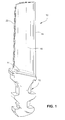
- a stage 1 gas turbine engine bucket 10 may include a dovetail mounting portion 12, a platform 14 at the radially outer end of the dovetail portion and a radially outwardly extending airfoil portion 16.
- the airfoil portion is formed with a leading edge 18 and a trailing edge 20.
- a cooling circuit is cast within the interior of the bucket, and specifically within the airfoil portion, that includes a serpentine array of cooling passages that terminate along the trailing edge 20 of the bucket where cooling air exits the airfoil via a plurality of apertures.
- the cooling circuit is formed with the aid of a casting core of the type shown on Figure 3.
- the casting core 22 includes an inlet portion 24 and a plurality of side-by-side (substantially parallel) solid portions (or legs) 26, 28, 30, 32 and 34 which, after casting and after removal of the core material, form the cooling air inlet and cooling air passages, respectively.
- the empty space between the solid portions of the core thus become solid internal ribs that separate cooling passages within the bucket.
- the core support pins 36 and 38 which are employed primarily to strengthen the core so that it does not break during the casting process.
- the cooling passages formed by the internal casting core are shown at 40, 42, 44, 46 and 48.
- Figure 2 also illustrates the cross-over holes 50 and 52 created by the pins 36, 38.
- the pins 36, 38 are made round in cross section, thus also creating the round cross-over holes 52, 54. This change eliminates or at least reduces the high stress regions and minimizes if not eliminates the possibility of casting defects in those regions.
- the pins 36 and 38 are simply eliminated, and no cross over holes between cooling passages are established.
Landscapes
- Engineering & Computer Science (AREA)
- Mechanical Engineering (AREA)
- General Engineering & Computer Science (AREA)
- Turbine Rotor Nozzle Sealing (AREA)
- Molds, Cores, And Manufacturing Methods Thereof (AREA)
Applications Claiming Priority (1)
| Application Number | Priority Date | Filing Date | Title |
|---|---|---|---|
| US11/493,021 US20080028606A1 (en) | 2006-07-26 | 2006-07-26 | Low stress turbins bucket |
Publications (1)
| Publication Number | Publication Date |
|---|---|
| EP1895097A2 true EP1895097A2 (fr) | 2008-03-05 |
Family
ID=38894058
Family Applications (1)
| Application Number | Title | Priority Date | Filing Date |
|---|---|---|---|
| EP07112069A Withdrawn EP1895097A2 (fr) | 2006-07-26 | 2007-07-09 | Aube de turbine à faible contrainte |
Country Status (4)
| Country | Link |
|---|---|
| US (1) | US20080028606A1 (fr) |
| EP (1) | EP1895097A2 (fr) |
| JP (1) | JP2008031995A (fr) |
| CN (1) | CN101113676A (fr) |
Cited By (1)
| Publication number | Priority date | Publication date | Assignee | Title |
|---|---|---|---|---|
| EP2946079A4 (fr) * | 2013-01-15 | 2016-06-22 | United Technologies Corp | Élément de moteur de turbine à gaz, doté de nervures d'impact inclinées transversalement |
Families Citing this family (9)
| Publication number | Priority date | Publication date | Assignee | Title |
|---|---|---|---|---|
| JP5254675B2 (ja) * | 2008-06-16 | 2013-08-07 | 三菱重工業株式会社 | タービン翼製造用中子およびタービン翼の製造方法 |
| EP2700787B1 (fr) | 2011-04-22 | 2018-04-04 | Mitsubishi Hitachi Power Systems, Ltd. | Aube et machine rotative |
| US9376922B2 (en) | 2013-01-09 | 2016-06-28 | General Electric Company | Interior configuration for turbine rotor blade |
| US9120144B2 (en) * | 2013-02-06 | 2015-09-01 | Siemens Aktiengesellschaft | Casting core for twisted gas turbine engine airfoil having a twisted rib |
| JP6216618B2 (ja) * | 2013-11-12 | 2017-10-18 | 三菱日立パワーシステムズ株式会社 | ガスタービン翼の製造方法 |
| EP2944762B1 (fr) * | 2014-05-12 | 2016-12-21 | General Electric Technology GmbH | Profil aérodynamique avec refroidissement amélioré |
| FR3056631B1 (fr) * | 2016-09-29 | 2018-10-19 | Safran | Circuit de refroidissement ameliore pour aubes |
| US10753210B2 (en) * | 2018-05-02 | 2020-08-25 | Raytheon Technologies Corporation | Airfoil having improved cooling scheme |
| US12203390B1 (en) * | 2023-07-07 | 2025-01-21 | General Electric Company | Composite airfoil assembly for a turbine engine |
Family Cites Families (11)
| Publication number | Priority date | Publication date | Assignee | Title |
|---|---|---|---|---|
| US3533712A (en) * | 1966-02-26 | 1970-10-13 | Gen Electric | Cooled vane structure for high temperature turbines |
| US4497613A (en) * | 1983-01-26 | 1985-02-05 | General Electric Company | Tapered core exit for gas turbine bucket |
| US4526512A (en) * | 1983-03-28 | 1985-07-02 | General Electric Co. | Cooling flow control device for turbine blades |
| US4923371A (en) * | 1988-04-01 | 1990-05-08 | General Electric Company | Wall having cooling passage |
| US5947181A (en) * | 1996-07-10 | 1999-09-07 | General Electric Co. | Composite, internal reinforced ceramic cores and related methods |
| US6340047B1 (en) * | 1999-03-22 | 2002-01-22 | General Electric Company | Core tied cast airfoil |
| US6234753B1 (en) * | 1999-05-24 | 2001-05-22 | General Electric Company | Turbine airfoil with internal cooling |
| US6186741B1 (en) * | 1999-07-22 | 2001-02-13 | General Electric Company | Airfoil component having internal cooling and method of cooling |
| US6164914A (en) * | 1999-08-23 | 2000-12-26 | General Electric Company | Cool tip blade |
| US6966756B2 (en) * | 2004-01-09 | 2005-11-22 | General Electric Company | Turbine bucket cooling passages and internal core for producing the passages |
| US7216694B2 (en) * | 2004-01-23 | 2007-05-15 | United Technologies Corporation | Apparatus and method for reducing operating stress in a turbine blade and the like |
-
2006
- 2006-07-26 US US11/493,021 patent/US20080028606A1/en not_active Abandoned
-
2007
- 2007-07-09 EP EP07112069A patent/EP1895097A2/fr not_active Withdrawn
- 2007-07-12 JP JP2007182707A patent/JP2008031995A/ja not_active Withdrawn
- 2007-07-26 CN CN200710136997.3A patent/CN101113676A/zh active Pending
Cited By (1)
| Publication number | Priority date | Publication date | Assignee | Title |
|---|---|---|---|---|
| EP2946079A4 (fr) * | 2013-01-15 | 2016-06-22 | United Technologies Corp | Élément de moteur de turbine à gaz, doté de nervures d'impact inclinées transversalement |
Also Published As
| Publication number | Publication date |
|---|---|
| JP2008031995A (ja) | 2008-02-14 |
| US20080028606A1 (en) | 2008-02-07 |
| CN101113676A (zh) | 2008-01-30 |
Similar Documents
| Publication | Publication Date | Title |
|---|---|---|
| EP1895097A2 (fr) | Aube de turbine à faible contrainte | |
| CN100359134C (zh) | 根部开有缺口的涡轮叶片 | |
| EP2233697B1 (fr) | Ensemble d'aubes de guidage pour une turbine | |
| KR100573658B1 (ko) | 터빈 요소 | |
| JP4453826B2 (ja) | 3回路タービンブレード | |
| US6109868A (en) | Reduced-length high flow interstage air extraction | |
| US9279331B2 (en) | Gas turbine engine airfoil with dirt purge feature and core for making same | |
| US20140271225A1 (en) | Interior cooling circuits in turbine blades | |
| JP5911680B2 (ja) | バケット組立体冷却装置及びバケット組立体の形成方法 | |
| US20120152484A1 (en) | Peripheral microcircuit serpentine cooling for turbine airfoils | |
| US9689265B2 (en) | Thin-walled reinforcement lattice structure for hollow CMC buckets | |
| EP1055800A2 (fr) | Aube de turbine avec refroidissement interne | |
| US20140010666A1 (en) | Airfoil cooling circuits | |
| US8628300B2 (en) | Apparatus and methods for cooling platform regions of turbine rotor blades | |
| US20060269408A1 (en) | Turbine airfoil trailing edge cooling system with segmented impingement ribs | |
| US20140064983A1 (en) | Airfoil and method for manufacturing an airfoil | |
| US20160017716A1 (en) | A turbomachine component with a stress relief cavity | |
| JP2007537384A (ja) | ブレードの固定軽減不整合 | |
| EP1593812B1 (fr) | Aube de turbine refroidie | |
| EP1106280A1 (fr) | Noyau pour controler l'épaisseur d'une aube d'une turbine et méthode | |
| CN103261584B (zh) | 涡轮机部件、置于其中空翼型内的冲击管及其组装方法 | |
| CN101845970A (zh) | 涡轮机转子组件和方法 | |
| CN101165318A (zh) | 涡轮机组件所用翼型及其装配方法 | |
| US7207775B2 (en) | Turbine bucket with optimized cooling circuit | |
| JP4663479B2 (ja) | ガスタービンロータブレード |
Legal Events
| Date | Code | Title | Description |
|---|---|---|---|
| PUAI | Public reference made under article 153(3) epc to a published international application that has entered the european phase |
Free format text: ORIGINAL CODE: 0009012 |
|
| AK | Designated contracting states |
Kind code of ref document: A2 Designated state(s): AT BE BG CH CY CZ DE DK EE ES FI FR GB GR HU IE IS IT LI LT LU LV MC MT NL PL PT RO SE SI SK TR |
|
| AX | Request for extension of the european patent |
Extension state: AL BA HR MK YU |
|
| RIN1 | Information on inventor provided before grant (corrected) |
Inventor name: BALKCULM III, J. TYSON Inventor name: WEBER, JOSEPH A. Inventor name: KRISHNAKUMAR, POORNATHRESAN |
|
| STAA | Information on the status of an ep patent application or granted ep patent |
Free format text: STATUS: THE APPLICATION IS DEEMED TO BE WITHDRAWN |
|
| 18D | Application deemed to be withdrawn |
Effective date: 20110201 |