EP1895151A2 - Procédé pour régler le banc d'essai d'une unité pompe-buse - Google Patents
Procédé pour régler le banc d'essai d'une unité pompe-buse Download PDFInfo
- Publication number
- EP1895151A2 EP1895151A2 EP07112117A EP07112117A EP1895151A2 EP 1895151 A2 EP1895151 A2 EP 1895151A2 EP 07112117 A EP07112117 A EP 07112117A EP 07112117 A EP07112117 A EP 07112117A EP 1895151 A2 EP1895151 A2 EP 1895151A2
- Authority
- EP
- European Patent Office
- Prior art keywords
- camshaft
- cam
- injection system
- stroke
- test device
- Prior art date
- Legal status (The legal status is an assumption and is not a legal conclusion. Google has not performed a legal analysis and makes no representation as to the accuracy of the status listed.)
- Granted
Links
Images


Classifications
-
- F—MECHANICAL ENGINEERING; LIGHTING; HEATING; WEAPONS; BLASTING
- F02—COMBUSTION ENGINES; HOT-GAS OR COMBUSTION-PRODUCT ENGINE PLANTS
- F02M—SUPPLYING COMBUSTION ENGINES IN GENERAL WITH COMBUSTIBLE MIXTURES OR CONSTITUENTS THEREOF
- F02M65/00—Testing fuel-injection apparatus, e.g. testing injection timing ; Cleaning of fuel-injection apparatus
-
- F—MECHANICAL ENGINEERING; LIGHTING; HEATING; WEAPONS; BLASTING
- F02—COMBUSTION ENGINES; HOT-GAS OR COMBUSTION-PRODUCT ENGINE PLANTS
- F02M—SUPPLYING COMBUSTION ENGINES IN GENERAL WITH COMBUSTIBLE MIXTURES OR CONSTITUENTS THEREOF
- F02M57/00—Fuel-injectors combined or associated with other devices
- F02M57/02—Injectors structurally combined with fuel-injection pumps
- F02M57/022—Injectors structurally combined with fuel-injection pumps characterised by the pump drive
- F02M57/023—Injectors structurally combined with fuel-injection pumps characterised by the pump drive mechanical
Definitions
- the invention relates to a test device for a cam-driven fuel injection system, in particular a pump-nozzle or pump-line-nozzle injection system, according to the preamble of claim 1.
- the fuel is injected directly from a fuel injection system under high pressure into the combustion chamber.
- Various types of fuel injection systems are used, for example, pump-nozzle injection systems or pump-line-nozzle injection systems. Both fuel injection systems are actuated on the engine itself via a camshaft. A cam on the camshaft causes via a lever a stroke of a pump piston of the fuel injection system. This generates at a nozzle of the fuel injection system, a very high pressure, displaced by a valve needle in an open position and so fuel is injected into a combustion chamber of the engine. The injection quantity is adjusted via a solenoid valve which controls the pressure build-up in the fuel injection system.
- the injection pressure and the injection quantity depend inter alia on the shape of the cam and its stroke. Different fuel injection systems have different strokes and cam shapes. In part, identical fuel injection systems are operated with identical stroke in different types of engines with different cams.
- test devices are known from the market.
- a cam-driven fuel injection system is installed. Via a camshaft and a lever, the piston of the fuel injection system is acted upon and thereby simulated an operation.
- the actuation of the injection system by the cam of the test device must be simulated. Furthermore, when a predetermined stroke of the cam is reached, a solenoid valve in the injection system must be actuated via a control device belonging to the test device.
- the control of the solenoid valve must be done at a defined stroke of the cam to produce the correct injection pressure and injection quantity. Since the detection of the stroke is more complicated than the detection of the rotational angle of the camshaft, the control of the solenoid valve is usually carried out in dependence on a predetermined rotational angle of the camshaft. In order to adapt the test apparatus to the injection system to be tested, an adjustment of the cam is carried out in test devices available on the market. For this purpose, the base circle of the cam is determined with a dial gauge and the dial gauge is set to zero. Then, the camshaft is rotated in the direction as long as it is rotated during the test, until a predetermined stroke, which depends on the shape of the cam is reached.
- This predetermined stroke, a rotation angle of the camshaft is permanently assigned. Therefore, it is possible, after reaching the predetermined stroke, a giver of the test device to rotate relative to the camshaft that exactly at this hub, a control signal is output from the encoder.
- the test apparatus for testing the injection system to be tested is set and the test of the injection system can be made.
- a disadvantage of this method is that when changing the injection system to be tested, the tester must be set again. The reason for this is that different types of injection systems require a different stroke and consequently a different cam angle as a start signal for the control of the solenoid valve in the injection system.
- the invention has for its object to provide a method and a setting for a test apparatus and an improved test device in which incorrect settings can be avoided and in which the change of the injection system to be tested requires less time for retooling the tester.
- This object is achieved in a test device for a cam-driven fuel injection system with a camshaft, which can act at least indirectly on a piston of the fuel injection system to be tested, achieved in that directly or indirectly to the camshaft, a high-resolution angle of rotation sensor is arranged.
- the test device according to the invention has a camshaft with a plurality of juxtaposed different cams and a lever which transmits the control movements of the cam on a pump element of the injection system to be tested, together with a fastening device for the fuel injection device to be tested in axial direction of the camshaft is displaceable in different operating positions, wherein the lever cooperates in each operating position with another cam.
- the advantages of the invention are achieved in carrying out a method according to the invention for adjusting a test device for a cam-driven fuel injection system, comprising the following steps: detecting a base circle at least one cam of a camshaft, rotating the camshaft until a predetermined stroke of the at least one cam is reached , Detecting the correlation with the given stroke of the at least one cam angle of rotation of the camshaft and storing the angle of rotation and stroke on a storage medium.
- the reference signal is emitted between 30 ° and 10 ° before reaching the zero stroke of the camshaft.
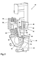
- a testing device carries in FIGS. 1 and 2 the reference numeral 10 as a whole. It is used to test a cam-driven fuel injection system, in the present example a pump-nozzle injection system 12, which however is shown only in FIG. First, its structure and function are explained.
- the pump-nozzle injection system 12 comprises a housing 14 with a nozzle tip 16 which projects into an injection chamber 18 of the test apparatus 10.
- a nozzle needle 20 is slidably received, which is acted upon by a spring 22 in a closed position.
- a pump of the pump-nozzle injection system 12 is designated by 24 and comprises a piston 26 which delimits a delivery space 28. This is connected to a pressure chamber 30 which is delimited by a pressure surface 32 formed on the nozzle needle 20 and acting in its opening direction.
- the delivery chamber 28 is further connected via a magnetic control valve 34 and a feed pump 36 with a fluid container 38, in which a test fluid is stored in the present case.
- test fluid is sucked out of the fluid container 38 into the delivery chamber 28 when the control valve 34 is open.
- the control valve 34 is closed, the test fluid enclosed in the delivery chamber 28 is compressed during a delivery stroke of the piston 26, which leads to a corresponding pressure increase in the pressure chamber 30. If the hydraulic force acting on the pressure surface 32 exceeds the force of the spring 22, the nozzle needle 20 opens and test fluid is injected from the nozzle tip 16 into the injection chamber 18, where it is collected and passed on.
- test apparatus 10 For testing the pump-nozzle injection system 12, the test apparatus 10 has two essential sub-apparatuses: an actuator 40 and a fixture 42. First to the latter:
- the fastening device 42 comprises a guide plate 44 with a plurality of mutually parallel guide grooves 46, of which, for reasons of clarity, only one carries a reference numeral.
- guide grooves 46 By means of these guide grooves 46, different attachment positions are defined for an adapter element designed as an adapter plate 48.
- the housing 14 of the pump-nozzle injection system 12 is fixed in a manner not shown here.
- the guide plate 44 is articulated in 50 to a stationary base 52 of the test apparatus 10. In order to prevent tilting of the guide plate 44 during operation, this is supported at its end remote from the joint 50 via a pendulum support 54 on a bearing block 56, which is also connected to the stationary base 52. On the bearing block 56 designed as a strain gauge 58 sensor is arranged, which detects a force acting on the bearing block 56 via the pendulum support 54 transverse force.
- the actuator 40 is constructed as follows.
- a drag lever 60 is pivotally mounted in 62 again on the stationary base 52.
- the pivot joint 62 is laterally spaced from a longitudinal axis 64 of the piston 26 of the pump-nozzle injection system 12.
- An arm 66 of the finger lever 60 extends to the piston 26 back.
- an intermediate element forming an intermediate plate 68 is fixed, in which a plurality of threaded holes 70 are present (for illustrative reasons, again only one provided with a reference numeral).
- the threaded holes 70 are spaced from the defined by the hinge 62 pivot axis of the finger lever 60 different.
- the ball head of the actuator 22 cooperates with a complementary recess (without reference numeral) in the piston 26 of the pump-nozzle injection system 12 together.
- a roller holder 74 with a roller 76 is arranged on this. This in turn cooperates with a cam 78 of a camshaft 80. This is driven by a drive motor, not shown here, for example an electric motor.
- a second arm 82 of the drag lever 60 is acted upon by a compression spring 84 which is clamped between the arm 82 and in turn the stationary base 52. In this way, the roller 76 is constantly pressed against the cam 78.
- the test apparatus 10 operates as follows: Upon rotation of the camshaft 80, the drag lever 60 is pivoted about its pivot axis 62. Due to the lever arm between the actuating element 72 and the pivot axis defined by the joint 62 (this lever arm is designated by 86 in FIG. 1), a specific stroke results for each threaded bore 70. This is at the threaded hole 70, in which the actuator 72 is screwed in Figure 1, the lowest. Accordingly, there is a comparatively small stroke of the piston 26. The reaction force which is introduced by the pressure build-up in the delivery chamber 28 via the housing 14 and the adapter plate 48 in the guide plate 44 is transmitted via the pendulum support 54 in the bearing block 56 and there from the strain gauge 58 recorded.
- the adapter plate 48 is simply mounted in other guide grooves 46 on the guide plate 44 and the actuator 72 is screwed into another of the threaded holes 70. If another pump-injector system 12 is to be tested, another adapter plate 48 is used. Possible, but not shown, is that the guide grooves are individualized, so that each type of fuel injection system is assigned a specific mounting position and thus a specific hub unmistakable. In an embodiment also not shown, moreover, the fastening device can be moved together with the actuator (without camshaft) in the longitudinal direction of the camshaft. The corresponding camshaft then has a plurality of different and juxtaposed cams, so that depending on the position of the actuator, the roller cooperates with another cam.
- the rotation angle sensor 82 On the camshaft 80, a rotation angle sensor 82 is provided.
- the rotation angle sensor 82 has a very high resolution. It has proven in practical experiments to be sufficient if the resolution of the rotation angle sensor is less than 0.1 degrees.
- a zero stroke H 0 of the cam 78 is also entered in FIG. If, for example, a solenoid valve of the fuel injection system to be tested is to be controlled at a stroke H 1 , then the hub H 1 can be assigned an angle of rotation ⁇ 1 to the camshaft 80. In this case, for the zero stroke H 0 , the angle of rotation ⁇ 0 is equal to 0.
- the hub H 1 or other strokes H i each have a rotational angle ⁇ 1 or ⁇ i of the camshaft 80.
- the solenoid valve of the fuel injection system to be tested can then be activated as a function of the angle of rotation ⁇ .
- the rotation angle sensor 82 is not shown.
- FIG. 3 shows a flow chart of a method according to the invention for setting a test device according to the invention.
- the base circle of a cam 78 of a camshaft 80 is detected in a block 84.
- a further block 86 the camshaft 80 is rotated until a predetermined stroke H 1 is reached.
- the rotation angle ⁇ 1 associated with this stroke H 1 is detected and stored in a third block 88 on a storage medium.
- the blocks 86 and 88 are traversed so many times, until each test H; a rotation angle ⁇ i of the camshaft 80 is detected and stored.
- the test device can be delivered and used by the customer. Due to the individual assignment of the rotation angle ⁇ i to the test strokes H; Also possible manufacturing inaccuracies, for example, in the contour of the cam 78 can be eliminated, so that all delivered test devices have an identical accuracy.
- FIG. 4 shows a side view of a camshaft 80 with a cam 78.
- a reference signal of the angle sensor 82 is delivered 10 ° to 30 ° before reaching the zero stroke.
- the area within which advantageously the reference signal of the rotation angle sensor 82 is emitted is designated by the reference numeral 90 in FIG.
Landscapes
- Engineering & Computer Science (AREA)
- Chemical & Material Sciences (AREA)
- Combustion & Propulsion (AREA)
- Mechanical Engineering (AREA)
- General Engineering & Computer Science (AREA)
- Fuel-Injection Apparatus (AREA)
Applications Claiming Priority (1)
| Application Number | Priority Date | Filing Date | Title |
|---|---|---|---|
| DE200610041072 DE102006041072A1 (de) | 2006-09-01 | 2006-09-01 | Verfahren zum Justieren einer Prüfvorrichtung für ein nockengetriebenes Kraftstoff-Einspritzsystem, insbesondere ein Pumpe-Düse-oder Pumpe-Leitung-Düse-Einspritzsystem |
Publications (3)
| Publication Number | Publication Date |
|---|---|
| EP1895151A2 true EP1895151A2 (fr) | 2008-03-05 |
| EP1895151A3 EP1895151A3 (fr) | 2009-06-17 |
| EP1895151B1 EP1895151B1 (fr) | 2015-10-21 |
Family
ID=38421512
Family Applications (1)
| Application Number | Title | Priority Date | Filing Date |
|---|---|---|---|
| EP07112117.2A Active EP1895151B1 (fr) | 2006-09-01 | 2007-07-10 | Banc d'essai d'une unité pompe-buse et procédé pour régler le banc d'essai d'une unité pompe-buse |
Country Status (2)
| Country | Link |
|---|---|
| EP (1) | EP1895151B1 (fr) |
| DE (1) | DE102006041072A1 (fr) |
Cited By (1)
| Publication number | Priority date | Publication date | Assignee | Title |
|---|---|---|---|---|
| KR102460186B1 (ko) * | 2022-08-24 | 2022-10-31 | (주)한미유압기계 | 마이크로 파일럿 부스터 인젝터 밸브와 슬라이드 밸브의 테스트가 가능한 선박 엔진용 연료분사밸브 검사 장치 |
Families Citing this family (1)
| Publication number | Priority date | Publication date | Assignee | Title |
|---|---|---|---|---|
| DE102013221242A1 (de) * | 2013-10-21 | 2015-04-23 | Volkswagen Aktiengesellschaft | Verfahren zum Betreiben eines Verbrennungsmotors |
Family Cites Families (4)
| Publication number | Priority date | Publication date | Assignee | Title |
|---|---|---|---|---|
| JP3818607B2 (ja) * | 1997-01-27 | 2006-09-06 | 株式会社小松製作所 | カム駆動式の電子制御ユニットインジェクタの制御装置及びその制御方法 |
| DE10146772C2 (de) * | 2001-09-22 | 2003-09-25 | Orange Gmbh | Messvorrichtung zum Messen des Kolbenhubes einer Kraftstoffeinspritzpumpe |
| US7089789B2 (en) * | 2002-03-19 | 2006-08-15 | Stanadyne Corporation | System for calibrating an integrated injection nozzle and injection pump |
| JP4111956B2 (ja) * | 2005-01-14 | 2008-07-02 | 三菱電機株式会社 | 内燃機関の燃料供給装置 |
-
2006
- 2006-09-01 DE DE200610041072 patent/DE102006041072A1/de not_active Withdrawn
-
2007
- 2007-07-10 EP EP07112117.2A patent/EP1895151B1/fr active Active
Cited By (1)
| Publication number | Priority date | Publication date | Assignee | Title |
|---|---|---|---|---|
| KR102460186B1 (ko) * | 2022-08-24 | 2022-10-31 | (주)한미유압기계 | 마이크로 파일럿 부스터 인젝터 밸브와 슬라이드 밸브의 테스트가 가능한 선박 엔진용 연료분사밸브 검사 장치 |
Also Published As
| Publication number | Publication date |
|---|---|
| EP1895151A3 (fr) | 2009-06-17 |
| DE102006041072A1 (de) | 2008-03-06 |
| EP1895151B1 (fr) | 2015-10-21 |
Similar Documents
| Publication | Publication Date | Title |
|---|---|---|
| EP1520097B1 (fr) | Dispositif d'amortissement de levee de l'aiguille d'un injecteur de carburant | |
| DE2527757A1 (de) | Brennkraftmaschine und bei dieser verwendbare kraftstoffpumpe | |
| DE102008042412A1 (de) | Steuergerät für ein Druckspeicherkraftstoffeinspritzsystem | |
| DE69923108T2 (de) | Brennstoffsystem und Pumpe zur Anwendung in einem solchen System | |
| DE69418801T2 (de) | System zur Steuerung der Voreinspritzung | |
| EP0290797A2 (fr) | Pompe d'injection de combustible | |
| DE3600113A1 (de) | Kraftstoff-einspritzeinrichtung fuer einen verbrennungsmotor | |
| EP1103718B1 (fr) | Réglage de la course entre un actionneur et un élément de transmission pour une soupape dans un injecteur de combustible | |
| DE3382635T2 (de) | Verfahren und geraet fuer die genaue steuerung der kraftstoffeinspritzung in einer brennkraftmaschine. | |
| EP1895151B1 (fr) | Banc d'essai d'une unité pompe-buse et procédé pour régler le banc d'essai d'une unité pompe-buse | |
| EP0752061B1 (fr) | Systeme permettant d'injecter du carburant dans les cylindres d'un moteur a combustion interne | |
| DE10317610A1 (de) | Kraftstoffeinspritzvorrichtung | |
| DE69406982T2 (de) | Kraftstoffeinspritzventil für Verbrennungsmotor | |
| DE102014007963A1 (de) | Verfahren zum Betreiben einer Brennkraftmaschine und Motorsteuergerät | |
| EP1531258A2 (fr) | Injecteur de combustible | |
| WO2005124153A1 (fr) | Pompe haute pression conçue pour un dispositif d'injection de carburant d'un moteur a combustion interne | |
| DE3102801C2 (fr) | ||
| EP1969226B1 (fr) | Dispositif de test pour un system d'injection de carburant entraine par came, en particulier un systeme d'injection par gicleur et pompe ou par gicleur, conduit et pompe | |
| DE102004022641B4 (de) | Treibstoffförderpumpe einer Brennkraftmaschine | |
| DE10307002A1 (de) | Kraftstoffeinspritzdüse und Pumpe-Düse-Einheit | |
| WO2009156205A1 (fr) | Corps d'appui, clapet antiretour et pompe à carburant à haute pression | |
| DE112006001426T5 (de) | Brennstoffeinspritzvorrichtungssteuersystem und -verfahren | |
| WO2016059050A1 (fr) | Procédé permettant de faire fonctionner un système d'alimentation en carburant de moteur à combustion interne | |
| DE3802136C2 (de) | Pumpedüse, insbesondere für direkt einspritzende Diesel-Brennkraftmaschinen | |
| DE102007033889A1 (de) | Kraftstoffpumpe für ein Einspritzsystem einer Brennkraftmaschine |
Legal Events
| Date | Code | Title | Description |
|---|---|---|---|
| PUAI | Public reference made under article 153(3) epc to a published international application that has entered the european phase |
Free format text: ORIGINAL CODE: 0009012 |
|
| AK | Designated contracting states |
Kind code of ref document: A2 Designated state(s): AT BE BG CH CY CZ DE DK EE ES FI FR GB GR HU IE IS IT LI LT LU LV MC MT NL PL PT RO SE SI SK TR |
|
| AX | Request for extension of the european patent |
Extension state: AL BA HR MK YU |
|
| PUAL | Search report despatched |
Free format text: ORIGINAL CODE: 0009013 |
|
| AK | Designated contracting states |
Kind code of ref document: A3 Designated state(s): AT BE BG CH CY CZ DE DK EE ES FI FR GB GR HU IE IS IT LI LT LU LV MC MT NL PL PT RO SE SI SK TR |
|
| AX | Request for extension of the european patent |
Extension state: AL BA HR MK RS |
|
| 17P | Request for examination filed |
Effective date: 20091217 |
|
| 17Q | First examination report despatched |
Effective date: 20100121 |
|
| AKX | Designation fees paid |
Designated state(s): AT BE BG CH CY CZ DE DK EE ES FI FR GB GR HU IE IS IT LI LT LU LV MC MT NL PL PT RO SE SI SK TR |
|
| REG | Reference to a national code |
Ref country code: DE Ref legal event code: R079 Ref document number: 502007014332 Country of ref document: DE Free format text: PREVIOUS MAIN CLASS: F02M0057020000 Ipc: F02M0065000000 |
|
| RIC1 | Information provided on ipc code assigned before grant |
Ipc: F02M 57/02 20060101ALI20150320BHEP Ipc: F02M 65/00 20060101AFI20150320BHEP |
|
| GRAP | Despatch of communication of intention to grant a patent |
Free format text: ORIGINAL CODE: EPIDOSNIGR1 |
|
| INTG | Intention to grant announced |
Effective date: 20150730 |
|
| GRAS | Grant fee paid |
Free format text: ORIGINAL CODE: EPIDOSNIGR3 |
|
| GRAA | (expected) grant |
Free format text: ORIGINAL CODE: 0009210 |
|
| AK | Designated contracting states |
Kind code of ref document: B1 Designated state(s): AT BE BG CH CY CZ DE DK EE ES FI FR GB GR HU IE IS IT LI LT LU LV MC MT NL PL PT RO SE SI SK TR |
|
| REG | Reference to a national code |
Ref country code: GB Ref legal event code: FG4D Free format text: NOT ENGLISH Ref country code: NL Ref legal event code: MP Effective date: 20151021 |
|
| REG | Reference to a national code |
Ref country code: CH Ref legal event code: EP |
|
| REG | Reference to a national code |
Ref country code: AT Ref legal event code: REF Ref document number: 756780 Country of ref document: AT Kind code of ref document: T Effective date: 20151115 |
|
| REG | Reference to a national code |
Ref country code: IE Ref legal event code: FG4D Free format text: LANGUAGE OF EP DOCUMENT: GERMAN |
|
| REG | Reference to a national code |
Ref country code: DE Ref legal event code: R096 Ref document number: 502007014332 Country of ref document: DE |
|
| REG | Reference to a national code |
Ref country code: LT Ref legal event code: MG4D |
|
| PG25 | Lapsed in a contracting state [announced via postgrant information from national office to epo] |
Ref country code: NL Free format text: LAPSE BECAUSE OF FAILURE TO SUBMIT A TRANSLATION OF THE DESCRIPTION OR TO PAY THE FEE WITHIN THE PRESCRIBED TIME-LIMIT Effective date: 20151021 Ref country code: IS Free format text: LAPSE BECAUSE OF FAILURE TO SUBMIT A TRANSLATION OF THE DESCRIPTION OR TO PAY THE FEE WITHIN THE PRESCRIBED TIME-LIMIT Effective date: 20160221 Ref country code: ES Free format text: LAPSE BECAUSE OF FAILURE TO SUBMIT A TRANSLATION OF THE DESCRIPTION OR TO PAY THE FEE WITHIN THE PRESCRIBED TIME-LIMIT Effective date: 20151021 Ref country code: LT Free format text: LAPSE BECAUSE OF FAILURE TO SUBMIT A TRANSLATION OF THE DESCRIPTION OR TO PAY THE FEE WITHIN THE PRESCRIBED TIME-LIMIT Effective date: 20151021 |
|
| PG25 | Lapsed in a contracting state [announced via postgrant information from national office to epo] |
Ref country code: LV Free format text: LAPSE BECAUSE OF FAILURE TO SUBMIT A TRANSLATION OF THE DESCRIPTION OR TO PAY THE FEE WITHIN THE PRESCRIBED TIME-LIMIT Effective date: 20151021 Ref country code: PT Free format text: LAPSE BECAUSE OF FAILURE TO SUBMIT A TRANSLATION OF THE DESCRIPTION OR TO PAY THE FEE WITHIN THE PRESCRIBED TIME-LIMIT Effective date: 20160222 Ref country code: PL Free format text: LAPSE BECAUSE OF FAILURE TO SUBMIT A TRANSLATION OF THE DESCRIPTION OR TO PAY THE FEE WITHIN THE PRESCRIBED TIME-LIMIT Effective date: 20151021 Ref country code: GR Free format text: LAPSE BECAUSE OF FAILURE TO SUBMIT A TRANSLATION OF THE DESCRIPTION OR TO PAY THE FEE WITHIN THE PRESCRIBED TIME-LIMIT Effective date: 20160122 Ref country code: FI Free format text: LAPSE BECAUSE OF FAILURE TO SUBMIT A TRANSLATION OF THE DESCRIPTION OR TO PAY THE FEE WITHIN THE PRESCRIBED TIME-LIMIT Effective date: 20151021 Ref country code: SE Free format text: LAPSE BECAUSE OF FAILURE TO SUBMIT A TRANSLATION OF THE DESCRIPTION OR TO PAY THE FEE WITHIN THE PRESCRIBED TIME-LIMIT Effective date: 20151021 |
|
| REG | Reference to a national code |
Ref country code: DE Ref legal event code: R097 Ref document number: 502007014332 Country of ref document: DE |
|
| PG25 | Lapsed in a contracting state [announced via postgrant information from national office to epo] |
Ref country code: CZ Free format text: LAPSE BECAUSE OF FAILURE TO SUBMIT A TRANSLATION OF THE DESCRIPTION OR TO PAY THE FEE WITHIN THE PRESCRIBED TIME-LIMIT Effective date: 20151021 |
|
| PLBE | No opposition filed within time limit |
Free format text: ORIGINAL CODE: 0009261 |
|
| STAA | Information on the status of an ep patent application or granted ep patent |
Free format text: STATUS: NO OPPOSITION FILED WITHIN TIME LIMIT |
|
| PG25 | Lapsed in a contracting state [announced via postgrant information from national office to epo] |
Ref country code: DK Free format text: LAPSE BECAUSE OF FAILURE TO SUBMIT A TRANSLATION OF THE DESCRIPTION OR TO PAY THE FEE WITHIN THE PRESCRIBED TIME-LIMIT Effective date: 20151021 Ref country code: RO Free format text: LAPSE BECAUSE OF FAILURE TO SUBMIT A TRANSLATION OF THE DESCRIPTION OR TO PAY THE FEE WITHIN THE PRESCRIBED TIME-LIMIT Effective date: 20151021 Ref country code: SK Free format text: LAPSE BECAUSE OF FAILURE TO SUBMIT A TRANSLATION OF THE DESCRIPTION OR TO PAY THE FEE WITHIN THE PRESCRIBED TIME-LIMIT Effective date: 20151021 Ref country code: EE Free format text: LAPSE BECAUSE OF FAILURE TO SUBMIT A TRANSLATION OF THE DESCRIPTION OR TO PAY THE FEE WITHIN THE PRESCRIBED TIME-LIMIT Effective date: 20151021 |
|
| 26N | No opposition filed |
Effective date: 20160722 |
|
| PG25 | Lapsed in a contracting state [announced via postgrant information from national office to epo] |
Ref country code: SI Free format text: LAPSE BECAUSE OF FAILURE TO SUBMIT A TRANSLATION OF THE DESCRIPTION OR TO PAY THE FEE WITHIN THE PRESCRIBED TIME-LIMIT Effective date: 20151021 |
|
| PG25 | Lapsed in a contracting state [announced via postgrant information from national office to epo] |
Ref country code: BE Free format text: LAPSE BECAUSE OF NON-PAYMENT OF DUE FEES Effective date: 20160731 |
|
| REG | Reference to a national code |
Ref country code: CH Ref legal event code: PL |
|
| PG25 | Lapsed in a contracting state [announced via postgrant information from national office to epo] |
Ref country code: MC Free format text: LAPSE BECAUSE OF FAILURE TO SUBMIT A TRANSLATION OF THE DESCRIPTION OR TO PAY THE FEE WITHIN THE PRESCRIBED TIME-LIMIT Effective date: 20151021 |
|
| PG25 | Lapsed in a contracting state [announced via postgrant information from national office to epo] |
Ref country code: LI Free format text: LAPSE BECAUSE OF NON-PAYMENT OF DUE FEES Effective date: 20160731 Ref country code: CH Free format text: LAPSE BECAUSE OF NON-PAYMENT OF DUE FEES Effective date: 20160731 Ref country code: FR Free format text: LAPSE BECAUSE OF NON-PAYMENT OF DUE FEES Effective date: 20160801 |
|
| REG | Reference to a national code |
Ref country code: FR Ref legal event code: ST Effective date: 20170331 |
|
| REG | Reference to a national code |
Ref country code: IE Ref legal event code: MM4A |
|
| PG25 | Lapsed in a contracting state [announced via postgrant information from national office to epo] |
Ref country code: IE Free format text: LAPSE BECAUSE OF NON-PAYMENT OF DUE FEES Effective date: 20160710 |
|
| PG25 | Lapsed in a contracting state [announced via postgrant information from national office to epo] |
Ref country code: LU Free format text: LAPSE BECAUSE OF NON-PAYMENT OF DUE FEES Effective date: 20160710 |
|
| REG | Reference to a national code |
Ref country code: AT Ref legal event code: MM01 Ref document number: 756780 Country of ref document: AT Kind code of ref document: T Effective date: 20160710 |
|
| PG25 | Lapsed in a contracting state [announced via postgrant information from national office to epo] |
Ref country code: AT Free format text: LAPSE BECAUSE OF NON-PAYMENT OF DUE FEES Effective date: 20160710 |
|
| PG25 | Lapsed in a contracting state [announced via postgrant information from national office to epo] |
Ref country code: HU Free format text: LAPSE BECAUSE OF FAILURE TO SUBMIT A TRANSLATION OF THE DESCRIPTION OR TO PAY THE FEE WITHIN THE PRESCRIBED TIME-LIMIT; INVALID AB INITIO Effective date: 20070710 Ref country code: CY Free format text: LAPSE BECAUSE OF FAILURE TO SUBMIT A TRANSLATION OF THE DESCRIPTION OR TO PAY THE FEE WITHIN THE PRESCRIBED TIME-LIMIT Effective date: 20151021 |
|
| PG25 | Lapsed in a contracting state [announced via postgrant information from national office to epo] |
Ref country code: MT Free format text: LAPSE BECAUSE OF FAILURE TO SUBMIT A TRANSLATION OF THE DESCRIPTION OR TO PAY THE FEE WITHIN THE PRESCRIBED TIME-LIMIT Effective date: 20151021 |
|
| PG25 | Lapsed in a contracting state [announced via postgrant information from national office to epo] |
Ref country code: BG Free format text: LAPSE BECAUSE OF FAILURE TO SUBMIT A TRANSLATION OF THE DESCRIPTION OR TO PAY THE FEE WITHIN THE PRESCRIBED TIME-LIMIT Effective date: 20151021 |
|
| PGFP | Annual fee paid to national office [announced via postgrant information from national office to epo] |
Ref country code: IT Payment date: 20200731 Year of fee payment: 14 |
|
| PG25 | Lapsed in a contracting state [announced via postgrant information from national office to epo] |
Ref country code: IT Free format text: LAPSE BECAUSE OF NON-PAYMENT OF DUE FEES Effective date: 20210710 |
|
| PGFP | Annual fee paid to national office [announced via postgrant information from national office to epo] |
Ref country code: DE Payment date: 20250924 Year of fee payment: 19 |
|
| PGFP | Annual fee paid to national office [announced via postgrant information from national office to epo] |
Ref country code: TR Payment date: 20250703 Year of fee payment: 19 |
|
| PGFP | Annual fee paid to national office [announced via postgrant information from national office to epo] |
Ref country code: GB Payment date: 20250724 Year of fee payment: 19 |