EP1895169A1 - Ensemble de soupapes de décharge et de contrôle - Google Patents
Ensemble de soupapes de décharge et de contrôle Download PDFInfo
- Publication number
- EP1895169A1 EP1895169A1 EP06425615A EP06425615A EP1895169A1 EP 1895169 A1 EP1895169 A1 EP 1895169A1 EP 06425615 A EP06425615 A EP 06425615A EP 06425615 A EP06425615 A EP 06425615A EP 1895169 A1 EP1895169 A1 EP 1895169A1
- Authority
- EP
- European Patent Office
- Prior art keywords
- opening
- obturator
- valve
- chamber
- towards
- Prior art date
- Legal status (The legal status is an assumption and is not a legal conclusion. Google has not performed a legal analysis and makes no representation as to the accuracy of the status listed.)
- Withdrawn
Links
- 238000006073 displacement reaction Methods 0.000 claims description 19
- 239000012530 fluid Substances 0.000 claims description 16
- 230000004913 activation Effects 0.000 claims description 4
- 238000007599 discharging Methods 0.000 description 1
- 238000007789 sealing Methods 0.000 description 1
- 238000009423 ventilation Methods 0.000 description 1
Images
Classifications
-
- F—MECHANICAL ENGINEERING; LIGHTING; HEATING; WEAPONS; BLASTING
- F15—FLUID-PRESSURE ACTUATORS; HYDRAULICS OR PNEUMATICS IN GENERAL
- F15B—SYSTEMS ACTING BY MEANS OF FLUIDS IN GENERAL; FLUID-PRESSURE ACTUATORS, e.g. SERVOMOTORS; DETAILS OF FLUID-PRESSURE SYSTEMS, NOT OTHERWISE PROVIDED FOR
- F15B11/00—Servomotor systems without provision for follow-up action; Circuits therefor
- F15B11/003—Systems with load-holding valves
-
- F—MECHANICAL ENGINEERING; LIGHTING; HEATING; WEAPONS; BLASTING
- F15—FLUID-PRESSURE ACTUATORS; HYDRAULICS OR PNEUMATICS IN GENERAL
- F15B—SYSTEMS ACTING BY MEANS OF FLUIDS IN GENERAL; FLUID-PRESSURE ACTUATORS, e.g. SERVOMOTORS; DETAILS OF FLUID-PRESSURE SYSTEMS, NOT OTHERWISE PROVIDED FOR
- F15B2211/00—Circuits for servomotor systems
- F15B2211/40—Flow control
- F15B2211/46—Control of flow in the return line, i.e. meter-out control
-
- F—MECHANICAL ENGINEERING; LIGHTING; HEATING; WEAPONS; BLASTING
- F15—FLUID-PRESSURE ACTUATORS; HYDRAULICS OR PNEUMATICS IN GENERAL
- F15B—SYSTEMS ACTING BY MEANS OF FLUIDS IN GENERAL; FLUID-PRESSURE ACTUATORS, e.g. SERVOMOTORS; DETAILS OF FLUID-PRESSURE SYSTEMS, NOT OTHERWISE PROVIDED FOR
- F15B2211/00—Circuits for servomotor systems
- F15B2211/50—Pressure control
- F15B2211/505—Pressure control characterised by the type of pressure control means
- F15B2211/50509—Pressure control characterised by the type of pressure control means the pressure control means controlling a pressure upstream of the pressure control means
- F15B2211/50518—Pressure control characterised by the type of pressure control means the pressure control means controlling a pressure upstream of the pressure control means using pressure relief valves
-
- F—MECHANICAL ENGINEERING; LIGHTING; HEATING; WEAPONS; BLASTING
- F15—FLUID-PRESSURE ACTUATORS; HYDRAULICS OR PNEUMATICS IN GENERAL
- F15B—SYSTEMS ACTING BY MEANS OF FLUIDS IN GENERAL; FLUID-PRESSURE ACTUATORS, e.g. SERVOMOTORS; DETAILS OF FLUID-PRESSURE SYSTEMS, NOT OTHERWISE PROVIDED FOR
- F15B2211/00—Circuits for servomotor systems
- F15B2211/50—Pressure control
- F15B2211/51—Pressure control characterised by the positions of the valve element
- F15B2211/513—Pressure control characterised by the positions of the valve element the positions being continuously variable, e.g. as realised by proportional valves
-
- F—MECHANICAL ENGINEERING; LIGHTING; HEATING; WEAPONS; BLASTING
- F15—FLUID-PRESSURE ACTUATORS; HYDRAULICS OR PNEUMATICS IN GENERAL
- F15B—SYSTEMS ACTING BY MEANS OF FLUIDS IN GENERAL; FLUID-PRESSURE ACTUATORS, e.g. SERVOMOTORS; DETAILS OF FLUID-PRESSURE SYSTEMS, NOT OTHERWISE PROVIDED FOR
- F15B2211/00—Circuits for servomotor systems
- F15B2211/70—Output members, e.g. hydraulic motors or cylinders or control therefor
- F15B2211/705—Output members, e.g. hydraulic motors or cylinders or control therefor characterised by the type of output members or actuators
- F15B2211/7051—Linear output members
- F15B2211/7053—Double-acting output members
Definitions
- the prior art includes high pressure and control valves for hydraulic actuators which are predisposed to be inserted in an activation circuit of a double-acting hydraulic actuator.
- the actuator is generally provided with a first opening, through which pressurised fluid can be sent to the actuator to determine a displacement in opposition to an external load, and a second opening, through which pressurised fluid can be sent to the actuator to determine a displacement which in agreement with the direction of the external load.
- the circuit further comprises a four-way three-position distributor which in a central position has at least one closed way which is predisposed to connect to the first opening of the actuator.
- the presence of the closed central way contributes to guaranteeing that under normal actuator rest conditions, the load is maintained in a stationary position, in particular in a case where the hydraulic actuator is constituted by a double-acting cylinder used to raise and lower a load of a determined weight.
- the first actuator opening is connected to the closed way of the distributor so that the load is thus maintained in a stationary position.
- a safety valve is generally connected to the closed way of the distributor:
- Valves of known type usually comprise at least a first opening, connected to the first opening of the actuator, at least a second opening, which in the central position of the actuator is connected to the closed way of the actuator, and at least a third opening, connected to the second opening of the actuator and to the distributor.
- the prior-art valves comprise a first obturator, mobile between at least a first position, in which the obturator prevents a connection between the first opening and the second opening of the valve, and at least a second position, in which it places the first and second valve openings in communication.
- the first obturator is solidly provided with a pilot piston which is mobile within a pilot chamber by effect of a pilot pressure which pushes the first obturator from the first towards the second position, acting against elastic means which operate inside a chamber, which elastic means push the first obturator from the second towards the first position.
- the pilot chamber of the first obturator is connected to the third opening of the valve.
- the first obturator receives the pilot pressure via the third opening of the valve and is placed in the second position. In the second position the first opening and the second opening of the valve are connected and enable a discharging of the fluid from the actuator.
- the displacement of the first obturator from the first towards the second position requires the chamber containing the elastic means to be depressurised. This is generally done either by ventilating the chamber towards the outside or by connecting the chamber to a low-pressure reservoir.
- the main aim of the present invention is to provide a high-pressure and control valve which overcomes the drawbacks in valves of known type.
- valve of the present invention enables a depressurisation of the chamber in which the elastic means operate, which elastic means act on the first obturator without there being any need to ventilate the chamber to the outside and without any need to provide connection conduits between the chamber and a low-pressure reservoir.
- a further advantage of the valve of the invention is to enable control of the chamber depressurisation.
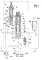
- the valve of the present invention is inserted in an activation circuit for a double-acting hydraulic actuator 100 provided with a first opening 101, through which pressurised fluid can be sent to the actuator to cause a displacement in opposition to an external load, and a second opening 102, through which pressurised fluid can be sent to the actuator to cause a displacement in agreement with the external load.
- the circuit comprises a four-way three-position distributor 103, which in the central position thereof exhibits at least a way 103a which is closed and predisposed to connect to the first opening 101 of the actuator 100.
- a first conduit 110 connects the distributor 103 to the first opening 101 of the actuator 100, while a second conduit 111 connects the distributor 103 to a valve according to the present invention.
- a safety valve 104 is connected to the closed way 103a of the distributor 103 by a branch 111a of the second conduit 111.
- the valve of the invention comprises at least a first opening 11, at least a second opening 12 and at least a third opening 13.
- the valve is connected to the closed way 103a of the distributor 103 and to the safety valve 104 at the second opening 12.
- the valve can e connected to the first opening 101 of the actuator 100, while at the third opening 13 it can be connected to the second opening 102 of the actuator 100 and the distributor 103.
- the valve further comprises a first obturator 14, mobile between at least a first position, in which it prevents a connection between the first opening 11 and the second opening 12, and at least a second position, in which is places the first opening 11 and the second opening 12 in communication.
- the first obturator 14 is provided with a pilot piston 15 solidly connected thereto which is mobile in a pilot chamber 16 by effect of a pilot pressure which pushes the first obturator from the first towards the second position.
- the pilot chamber 16 is connected to the third opening 13 of the valve, preferably through a choke 50, the function of which will be more fully explained herein below.
- Elastic means 17, preferably constituted by a calibratable helix spring, operate inside a chamber 18 and push the first obturator from the second position towards the first position, antagonistically to the action of the pilot pressure.
- the valve further comprises a second obturator 19 which is mobile between at least a first position, in which it prevents a connection between the first opening 11 and the pilot chamber 16, and at least a second position, in which it places the first opening 11 in communication with the pilot chamber 16.
- the second obturator is mobile from the first position towards the second position by effect of the thrust exerted thereon by the pressure present at the first opening 11, which pressure acts against the elastic means 20, preferably constituted by a calibratable helix spring, which push the second obturator 19 from the second position towards the first position.
- a basic aspect of the valve is constituted by the presence of a distributor 21 which alternatively places the chamber 18, in which the elastic means 17 act of the first obturator 14 act, in communication with the second opening 12 or with the third opening 13.
- the presence of the distributor 21 constitutes the main development with respect to valves of known type.
- the distributor 21 comprises a third obturator 22, mobile between at least a first position, in which it places the chamber 18 in communication with the second opening 12 of the valve, and at least a second position, in which it places the vane 18 in communication with the third opening 13 of the valve.
- the third obturator 22 comprises a first end portion provided with a pilot surface 23 which is mobile inside a pilot chamber 24 for effecting a pilot pressure which pushes the third obturator 22 from the first towards the second position, in opposition to the elastic means 25, preferably constituted by a calibratable helix spring, which elastic means 25 push the third obturator from the second towards the first position.
- the pilot chamber 24 of the third obturator 22 is in communication with the third opening 13 of the valve, preferably through a choke 50.
- the pilot chamber 16 of the first obturator 14 and the pilot chamber 24 of the third obturator 22 are in communication with the third opening 13 through the same choke 50.
- Both the pilot chambers 16, 24 can further be set in communication with the first opening 11 of the valve thanks to the second obturator 19, specifically when the second obturator 19 is in the second position thereof.
- the valve of the present invention operates as follows.
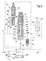
- the distributor If the distributor is now activated, bringing it into a position in which pressurised oil is supplied to the second opening 102 of the actuator 100 (figure 2), the supply of pressurised fluid to the second opening 102 causes a displacement of the actuator in the same direction as the resistant weight, in this case, for example, leading to a lowering of the weight.
- the pressurised fluid through the third opening 13 of the valve of the invention, reaches the pilot chamber 16 of the first obturator 14, which by effect of the thrust received from the pilot piston 15 moves from the first position towards the second position, placing the first opening 11 and the second opening 12 of the valve in communication.
- the pressure at the third opening 13 of the valve drops brusquely.
- the presence of the choke 50 interpositioned between the pilot chamber 16 of the first obturator 14 and the pilot chamber 24 of the third obturator 22 determines, however, a certain delay in the pressure drop within the pilot chambers 16, 24, enabling the fluid present in the actuator to discharge through the second opening 12 of the valve. Any inertiacaused pressure peaks on load arrest can be discharged via the safety valve 104 connected to the second opening 12 of the valve.
- the ready displacement of the first obturator 14 and the third obturator 22 is guaranteed by the rapid opening of the second obturator 19 which, owing to the increase of pressure at the first opening 11 of the valve, displaces from the first position towards the second position, placing the first opening 11 in communication with the pilot chambers 16, 24 of the first and third obturators.
- the elastic means 20 which act on the second obturator 19 exert a thrust on the second obturator 19 which is such that the pressure needed to determine the displacement of the second obturator 19 from the first position towards the second position is less than (or equal to) the pressure needed to cause a displacement of the first obturator 14 from the first position towards the second position.
- the chamber 18 in which the elastic means 17 of the first obturator operate is rapidly depressurised as the elastic means 25 which act on the third obturator 22 exert thereon a thrust which is such that the pressure needed to determine the displacement of the third obturator 22 from the first towards the second position is decidedly lower than the pressure needed to determine the displacement of the first obturator 14 from the first towards the second position.
- the valve preferably comprises a main body, denoted only schematically by the broken line surrounding the three obturators 14, 19, 22, internally of which the sliding seats of the various obturators are afforded, as well as the connecting conduits between the various openings of the valve and between the obturators.
- the first conduit 110 which connects the distributor 103 to the first opening 101 of the actuator 100 can be afforded partially internally of the main body of the valve.
- the first conduit 110 can be external of the main body of the valve with a connection to the third opening 13 of the valve.
- the first obturator 14 is cylindrical and comprises at least a shaped portion 14a predisposed to position strikingly against a mobile seating 27 at the first position of the first obturator 14, and a stem 14b which conjoins the shaped portion 14a to the pilot piston 15.
- the seating 27 is elastically mobile by effect of a positive pressure difference between the second opening 12 and the first opening 11 of the valve, which allows a fluid flow from the second opening 12 towards the first opening 11 of the valve.
- the shaped portion 14a is arranged between the stem 14b and an end portion 14c on which the elastic means 17 of the first obturator 14 act.
- the first obturator 14 is slidable in a seating which comprises a first tract 28, in which the pilot piston 15 of the first obturator 14 sealedly slides, which first tract delimits the pilot piston 16 of the first obturator 14.
- This second tract internally comprises the mobile seating 27, at an opposite end with respect to the first tract.
- the mobile seating 27 is constituted by a ring pushed by a spring in the direction of the shaped portion 14a of the first obturator 22.
- the tubular element 31 delimits the chamber 18 in which the elastic means 17 acting on the first obturator 14 act.
- the chamber 18 is provided with a breather opening 18a.
- At least a first opening 29a of the sliding seat of the first obturator 14 opens into the inside of the second tract 29 of the seat itself.
- the first opening 29a is connected to the first opening 11 of the valve of the invention.
- At least a second opening 30a of the sliding seat of the first obturator 14 opens into the third tract 30 of the seat and is connected to the second opening 12 of the valve.
- the presence of the mobile seat 27, as already mentioned, allows the fluid flow from the second opening 12 to the first opening 11 of the valve.
- This flow occurs when the distributor 103 is displaced into the position in which the pressurised fluid is sent to the second opening 12 of the valve in order to determine the raising of the load, or more generally a displacement of the actuator in an opposite direction to the resistant weight.
- the first obturator 14 is in the first position thereof as it does not receive any pilot pressure.
- the pressure at the second opening 12 of the valve determines the displacement of the mobile seat 27 which distances from the shaped portion 14a of the first obturator 14, enabling fluid to pass.
- the third obturator 22 is cylindrical and comprises a first end portion on which the pilot surface 23 is arranged.
- the third obturator 22 further comprises a second end portion 22a and a central portion 22b having a smaller section.
- the two end portions are slidable sealedly internally of a seat 32 which, on the side of the pilot surface 23, delimits the pilot chamber 24.
- the seat 32 of the third obturator 22 is provided with a first opening 33, connected to the second opening 12 of the valve 12, a second opening 34, connected to the breather opening 18a of the chamber 18, and a third opening 35, connected with the third opening 13 of the valve.
- the openings of the seat 32 of the third obturator 22 are positioned in such a way that when the third obturator 22 is in the first position, the first opening 33 and
- the second opening 34 at least partially face the central portion 22b of the third obturator 22 and are connected to one another, while when the third obturator 22 is in the second position the second opening 34 and the third opening 35 at least partially face the central portion 22b of the third obturator 22 and are connected to one another.
- the third obturator 22 goes into the first position thereof by effect of the thrust exerted by the elastic means 25.
- the breather opening 18a of the chamber 18 in which the elastic means 17 operating on the first obturator 14 are housed is connected to the second opening of the valve 12 through a path comprising the second opening 34, an annular chamber defined around the central portion 22b of the third obturator 22 and the first opening 33 of the seat 32.
- the third obturator 22 goes into the second position thereof.
- the breather opening 18a of the chamber 18 in which the elastic means 17 operating on the first obturator 14 are housed is connected to the third opening 13 of the valve through a path which comprises the second opening 34, the annular chamber defined around the central portion 22b of the third obturator 22 and the third opening 35 of the seat 32.
Landscapes
- Engineering & Computer Science (AREA)
- Physics & Mathematics (AREA)
- Fluid Mechanics (AREA)
- Mechanical Engineering (AREA)
- General Engineering & Computer Science (AREA)
- Safety Valves (AREA)
Priority Applications (1)
| Application Number | Priority Date | Filing Date | Title |
|---|---|---|---|
| EP06425615A EP1895169A1 (fr) | 2006-09-04 | 2006-09-04 | Ensemble de soupapes de décharge et de contrôle |
Applications Claiming Priority (1)
| Application Number | Priority Date | Filing Date | Title |
|---|---|---|---|
| EP06425615A EP1895169A1 (fr) | 2006-09-04 | 2006-09-04 | Ensemble de soupapes de décharge et de contrôle |
Publications (1)
| Publication Number | Publication Date |
|---|---|
| EP1895169A1 true EP1895169A1 (fr) | 2008-03-05 |
Family
ID=37733068
Family Applications (1)
| Application Number | Title | Priority Date | Filing Date |
|---|---|---|---|
| EP06425615A Withdrawn EP1895169A1 (fr) | 2006-09-04 | 2006-09-04 | Ensemble de soupapes de décharge et de contrôle |
Country Status (1)
| Country | Link |
|---|---|
| EP (1) | EP1895169A1 (fr) |
Cited By (2)
| Publication number | Priority date | Publication date | Assignee | Title |
|---|---|---|---|---|
| EP2317191A1 (fr) | 2009-10-29 | 2011-05-04 | Bosch Rexroth Oil Control S.p.A. | Obturateur de vanne protégé contre les fuites |
| EP2631517A1 (fr) | 2012-02-22 | 2013-08-28 | Atlantic Fluid Tech S.r.l. | Soupape à maintien de charge |
Citations (5)
| Publication number | Priority date | Publication date | Assignee | Title |
|---|---|---|---|---|
| US3304842A (en) * | 1964-04-20 | 1967-02-21 | Homer J Shafer | Non-hammer poppet valve control |
| GB2112909A (en) * | 1981-11-19 | 1983-07-27 | Komatsu Mfg Co Ltd | Hydrostatic transmission |
| EP0331076A1 (fr) * | 1988-03-03 | 1989-09-06 | KABUSHIKI KAISHA KOBE SEIKO SHO also known as Kobe Steel Ltd. | Circuit hydraulique pour cylindre |
| EP0756089A2 (fr) * | 1993-04-05 | 1997-01-29 | Deere & Company | Système hydraulique de contrÔle |
| DE102004032652A1 (de) * | 2003-09-22 | 2005-04-14 | Deere & Company, Moline | Hydraulische Federung |
-
2006
- 2006-09-04 EP EP06425615A patent/EP1895169A1/fr not_active Withdrawn
Patent Citations (5)
| Publication number | Priority date | Publication date | Assignee | Title |
|---|---|---|---|---|
| US3304842A (en) * | 1964-04-20 | 1967-02-21 | Homer J Shafer | Non-hammer poppet valve control |
| GB2112909A (en) * | 1981-11-19 | 1983-07-27 | Komatsu Mfg Co Ltd | Hydrostatic transmission |
| EP0331076A1 (fr) * | 1988-03-03 | 1989-09-06 | KABUSHIKI KAISHA KOBE SEIKO SHO also known as Kobe Steel Ltd. | Circuit hydraulique pour cylindre |
| EP0756089A2 (fr) * | 1993-04-05 | 1997-01-29 | Deere & Company | Système hydraulique de contrÔle |
| DE102004032652A1 (de) * | 2003-09-22 | 2005-04-14 | Deere & Company, Moline | Hydraulische Federung |
Cited By (3)
| Publication number | Priority date | Publication date | Assignee | Title |
|---|---|---|---|---|
| EP2317191A1 (fr) | 2009-10-29 | 2011-05-04 | Bosch Rexroth Oil Control S.p.A. | Obturateur de vanne protégé contre les fuites |
| EP2631517A1 (fr) | 2012-02-22 | 2013-08-28 | Atlantic Fluid Tech S.r.l. | Soupape à maintien de charge |
| EP2631517B1 (fr) * | 2012-02-22 | 2020-12-09 | Atlantic Fluid Tech S.r.l. | Soupape à maintien de charge |
Similar Documents
| Publication | Publication Date | Title |
|---|---|---|
| CN111828723B (zh) | 比例液压阀 | |
| KR101728842B1 (ko) | 밸브 장치 | |
| US5992449A (en) | Pilot operated safety relief valve adapted for low fluid pressures | |
| US20030172805A1 (en) | Valve device and a control cylinder | |
| US20160195879A1 (en) | Valve device | |
| JP6397715B2 (ja) | 流体圧制御装置 | |
| WO2005098297A2 (fr) | Vanne, actionneur et systeme de commande associe | |
| US8474480B1 (en) | Actuator control valve | |
| WO2016175661A1 (fr) | Actionneur hydraulique à double parallèle | |
| EP3396174A1 (fr) | Dispositif de soupape | |
| PL206052B1 (pl) | Odblokowywalny zawór zwrotny | |
| KR860001697B1 (ko) | 공압식 에너지 축적기가 달린 작동기 | |
| JP4918001B2 (ja) | 流体圧制御装置 | |
| GB2586412A (en) | Dual line hydraulic control system to operate multiple downhole valves | |
| AU2003273367B2 (en) | Hydraulic cylinder comprising a valve arrangement | |
| EP4176145B1 (fr) | Mât télescopique pneumatique | |
| MXPA01003109A (es) | Gato hidraulico impulsado por aire con control de aire de cierre automatico deteccion de carga. | |
| EP2426388B1 (fr) | Soupape à plusieurs voies précommandée | |
| EP2345815B1 (fr) | Vanne hydraulique pour supporter et contrôler la descente d'une charge | |
| US12492752B2 (en) | Movement control valve | |
| EP1251049A2 (fr) | Dispositif d'alimentation de gaz sous pression | |
| EP4603712A1 (fr) | Circuit actionné par fluide pour l'alimentation de services primaires et auxiliaires avec des priorités prédéfinies | |
| EP4001668B1 (fr) | Dispositif de commande séquentiel de deux ou plusieurs cylindres | |
| CN210600195U (zh) | 一种液动最低液面阀 | |
| KR100334340B1 (ko) | 유압제어장치 |
Legal Events
| Date | Code | Title | Description |
|---|---|---|---|
| PUAI | Public reference made under article 153(3) epc to a published international application that has entered the european phase |
Free format text: ORIGINAL CODE: 0009012 |
|
| AK | Designated contracting states |
Kind code of ref document: A1 Designated state(s): AT BE BG CH CY CZ DE DK EE ES FI FR GB GR HU IE IS IT LI LT LU LV MC NL PL PT RO SE SI SK TR |
|
| AX | Request for extension of the european patent |
Extension state: AL BA HR MK YU |
|
| AKX | Designation fees paid | ||
| REG | Reference to a national code |
Ref country code: DE Ref legal event code: 8566 |
|
| STAA | Information on the status of an ep patent application or granted ep patent |
Free format text: STATUS: THE APPLICATION IS DEEMED TO BE WITHDRAWN |
|
| 18D | Application deemed to be withdrawn |
Effective date: 20080908 |