EP1895260A2 - Kombinierter Wärmetauscher mit verbessertem Sammelkasten - Google Patents
Kombinierter Wärmetauscher mit verbessertem Sammelkasten Download PDFInfo
- Publication number
- EP1895260A2 EP1895260A2 EP07075673A EP07075673A EP1895260A2 EP 1895260 A2 EP1895260 A2 EP 1895260A2 EP 07075673 A EP07075673 A EP 07075673A EP 07075673 A EP07075673 A EP 07075673A EP 1895260 A2 EP1895260 A2 EP 1895260A2
- Authority
- EP
- European Patent Office
- Prior art keywords
- gasket
- bulkheads
- heat exchanger
- spatial distance
- end tank
- Prior art date
- Legal status (The legal status is an assumption and is not a legal conclusion. Google has not performed a legal analysis and makes no representation as to the accuracy of the status listed.)
- Granted
Links
- 239000012530 fluid Substances 0.000 claims description 20
- 239000004033 plastic Substances 0.000 claims description 15
- 229920001971 elastomer Polymers 0.000 claims description 10
- 239000000806 elastomer Substances 0.000 claims description 10
- 239000011324 bead Substances 0.000 claims description 9
- 229920001296 polysiloxane Polymers 0.000 claims description 3
- 229910052782 aluminium Inorganic materials 0.000 claims description 2
- XAGFODPZIPBFFR-UHFFFAOYSA-N aluminium Chemical compound [Al] XAGFODPZIPBFFR-UHFFFAOYSA-N 0.000 claims description 2
- 229920002379 silicone rubber Polymers 0.000 claims 1
- 230000006835 compression Effects 0.000 abstract description 31
- 238000007906 compression Methods 0.000 abstract description 31
- 239000013529 heat transfer fluid Substances 0.000 description 8
- 229910052751 metal Inorganic materials 0.000 description 8
- 239000002184 metal Substances 0.000 description 8
- 238000005192 partition Methods 0.000 description 5
- 238000005219 brazing Methods 0.000 description 4
- 238000004891 communication Methods 0.000 description 4
- LYCAIKOWRPUZTN-UHFFFAOYSA-N Ethylene glycol Chemical compound OCCO LYCAIKOWRPUZTN-UHFFFAOYSA-N 0.000 description 3
- 239000012080 ambient air Substances 0.000 description 3
- 230000004888 barrier function Effects 0.000 description 3
- 238000002485 combustion reaction Methods 0.000 description 3
- 238000005476 soldering Methods 0.000 description 3
- 238000003466 welding Methods 0.000 description 3
- 238000001514 detection method Methods 0.000 description 2
- 238000009826 distribution Methods 0.000 description 2
- 230000017525 heat dissipation Effects 0.000 description 2
- 238000002955 isolation Methods 0.000 description 2
- 230000003014 reinforcing effect Effects 0.000 description 2
- 239000004677 Nylon Substances 0.000 description 1
- 238000009825 accumulation Methods 0.000 description 1
- 239000003570 air Substances 0.000 description 1
- 230000005540 biological transmission Effects 0.000 description 1
- 238000010276 construction Methods 0.000 description 1
- 238000007599 discharging Methods 0.000 description 1
- 238000001746 injection moulding Methods 0.000 description 1
- 238000004519 manufacturing process Methods 0.000 description 1
- 239000000463 material Substances 0.000 description 1
- 238000000034 method Methods 0.000 description 1
- 239000000203 mixture Substances 0.000 description 1
- 229920001778 nylon Polymers 0.000 description 1
- 238000004806 packaging method and process Methods 0.000 description 1
- 230000002787 reinforcement Effects 0.000 description 1
- 238000000638 solvent extraction Methods 0.000 description 1
- XLYOFNOQVPJJNP-UHFFFAOYSA-N water Substances O XLYOFNOQVPJJNP-UHFFFAOYSA-N 0.000 description 1
Images


Classifications
-
- F—MECHANICAL ENGINEERING; LIGHTING; HEATING; WEAPONS; BLASTING
- F28—HEAT EXCHANGE IN GENERAL
- F28F—DETAILS OF HEAT-EXCHANGE AND HEAT-TRANSFER APPARATUS, OF GENERAL APPLICATION
- F28F9/00—Casings; Header boxes; Auxiliary supports for elements; Auxiliary members within casings
- F28F9/02—Header boxes; End plates
- F28F9/0219—Arrangements for sealing end plates into casing or header box; Header box sub-elements
- F28F9/0224—Header boxes formed by sealing end plates into covers
- F28F9/0226—Header boxes formed by sealing end plates into covers with resilient gaskets
-
- F—MECHANICAL ENGINEERING; LIGHTING; HEATING; WEAPONS; BLASTING
- F28—HEAT EXCHANGE IN GENERAL
- F28D—HEAT-EXCHANGE APPARATUS, NOT PROVIDED FOR IN ANOTHER SUBCLASS, IN WHICH THE HEAT-EXCHANGE MEDIA DO NOT COME INTO DIRECT CONTACT
- F28D1/00—Heat-exchange apparatus having stationary conduit assemblies for one heat-exchange medium only, the media being in contact with different sides of the conduit wall, in which the other heat-exchange medium is a large body of fluid, e.g. domestic or motor car radiators
- F28D1/02—Heat-exchange apparatus having stationary conduit assemblies for one heat-exchange medium only, the media being in contact with different sides of the conduit wall, in which the other heat-exchange medium is a large body of fluid, e.g. domestic or motor car radiators with heat-exchange conduits immersed in the body of fluid
- F28D1/04—Heat-exchange apparatus having stationary conduit assemblies for one heat-exchange medium only, the media being in contact with different sides of the conduit wall, in which the other heat-exchange medium is a large body of fluid, e.g. domestic or motor car radiators with heat-exchange conduits immersed in the body of fluid with tubular conduits
- F28D1/0408—Multi-circuit heat exchangers, e.g. integrating different heat exchange sections in the same unit or heat exchangers for more than two fluids
- F28D1/0426—Multi-circuit heat exchangers, e.g. integrating different heat exchange sections in the same unit or heat exchangers for more than two fluids with units having particular arrangement relative to the large body of fluid, e.g. with interleaved units or with adjacent heat exchange units in common air flow or with units extending at an angle to each other or with units arranged around a central element
- F28D1/0443—Combination of units extending one beside or one above the other
-
- F—MECHANICAL ENGINEERING; LIGHTING; HEATING; WEAPONS; BLASTING
- F28—HEAT EXCHANGE IN GENERAL
- F28F—DETAILS OF HEAT-EXCHANGE AND HEAT-TRANSFER APPARATUS, OF GENERAL APPLICATION
- F28F9/00—Casings; Header boxes; Auxiliary supports for elements; Auxiliary members within casings
- F28F9/02—Header boxes; End plates
- F28F9/0202—Header boxes having their inner space divided by partitions
- F28F9/0204—Header boxes having their inner space divided by partitions for elongated header box, e.g. with transversal and longitudinal partitions
- F28F9/0209—Header boxes having their inner space divided by partitions for elongated header box, e.g. with transversal and longitudinal partitions having only transversal partitions
-
- F—MECHANICAL ENGINEERING; LIGHTING; HEATING; WEAPONS; BLASTING
- F28—HEAT EXCHANGE IN GENERAL
- F28F—DETAILS OF HEAT-EXCHANGE AND HEAT-TRANSFER APPARATUS, OF GENERAL APPLICATION
- F28F2270/00—Thermal insulation; Thermal decoupling
- F28F2270/02—Thermal insulation; Thermal decoupling by using blind conduits
Definitions
- the invention relates to a combination heat exchanger, for a motor vehicle, having an end tank assembly that includes an integrated plastic tank mated to a metal header with an improved gasket therebetween; more particularly, where the improved gasket is formed of cure-in-place elastomer having varying compression ratios.
- radiators are commonly used in automobiles having an internal combustion engine to convey heat away from hot engine components to the cooler ambient air.
- a radiator is part of a closed loop system wherein the radiator is hydraulically connected to passageways within an engine through which a heat transfer fluid, such as a mixture of water and ethylene glycol, is circulated.
- a typical radiator is formed of a central core having a multitude of parallel tubes with fins therebetween to increase the surface area for optimal heat dissipation. Hydraulically attached to either end of the core that corresponds with the tube openings is an end tank. After absorbing heat from a heat source, the heat transfer fluid enters a first end tank where the fluid flow is uniformly distributed through the parallel tubes. As the fluid flows through the parallel tubes to the second end tank, heat is radiated to the ambient air. To assist in the heat transfer, a stream of ambient air is blown perpendicularly relative to the radiator core through the fins. The cooled heat transfer fluid then exits the second end tank returning to the heat source to repeat the heat transfer process.
- Some motor vehicles have multiple radiators to cool a plurality of heat sources such as an internal combustion engine, transmission, electronic components, and charge air coolers.
- the multiple radiators are stacked.
- a major draw back of stacking radiators is a decrease of heat transfer efficiency due to the increased pressure drop through the stack of radiators.
- There are other drawbacks of utilizing multiple radiators such as increase in vehicle weight, systems complexity, and manufacturing cost.
- the combination radiator includes a single core 10 assembled from multiple of parallel tubes 20. Longitudinally attached to either end of core 10 corresponding to the tube openings 3 5 a, 35b, is an end tank 30a, 30b, respectively. Each end tank 30a, 30b has a transverse partition 40a, 40b, respectively partitioning the end tanks into compartments 50a, 50b, 60a, and 60b. Each of the end tanks is typically of metal construction with stamped openings 70 on a side wall 15 to accommodate the tubes openings 35.
- the tubes 20 are typically affixed to the side wall 15 of the end tanks by brazing or welding thereby effectively segregating the core 10 into a first core portion 80 and a second core portion 85.
- the first heat transfer fluid from the first heat source enters the first inlet 90a to compartment 50a, travels through tubes 20 to compartment 50b, and then exits first outlet 90b returning to the first heat source.
- the second heat transfer fluid from the second heat source enters the second inlet 95a to compartment 60a, travels through tubes 20 to compartment 60b, and exits second outlet 95b returning to the second heat source.
- the two heat transfer fluids are cooled by the same airflow which sweeps through core 10.
- transverse partitions 40a, 40b Utilizing a combination radiator to dissipate heat from multiple heat transfer fluids having different thermal and pressure cycle requirements may result in failure of structural integrity in transverse partitions 40a, 40b.
- the expansion differential between compartments 50a, 60a of an end tank 30a caused by the difference in temperature and pressure of the respective heat transfer fluids increases the stress on transverse partition 40a. Due to excessive stress, transverse partition 40a may fail thereby allowing the heat transfer fluids to intermingle resulting in potential damage to the heat sources being cooled.
- transverse partitions 40a, 40b does not offer a significant thermal barrier between the two different heat transfer fluids thereby resulting in decrease efficiency of heat dissipation of the cooler heat source.
- the invention relates to a combination heat exchanger, for a motor vehicle with an internal combustion engine, having an end tank assembly that includes a single piece integrated plastic tank mated to a metal header with an improved gasket therebetween. More particularly, the improved gasket is formed of cure-in-place elastomer, preferably silicone, having varying compression ratios.
- the combination heat exchanger includes a heat exchange core having a bundle of tubes that are substantially parallel.
- the tubes are joint together longitudinally with heat dissipating fins.
- the core has two core ends, where each of the core ends is attached to an end tank assembly.
- the end tank assembly includes a one piece integrated plastic tank, wherein the tank has two side walls connected to a bottom wall along a longitudinal axis, and two end walls along a latitudinal axis defining an elongated cavity. The exterior edges of the side walls and end walls define a perimeter edge. Within the elongated cavity are two bulkheads situated along a latitudinal axis dividing the elongated cavity into a first chamber, a second chamber, and a third chamber. Reinforcing the two bulkheads is a rib buttressing the two bulkheads with the bottom wall.
- a metal header plate preferably aluminum, engaged between each of the end tanks and core ends.
- the header plate has stamped perforations to accommodate the tubes openings.
- the tubes are attached to the header plate by conventional means such as brazing or soldering.
- the header plate is then mated to the plastic tank by mechanical means with a gasket therebetween.
- an elastomer gasket preferably silicone.
- the gasket is applied on the perimeter edge of the end tank and exterior edges of the bulk heads, and then cured-in-place before the end tank is mated to the header plate by mechanical means.
- the header plate has a stage portion with latitudinal pockets to cooperate with the exterior edges of the bulkheads to define a first spatial distance with respect to the gasket therein.
- the header plate also has an annular planar surface to cooperate with the perimeter edge of the end tank to define a second spatial distance with respect to the gasket therein.
- the first spatial distance is less than the second spatial distance, thereby resulting in a greater compression ratio of the gasket located within the first spatial distance relative to the compression ratio of the gasket located within the second spatial distance. More specifically, the compression ratio of the gasket on the exterior edges of the bulkhead is greater than the compression ratio of the gasket on the perimeter edge of the end tank.
- the greater compression ratio of the gasket between the exterior edges of the bulkheads and lateral pockets of the header plate allows for a more robust seal between chambers. Robust seals are required along bulkheads to withstand stresses resulting from expansion differential between chambers within an end tank of a combination heat exchanger that houses heat transfer fluids with different temperature and pressure cycle requirements.
- Fig. 1 is a cross-sectional view of a prior art combination heat exchanger.
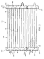
- Fig. 2 is a cross-section view of the present invention combination heat exchanger having an end tank assembly that includes an integrated end tank, a header plate, and a gasket therebetween.
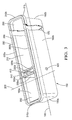
- Fig. 3 is a perspective view of an integrated plastic end tank having two bulk heads, reinforcement rib, and means for leak detection with gasket applied on perimeter edge.
- Fig. 4 is a partial perspective view of an alternative embodiment of an integrated plastic end tank having a foot step with gasket applied on perimeter edge in relationship to a metal header prior to assembly.
- Fig. 5 is a partial cross sectional view taken along the longitudinal axis of an integrated plastic end tank with gasket applied on perimeter edge in relationship to a metal header prior to assembly.
- Fig. 6 is a partial cross sectional view taken along the longitudinal axis of an integrated plastic end tank with gasket in relationship to a metal header after assembly.
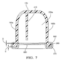
- Fig. 7 is a cross sectional view of an integrated plastic end tank along latitudinal axis between bulkheads in relationship to a metal header after assembly.
- Fig. 8 is a top view of an integrated plastic tank with gasket applied showing difference in gasket compression ratio along perimeter edge.
- end tank 150 is shown substantially rectangular in appearance.
- the present invention does not intend the substantially rectangular shape to be limiting, but can also encompass other elongated shapes with an open face along the longitudinal axis.
- Fig. 2 is a cross-sectional view of the present invention combination heat exchanger.
- the heat exchanger includes a core 110 having a bundle of tubes 120 that are substantially parallel.
- the tubes 120 are jointed longitudinally by conventional means such as welding, brazing or soldering to a supporting structure such as fins between the tubes.
- the core 110 has two core ends 140a, 140b corresponding with tube openings 145.
- Each core end is attached to end tank assembly 105 that comprises of end tank 150, a gasket 280, and a header plate 270.
- the tube openings 145 are affixed to perforations 620 located on the header plate 270 by conventional means such as welding, brazing or soldering.
- Header plate 270 is mechanically attached to end tank 150 with gasket 280 between the contact surfaces of header plate 270 and end tank 150.
- end tank 150 has two side walls 160a, 160b that are integral with a bottom wall 170 along a longitudinal axis 180 and two end walls 190a, 190b along a latitudinal axis 200 defining an elongated cavity 210.
- the tank opening is defined by a perimeter tank foot 215 that protrudes laterally outward from the exterior edges of the two side walls 300a, 300b and exterior edges of the two end walls 310a, 310b.
- the elongated cavity 210 Within the elongated cavity 210 are two bulkheads 220a, 220b situated along a latitudinal axis 200 dividing the elongated cavity 210 into a first chamber 230, a second chamber 240, and a third chamber 250.
- the heights of the bulkheads are less that heights of the side and end walls. Height of bulkhead is show as distance A and heights of walls are show as distance B in Fig. 5.
- the volume distribution for each chamber which is dictated by the number tubes 120 required to be in communication with each of the three chambers for the desired heat transfer requirements, can be adjusted by varying the placement of the bulkheads 220a, 220b along the longitudinal axis 180.
- the first chamber 230 and third chamber 250 are utilized for accumulation of heat transfer fluid and distribution of flow across the tubes 120.
- the second chamber 240 situated between the first chamber 230 and third chamber 250 is empty and acts as a thermal barrier to isolate the temperature and pressure variations between the first chamber 230 and third chamber 250.
- Tubes 120 in communication with the second chamber are dead, voided of fluid flow, thereby providing a thermal barrier between tubes in communication with first chamber 230 and tubes in communication with third chamber 250.
- Rib 410 integrally connecting bulkheads 220a, 220b with bottom wall 170. Rib 410 is located along the longitudinal axis 180 in the second chamber 240.
- a mean to detect leaks from first chamber 230 and third chamber 250 into the second chamber 240 is also located within second chamber 240.
- the means can include a mechanical or electrical sensing device; however, the preferred mean is an outlet 420 on a side walls between the bulkheads. A breach in integrity of either one of the bulkheads will result in heat transfer fluid filling second chamber 240 and then discharging through outlet 420.
- the direct discharge of the heat transfer fluid from either one of the bulkheads prevents intermingling of heat exchanger fluids and allows for economical leak detection since no additional hardware is required.
- End tank 150 having bulkheads 220a, 220b, rib 410, and outlet 420 is formed of plastic, preferably nylon, and it is a seamless integrated one piece unit. End tank 150 can be manufactured by conventional means such plastic injection molding.
- the exterior edges of the two side walls 300a, 300b, and exterior edges of the two end walls 210a, 210b, together with the protruding perimeter foot 500 forms a perimeter edge.
- a uniform bead of elastomer gasket 280 is applied on perimeter edge 260 and exterior edges of the two bulkheads 320a, 320b. The gasket is then cured-in-place prior to assembling end tank 150 to header plate 270.
- a bead of elastomer gasket is applied on the perimeter edge portion that outlines the first chamber 230 with the gasket knit line 500 overlapping on exterior edge of bulk head 320b defining first chamber 230.
- Another uniform bead of gasket is applied on the perimeter edge portion that outlines the third chamber with the gasket knit line 500 overlapping on exterior edge of bulk head 320a defining the third chamber 250.
- the knit lines 500 of the gaskets it is desirable for the knit lines 500 of the gaskets to overlap on the exterior edges of the bulkheads 320a, 320b.
- the overlapping of the knit lines 500 provides additional gasket material to allow for greater compression ratio of the gasket on the edges of the bulk heads 320a, 320b.
- the higher compression ratio of the gasket provides greater seal integrity between the bulkheads with the header plate 270. It is optional to provide gasket on the portion of the perimeter edge that is part of the side wall of the second chamber located between the bulk heads.
- the Compression Ratio of the gasket is defined as the ratio between the Compression Squeeze and the original cross-section of the gasket.
- the compression ratio is typically expressed as a percentage.
- Compression Squeeze original cross section - compressed cross section
- Compression Ration (%) (compression squeeze/original cross section) x 100
- the physical feature of the header plate 270 includes a stage portion 600 that is elevated toward elongated cavity 210 of end tank 150.
- Stage portion 600 includes latitudinal pockets 610 to cooperate with the exterior edges of the bulkheads 320a, 320b to define a first spatial distance X shown in Fig. 6.
- the header plate also has an annular planar surface that circumscribes stage portion 600, to cooperate with the perimeter edge of the end tank to define a second spatial distance Y shown in Fig. 6.
- the original cross section or diameter of the gasket is shown as distance Z in Fig. 5 which is greater than distance Y and distance X.
- the first spatial distance X is less than the second spatial distance Y, thereby resulting in a greater compression ratio of the gasket located within the first spatial distance relative to the compression ratio of the gasket located within the second spatial distance. More specifically, the compression ratio of the gasket on the exterior edges of the bulkhead is greater than the compression ratio of the gasket on the perimeter edge of the end tank as shown in Fig. 7.
- the greater compression ratio of the gasket between the exterior edges of the bulkheads and lateral pockets of the header plate allows for a more robust seal between chambers. Robust seals are required along bulkheads to withstand expansion differential stresses associated with combination heat exchanger that houses heat transfer fluids with different temperature and pressure cycle requirements.
- header plate 270 periodically protruding outward of header plate 270 are crimp tabs 640.
- crimp taps 640 are plastically deformed to embrace the perimeter tank foot 215 of end tank 150.
- the latitudinal pockets 610 and annular planar surface 630 acts as the contact surface to the cure-in-place gasket which is applied on the perimeter edge of the end tank and exterior edge of bulkheads 220a, 220b.
- FIG. 4 Shown in Fig. 4 is another embodiment of the invention wherein a tank foot step 400 is located on the edges of the two side wall located between the bulkheads 220a, 220b in surrogate of a segment of gasket.
- the tank foot step 400 provides a secure seal against the contact surface of the header plate 290 while maintaining proper compression ratio of the gasket located along the exterior edges of the bulkheads 320a, 320b.
- the compression ratio of the gasket along said exterior edges of said two side wall and along said exterior edges of said two end walls is represented as M%, where as the compression ratio of the gasket along exterior edges of said bulkheads is represented as M% + N%.
- the compression ratio of the gasket along said exterior edges of said two side wall and along said exterior edges of said two end walls is between 40 to 60 percent, preferably 50 percent, and the compression ratio of the gasket along exterior edges of said bulkheads is between 50 and 70 percent, preferably 60 percent.
- the compression ratio of the gasket along the exterior edges of the bulkheads is determined by the spatial distance between the bulkheads and the latitudinal pockets of the header plate, shown as distance X in Fig. 6 and Fig. 7.
- the compression ratio of the gasket along the exterior edges of the perimeter edge is determined by the spatial distance between the perimeter edge and annular planar surface of the header plate, shown as distance Y in Fig. 6 and Fig. 7.
Landscapes
- Engineering & Computer Science (AREA)
- Physics & Mathematics (AREA)
- Thermal Sciences (AREA)
- Mechanical Engineering (AREA)
- General Engineering & Computer Science (AREA)
- Heat-Exchange Devices With Radiators And Conduit Assemblies (AREA)
Applications Claiming Priority (1)
| Application Number | Priority Date | Filing Date | Title |
|---|---|---|---|
| US11/507,804 US7779893B2 (en) | 2006-08-22 | 2006-08-22 | Combination heat exchanger having an improved end tank assembly |
Publications (3)
| Publication Number | Publication Date |
|---|---|
| EP1895260A2 true EP1895260A2 (de) | 2008-03-05 |
| EP1895260A3 EP1895260A3 (de) | 2010-06-02 |
| EP1895260B1 EP1895260B1 (de) | 2012-04-11 |
Family
ID=38780782
Family Applications (1)
| Application Number | Title | Priority Date | Filing Date |
|---|---|---|---|
| EP07075673A Not-in-force EP1895260B1 (de) | 2006-08-22 | 2007-08-13 | Sammelkasten and Kombinierter Wärmetauscher |
Country Status (3)
| Country | Link |
|---|---|
| US (1) | US7779893B2 (de) |
| EP (1) | EP1895260B1 (de) |
| AT (1) | ATE553350T1 (de) |
Cited By (4)
| Publication number | Priority date | Publication date | Assignee | Title |
|---|---|---|---|---|
| CN102052872A (zh) * | 2009-11-06 | 2011-05-11 | 株式会社电装 | 热交换器 |
| EP2317265A3 (de) * | 2009-10-29 | 2015-03-11 | Behr GmbH & Co. KG | Wärmetauscher, insbesondere Kühlmittelkühler für ein Kraftfahrzeug, mit zwei Tauscherabschnitten, insbesondere einem Niedertemperatur- und einem Hochtemperaturabschnitt |
| WO2015096956A1 (de) * | 2013-12-23 | 2015-07-02 | MAHLE Behr GmbH & Co. KG | Wärmetauscher mit umlaufender dichtung |
| EP3246646A1 (de) * | 2016-05-20 | 2017-11-22 | Valeo Systemes Thermiques | Kühler, insbesondere gaskühler eines kühlsystems |
Families Citing this family (30)
| Publication number | Priority date | Publication date | Assignee | Title |
|---|---|---|---|---|
| WO2007079140A2 (en) * | 2005-12-28 | 2007-07-12 | Wabtec Holding Corp. | Multi-fluid heat exchanger arrangement |
| US20080053645A1 (en) * | 2006-08-31 | 2008-03-06 | Denso Corporation | Heat exchanger and manufacture method for the same |
| US9328966B2 (en) * | 2007-11-01 | 2016-05-03 | Modine Manufacturing Company | Heat exchanger with a baffle reinforcement member |
| FR2927411B1 (fr) * | 2008-02-13 | 2013-03-29 | Valeo Systemes Thermiques | Moyens d'etancheite pour une boite collectrice d'echangeur de chaleur |
| FR2930632B1 (fr) * | 2008-04-28 | 2010-05-07 | Air Liquide | Procede de reparation d'un echangeur de chaleur a plaques |
| KR20100023600A (ko) * | 2008-08-22 | 2010-03-04 | 현대자동차주식회사 | 자동차의 라디에이터 |
| CN101362452A (zh) * | 2008-09-05 | 2009-02-11 | 无锡优萌汽车部件制造有限公司 | 新型汽车散热器的水室与主片之连接结构 |
| KR101013873B1 (ko) * | 2008-11-10 | 2011-02-14 | 현대자동차주식회사 | 수두차를 이용한 통합형 하이브리드 열교환기 |
| US20110073291A1 (en) * | 2009-09-30 | 2011-03-31 | Zaiqian Hu | Cooling module for a vehicle |
| JP5585456B2 (ja) | 2011-01-06 | 2014-09-10 | 株式会社デンソー | 熱交換器およびその製造方法 |
| DE102011005168A1 (de) * | 2011-03-07 | 2012-09-13 | Behr Gmbh & Co. Kg | Wärmetauscher und Verfahren zur Herstellung eines Wärmetauschers |
| JP5541218B2 (ja) * | 2011-04-01 | 2014-07-09 | 株式会社デンソー | 熱交換器 |
| KR101372096B1 (ko) * | 2011-11-18 | 2014-03-07 | 엘지전자 주식회사 | 열교환기 |
| DE102011089091A1 (de) * | 2011-12-19 | 2013-06-20 | Behr Gmbh & Co. Kg | Wärmeübertrager |
| KR20140006681A (ko) * | 2012-07-06 | 2014-01-16 | 삼성전자주식회사 | 열교환기 및 그 제조 방법 |
| KR102025738B1 (ko) * | 2012-07-06 | 2019-09-27 | 삼성전자주식회사 | 냉장고 및 이에 구비되는 열교환기 |
| CN103711561B (zh) | 2012-10-02 | 2018-11-02 | 马勒国际公司 | 热交换器 |
| US9829252B2 (en) | 2013-10-04 | 2017-11-28 | Denso International America, Inc. | Tank for heat exchanger |
| US10030918B2 (en) * | 2014-10-09 | 2018-07-24 | Enterex America LLC | Radiator tank fastening system |
| JP6308115B2 (ja) * | 2014-11-28 | 2018-04-11 | 株式会社デンソー | 熱交換器 |
| KR101646129B1 (ko) * | 2015-02-16 | 2016-08-05 | 현대자동차 주식회사 | 차량용 라디에이터 |
| JP6513427B2 (ja) * | 2015-02-27 | 2019-05-15 | 昭和電工株式会社 | 液冷式冷却装置 |
| US9763388B2 (en) | 2015-09-15 | 2017-09-19 | Cnh Industrial America Llc | Agricultural harvester having a header based heat exchanger |
| US20170328637A1 (en) * | 2016-05-13 | 2017-11-16 | Denso Thermal Systems S.P.A. | Heat exchanger with dummy tubes |
| JP2018146216A (ja) * | 2017-03-09 | 2018-09-20 | 株式会社ティラド | 複数流路熱交換器 |
| CN115420134B (zh) * | 2017-09-15 | 2024-10-01 | 翰昂汽车零部件有限公司 | 一体式热交换器 |
| KR102430786B1 (ko) * | 2017-12-19 | 2022-08-10 | 한온시스템 주식회사 | 일체형 열교환기 |
| JP7025270B2 (ja) * | 2018-04-06 | 2022-02-24 | ダイキン工業株式会社 | 熱交換器及びそれを備えた熱交換ユニット |
| KR102533346B1 (ko) * | 2018-08-20 | 2023-05-19 | 한온시스템 주식회사 | 일체형 열교환기 |
| US12305939B2 (en) * | 2020-02-19 | 2025-05-20 | Hanon Systems | Heat exchanger having flow distribution tank structure for thermal stress dispersion |
Family Cites Families (17)
| Publication number | Priority date | Publication date | Assignee | Title |
|---|---|---|---|---|
| US2037845A (en) * | 1935-08-12 | 1936-04-21 | Young Radiator Co | Radiator |
| DE3341361C2 (de) * | 1983-02-07 | 1986-12-04 | Industria Piemontese Radiatori Automobili S.p.A. IPRA, Pianezza, Turin/Torino | Radiator, insbesondere für Klimaanlagen von Kraftfahrzeugen |
| US4781320A (en) * | 1987-04-27 | 1988-11-01 | Nihon Radiator Co., Ltd. | Method for the production of a heat exchanger |
| US4817967A (en) * | 1987-12-11 | 1989-04-04 | Dana Corporation | Angled junction sealing structure for gaskets |
| US4926934A (en) * | 1989-05-22 | 1990-05-22 | Ivy Eugene S | Radiator tank plates |
| US5031924A (en) * | 1989-11-30 | 1991-07-16 | Blackstone Corporation | Twist indicator gasket |
| FR2690229A1 (fr) * | 1992-04-21 | 1993-10-22 | Valeo Thermique Moteur Sa | Echangeur de chaleur du type comprenant un faisceau de tubes à ailettes et un ensemble collecteur-boîte à eau. |
| US5195581A (en) * | 1992-05-15 | 1993-03-23 | General Motors Corporation | Snap on radiator tank |
| DE4232376C2 (de) * | 1992-09-26 | 1997-09-11 | Behr Gmbh & Co | Wärmetauscher |
| FR2781280B1 (fr) * | 1998-07-17 | 2000-09-22 | Valeo Climatisation | Ensemble boite a fluide-collecteur pour echangeur de chaleur, en particulier de vehicule automobile |
| FR2785376B1 (fr) * | 1998-10-29 | 2001-01-12 | Valeo Thermique Moteur Sa | Echangeur de chaleur multifonction, notamment pour vehicule automobile |
| FR2786259B1 (fr) * | 1998-11-20 | 2001-02-02 | Valeo Thermique Moteur Sa | Echangeur de chaleur combine, en particulier pour vehicule automobile |
| US6938675B2 (en) * | 2000-10-11 | 2005-09-06 | Denso Corporation | Heat exchanger |
| US6883600B2 (en) * | 2002-05-16 | 2005-04-26 | Denso Corporation | Heat exchanger with dual heat-exchanging portions |
| US6722660B2 (en) * | 2002-06-27 | 2004-04-20 | Federal-Mogul World Wide, Inc. | Molded gasket |
| AU2003250891A1 (en) * | 2002-07-05 | 2004-01-23 | Behr Gmbh And Co. Kg | Heat exchanger in particular an evaporator for a vehicle air-conditioning unit |
| JP2004340485A (ja) * | 2003-05-15 | 2004-12-02 | Calsonic Kansei Corp | 複合型熱交換器 |
-
2006
- 2006-08-22 US US11/507,804 patent/US7779893B2/en not_active Expired - Fee Related
-
2007
- 2007-08-13 EP EP07075673A patent/EP1895260B1/de not_active Not-in-force
- 2007-08-13 AT AT07075673T patent/ATE553350T1/de active
Non-Patent Citations (1)
| Title |
|---|
| None |
Cited By (7)
| Publication number | Priority date | Publication date | Assignee | Title |
|---|---|---|---|---|
| EP2317265A3 (de) * | 2009-10-29 | 2015-03-11 | Behr GmbH & Co. KG | Wärmetauscher, insbesondere Kühlmittelkühler für ein Kraftfahrzeug, mit zwei Tauscherabschnitten, insbesondere einem Niedertemperatur- und einem Hochtemperaturabschnitt |
| CN102052872A (zh) * | 2009-11-06 | 2011-05-11 | 株式会社电装 | 热交换器 |
| CN102052872B (zh) * | 2009-11-06 | 2013-07-31 | 株式会社电装 | 热交换器 |
| US8944154B2 (en) | 2009-11-06 | 2015-02-03 | Denso Corporation | Heat exchanger |
| WO2015096956A1 (de) * | 2013-12-23 | 2015-07-02 | MAHLE Behr GmbH & Co. KG | Wärmetauscher mit umlaufender dichtung |
| US10436526B2 (en) | 2013-12-23 | 2019-10-08 | MAHLE Behr GmbH & Co. KG | Heat exchanger with a circumferential seal |
| EP3246646A1 (de) * | 2016-05-20 | 2017-11-22 | Valeo Systemes Thermiques | Kühler, insbesondere gaskühler eines kühlsystems |
Also Published As
| Publication number | Publication date |
|---|---|
| EP1895260A3 (de) | 2010-06-02 |
| US20080047687A1 (en) | 2008-02-28 |
| ATE553350T1 (de) | 2012-04-15 |
| US7779893B2 (en) | 2010-08-24 |
| EP1895260B1 (de) | 2012-04-11 |
Similar Documents
| Publication | Publication Date | Title |
|---|---|---|
| EP1895260B1 (de) | Sammelkasten and Kombinierter Wärmetauscher | |
| US8910704B2 (en) | Heat exchanger | |
| US6082439A (en) | Heat exchanger assembled without brazing in which adhesive is used to seal a combined portion and a core plate | |
| CN102459839B (zh) | 集成有增压空气冷却器的吸管 | |
| US8695574B2 (en) | Intake manifold having an integrated charge air cooler | |
| CN102109254B (zh) | 带蓄冷功能的蒸发器 | |
| AU754417B2 (en) | Welded heat exchanger with grommet construction | |
| CN103314195B (zh) | 具有集成式中间冷却器的进气管 | |
| JP2011099631A (ja) | 熱交換器 | |
| US10955197B2 (en) | Structurally integral heat exchanger within a plastic housing | |
| US20080000627A1 (en) | Heat exchanger | |
| US20110168364A1 (en) | Heat exchanger | |
| US20090151918A1 (en) | Heat Exchanger for Automobile and Fabricating Method Thereof | |
| CN108826759A (zh) | 带蓄冷功能的蒸发器 | |
| US10378834B2 (en) | Tube header for heat exchanger | |
| US20080185136A1 (en) | Heat exchanger with bypass seal | |
| US6321832B1 (en) | Radiator with integrated liquid-air hybrid oil cooler | |
| US20070079957A1 (en) | Heat exchanger | |
| US6953080B2 (en) | Front end structure of vehicle preventing short-circuit of cooling air | |
| US20080105415A1 (en) | Chamber For Holding A Fluid For A Heat Exchanger, Heat Exchanger, More Particularly For A Heat Exchange Unit, And A Heat Exchange Unit, In Particular In The Form Of A Monoblock | |
| EP3739284A1 (de) | Hybrider wärmetauscher | |
| US20100230080A1 (en) | Tank structure of heat exchanger | |
| US20250389498A1 (en) | Integrated heat exchanger | |
| US20070256818A1 (en) | Tank structure of heat exchanger and method for manufacturing the same | |
| KR20070073175A (ko) | 축냉 열교환기 |
Legal Events
| Date | Code | Title | Description |
|---|---|---|---|
| PUAI | Public reference made under article 153(3) epc to a published international application that has entered the european phase |
Free format text: ORIGINAL CODE: 0009012 |
|
| AK | Designated contracting states |
Kind code of ref document: A2 Designated state(s): AT BE BG CH CY CZ DE DK EE ES FI FR GB GR HU IE IS IT LI LT LU LV MC MT NL PL PT RO SE SI SK TR |
|
| AX | Request for extension of the european patent |
Extension state: AL BA HR MK YU |
|
| PUAL | Search report despatched |
Free format text: ORIGINAL CODE: 0009013 |
|
| AK | Designated contracting states |
Kind code of ref document: A3 Designated state(s): AT BE BG CH CY CZ DE DK EE ES FI FR GB GR HU IE IS IT LI LT LU LV MC MT NL PL PT RO SE SI SK TR |
|
| AX | Request for extension of the european patent |
Extension state: AL BA HR MK RS |
|
| RIC1 | Information provided on ipc code assigned before grant |
Ipc: F28D 1/04 20060101ALI20100423BHEP Ipc: F28F 9/02 20060101AFI20071213BHEP |
|
| 17P | Request for examination filed |
Effective date: 20101202 |
|
| AKX | Designation fees paid |
Designated state(s): AT BE BG CH CY CZ DE DK EE ES FI FR GB GR HU IE IS IT LI LT LU LV MC MT NL PL PT RO SE SI SK TR |
|
| RIC1 | Information provided on ipc code assigned before grant |
Ipc: F28F 9/02 20060101AFI20110930BHEP Ipc: F28D 1/04 20060101ALI20110930BHEP |
|
| RTI1 | Title (correction) |
Free format text: END TANK ASSEMBLY AND COMBINATION HEAT EXCHANGER |
|
| GRAP | Despatch of communication of intention to grant a patent |
Free format text: ORIGINAL CODE: EPIDOSNIGR1 |
|
| GRAS | Grant fee paid |
Free format text: ORIGINAL CODE: EPIDOSNIGR3 |
|
| GRAA | (expected) grant |
Free format text: ORIGINAL CODE: 0009210 |
|
| AK | Designated contracting states |
Kind code of ref document: B1 Designated state(s): AT BE BG CH CY CZ DE DK EE ES FI FR GB GR HU IE IS IT LI LT LU LV MC MT NL PL PT RO SE SI SK TR |
|
| REG | Reference to a national code |
Ref country code: GB Ref legal event code: FG4D |
|
| REG | Reference to a national code |
Ref country code: CH Ref legal event code: EP |
|
| REG | Reference to a national code |
Ref country code: AT Ref legal event code: REF Ref document number: 553350 Country of ref document: AT Kind code of ref document: T Effective date: 20120415 |
|
| REG | Reference to a national code |
Ref country code: IE Ref legal event code: FG4D |
|
| RIN2 | Information on inventor provided after grant (corrected) |
Inventor name: COYLE, BRIAN J. Inventor name: LEITCH, FRANK J. Inventor name: GMEREK, ROBERT C. |
|
| REG | Reference to a national code |
Ref country code: DE Ref legal event code: R096 Ref document number: 602007021835 Country of ref document: DE Effective date: 20120606 |
|
| REG | Reference to a national code |
Ref country code: NL Ref legal event code: VDEP Effective date: 20120411 |
|
| REG | Reference to a national code |
Ref country code: AT Ref legal event code: MK05 Ref document number: 553350 Country of ref document: AT Kind code of ref document: T Effective date: 20120411 |
|
| LTIE | Lt: invalidation of european patent or patent extension |
Effective date: 20120411 |
|
| PG25 | Lapsed in a contracting state [announced via postgrant information from national office to epo] |
Ref country code: CY Free format text: LAPSE BECAUSE OF FAILURE TO SUBMIT A TRANSLATION OF THE DESCRIPTION OR TO PAY THE FEE WITHIN THE PRESCRIBED TIME-LIMIT Effective date: 20120411 Ref country code: FI Free format text: LAPSE BECAUSE OF FAILURE TO SUBMIT A TRANSLATION OF THE DESCRIPTION OR TO PAY THE FEE WITHIN THE PRESCRIBED TIME-LIMIT Effective date: 20120411 Ref country code: LT Free format text: LAPSE BECAUSE OF FAILURE TO SUBMIT A TRANSLATION OF THE DESCRIPTION OR TO PAY THE FEE WITHIN THE PRESCRIBED TIME-LIMIT Effective date: 20120411 Ref country code: SE Free format text: LAPSE BECAUSE OF FAILURE TO SUBMIT A TRANSLATION OF THE DESCRIPTION OR TO PAY THE FEE WITHIN THE PRESCRIBED TIME-LIMIT Effective date: 20120411 Ref country code: PL Free format text: LAPSE BECAUSE OF FAILURE TO SUBMIT A TRANSLATION OF THE DESCRIPTION OR TO PAY THE FEE WITHIN THE PRESCRIBED TIME-LIMIT Effective date: 20120411 Ref country code: IS Free format text: LAPSE BECAUSE OF FAILURE TO SUBMIT A TRANSLATION OF THE DESCRIPTION OR TO PAY THE FEE WITHIN THE PRESCRIBED TIME-LIMIT Effective date: 20120811 |
|
| PG25 | Lapsed in a contracting state [announced via postgrant information from national office to epo] |
Ref country code: GR Free format text: LAPSE BECAUSE OF FAILURE TO SUBMIT A TRANSLATION OF THE DESCRIPTION OR TO PAY THE FEE WITHIN THE PRESCRIBED TIME-LIMIT Effective date: 20120712 Ref country code: SI Free format text: LAPSE BECAUSE OF FAILURE TO SUBMIT A TRANSLATION OF THE DESCRIPTION OR TO PAY THE FEE WITHIN THE PRESCRIBED TIME-LIMIT Effective date: 20120411 Ref country code: LV Free format text: LAPSE BECAUSE OF FAILURE TO SUBMIT A TRANSLATION OF THE DESCRIPTION OR TO PAY THE FEE WITHIN THE PRESCRIBED TIME-LIMIT Effective date: 20120411 Ref country code: PT Free format text: LAPSE BECAUSE OF FAILURE TO SUBMIT A TRANSLATION OF THE DESCRIPTION OR TO PAY THE FEE WITHIN THE PRESCRIBED TIME-LIMIT Effective date: 20120813 |
|
| PG25 | Lapsed in a contracting state [announced via postgrant information from national office to epo] |
Ref country code: BE Free format text: LAPSE BECAUSE OF FAILURE TO SUBMIT A TRANSLATION OF THE DESCRIPTION OR TO PAY THE FEE WITHIN THE PRESCRIBED TIME-LIMIT Effective date: 20120411 |
|
| PG25 | Lapsed in a contracting state [announced via postgrant information from national office to epo] |
Ref country code: EE Free format text: LAPSE BECAUSE OF FAILURE TO SUBMIT A TRANSLATION OF THE DESCRIPTION OR TO PAY THE FEE WITHIN THE PRESCRIBED TIME-LIMIT Effective date: 20120411 Ref country code: NL Free format text: LAPSE BECAUSE OF FAILURE TO SUBMIT A TRANSLATION OF THE DESCRIPTION OR TO PAY THE FEE WITHIN THE PRESCRIBED TIME-LIMIT Effective date: 20120411 Ref country code: SK Free format text: LAPSE BECAUSE OF FAILURE TO SUBMIT A TRANSLATION OF THE DESCRIPTION OR TO PAY THE FEE WITHIN THE PRESCRIBED TIME-LIMIT Effective date: 20120411 Ref country code: CZ Free format text: LAPSE BECAUSE OF FAILURE TO SUBMIT A TRANSLATION OF THE DESCRIPTION OR TO PAY THE FEE WITHIN THE PRESCRIBED TIME-LIMIT Effective date: 20120411 Ref country code: AT Free format text: LAPSE BECAUSE OF FAILURE TO SUBMIT A TRANSLATION OF THE DESCRIPTION OR TO PAY THE FEE WITHIN THE PRESCRIBED TIME-LIMIT Effective date: 20120411 Ref country code: RO Free format text: LAPSE BECAUSE OF FAILURE TO SUBMIT A TRANSLATION OF THE DESCRIPTION OR TO PAY THE FEE WITHIN THE PRESCRIBED TIME-LIMIT Effective date: 20120411 Ref country code: DK Free format text: LAPSE BECAUSE OF FAILURE TO SUBMIT A TRANSLATION OF THE DESCRIPTION OR TO PAY THE FEE WITHIN THE PRESCRIBED TIME-LIMIT Effective date: 20120411 |
|
| PLBE | No opposition filed within time limit |
Free format text: ORIGINAL CODE: 0009261 |
|
| STAA | Information on the status of an ep patent application or granted ep patent |
Free format text: STATUS: NO OPPOSITION FILED WITHIN TIME LIMIT |
|
| 26N | No opposition filed |
Effective date: 20130114 |
|
| REG | Reference to a national code |
Ref country code: CH Ref legal event code: PL |
|
| PG25 | Lapsed in a contracting state [announced via postgrant information from national office to epo] |
Ref country code: MC Free format text: LAPSE BECAUSE OF NON-PAYMENT OF DUE FEES Effective date: 20120831 |
|
| GBPC | Gb: european patent ceased through non-payment of renewal fee |
Effective date: 20120813 |
|
| PG25 | Lapsed in a contracting state [announced via postgrant information from national office to epo] |
Ref country code: CH Free format text: LAPSE BECAUSE OF NON-PAYMENT OF DUE FEES Effective date: 20120831 Ref country code: LI Free format text: LAPSE BECAUSE OF NON-PAYMENT OF DUE FEES Effective date: 20120831 Ref country code: ES Free format text: LAPSE BECAUSE OF FAILURE TO SUBMIT A TRANSLATION OF THE DESCRIPTION OR TO PAY THE FEE WITHIN THE PRESCRIBED TIME-LIMIT Effective date: 20120722 |
|
| REG | Reference to a national code |
Ref country code: DE Ref legal event code: R097 Ref document number: 602007021835 Country of ref document: DE Effective date: 20130114 |
|
| REG | Reference to a national code |
Ref country code: IE Ref legal event code: MM4A |
|
| PG25 | Lapsed in a contracting state [announced via postgrant information from national office to epo] |
Ref country code: IE Free format text: LAPSE BECAUSE OF NON-PAYMENT OF DUE FEES Effective date: 20120813 Ref country code: BG Free format text: LAPSE BECAUSE OF FAILURE TO SUBMIT A TRANSLATION OF THE DESCRIPTION OR TO PAY THE FEE WITHIN THE PRESCRIBED TIME-LIMIT Effective date: 20120711 Ref country code: GB Free format text: LAPSE BECAUSE OF NON-PAYMENT OF DUE FEES Effective date: 20120813 |
|
| PG25 | Lapsed in a contracting state [announced via postgrant information from national office to epo] |
Ref country code: MT Free format text: LAPSE BECAUSE OF FAILURE TO SUBMIT A TRANSLATION OF THE DESCRIPTION OR TO PAY THE FEE WITHIN THE PRESCRIBED TIME-LIMIT Effective date: 20120411 |
|
| PG25 | Lapsed in a contracting state [announced via postgrant information from national office to epo] |
Ref country code: TR Free format text: LAPSE BECAUSE OF FAILURE TO SUBMIT A TRANSLATION OF THE DESCRIPTION OR TO PAY THE FEE WITHIN THE PRESCRIBED TIME-LIMIT Effective date: 20120411 |
|
| PG25 | Lapsed in a contracting state [announced via postgrant information from national office to epo] |
Ref country code: LU Free format text: LAPSE BECAUSE OF NON-PAYMENT OF DUE FEES Effective date: 20120813 |
|
| PG25 | Lapsed in a contracting state [announced via postgrant information from national office to epo] |
Ref country code: HU Free format text: LAPSE BECAUSE OF FAILURE TO SUBMIT A TRANSLATION OF THE DESCRIPTION OR TO PAY THE FEE WITHIN THE PRESCRIBED TIME-LIMIT Effective date: 20070813 |
|
| REG | Reference to a national code |
Ref country code: DE Ref legal event code: R081 Ref document number: 602007021835 Country of ref document: DE Owner name: MAHLE INTERNATIONAL GMBH, DE Free format text: FORMER OWNER: DELPHI TECHNOLOGIES, INC., TROY, MICH., US |
|
| REG | Reference to a national code |
Ref country code: FR Ref legal event code: PLFP Year of fee payment: 10 |
|
| REG | Reference to a national code |
Ref country code: FR Ref legal event code: PLFP Year of fee payment: 11 |
|
| REG | Reference to a national code |
Ref country code: FR Ref legal event code: TP Owner name: MAHLE INTERNATIONAL GMBH, DE Effective date: 20180103 |
|
| REG | Reference to a national code |
Ref country code: FR Ref legal event code: PLFP Year of fee payment: 12 |
|
| PGFP | Annual fee paid to national office [announced via postgrant information from national office to epo] |
Ref country code: FR Payment date: 20180829 Year of fee payment: 12 Ref country code: IT Payment date: 20180823 Year of fee payment: 12 |
|
| PGFP | Annual fee paid to national office [announced via postgrant information from national office to epo] |
Ref country code: DE Payment date: 20181031 Year of fee payment: 12 |
|
| REG | Reference to a national code |
Ref country code: DE Ref legal event code: R119 Ref document number: 602007021835 Country of ref document: DE |
|
| PG25 | Lapsed in a contracting state [announced via postgrant information from national office to epo] |
Ref country code: DE Free format text: LAPSE BECAUSE OF NON-PAYMENT OF DUE FEES Effective date: 20200303 Ref country code: FR Free format text: LAPSE BECAUSE OF NON-PAYMENT OF DUE FEES Effective date: 20190831 |
|
| PG25 | Lapsed in a contracting state [announced via postgrant information from national office to epo] |
Ref country code: IT Free format text: LAPSE BECAUSE OF NON-PAYMENT OF DUE FEES Effective date: 20190813 |