EP1895342A1 - Nockenantriebs-mechanismus, linsentubus und kamera - Google Patents
Nockenantriebs-mechanismus, linsentubus und kamera Download PDFInfo
- Publication number
- EP1895342A1 EP1895342A1 EP06766910A EP06766910A EP1895342A1 EP 1895342 A1 EP1895342 A1 EP 1895342A1 EP 06766910 A EP06766910 A EP 06766910A EP 06766910 A EP06766910 A EP 06766910A EP 1895342 A1 EP1895342 A1 EP 1895342A1
- Authority
- EP
- European Patent Office
- Prior art keywords
- cam
- lens
- cylinder
- gradient
- drive mechanism
- Prior art date
- Legal status (The legal status is an assumption and is not a legal conclusion. Google has not performed a legal analysis and makes no representation as to the accuracy of the status listed.)
- Granted
Links
Images




Classifications
-
- G—PHYSICS
- G02—OPTICS
- G02B—OPTICAL ELEMENTS, SYSTEMS OR APPARATUS
- G02B7/00—Mountings, adjusting means, or light-tight connections, for optical elements
- G02B7/02—Mountings, adjusting means, or light-tight connections, for optical elements for lenses
- G02B7/04—Mountings, adjusting means, or light-tight connections, for optical elements for lenses with mechanism for focusing or varying magnification
- G02B7/10—Mountings, adjusting means, or light-tight connections, for optical elements for lenses with mechanism for focusing or varying magnification by relative axial movement of several lenses, e.g. of varifocal objective lens
- G02B7/102—Mountings, adjusting means, or light-tight connections, for optical elements for lenses with mechanism for focusing or varying magnification by relative axial movement of several lenses, e.g. of varifocal objective lens controlled by a microcomputer
-
- B—PERFORMING OPERATIONS; TRANSPORTING
- B29—WORKING OF PLASTICS; WORKING OF SUBSTANCES IN A PLASTIC STATE IN GENERAL
- B29C—SHAPING OR JOINING OF PLASTICS; SHAPING OF MATERIAL IN A PLASTIC STATE, NOT OTHERWISE PROVIDED FOR; AFTER-TREATMENT OF THE SHAPED PRODUCTS, e.g. REPAIRING
- B29C45/00—Injection moulding, i.e. forcing the required volume of moulding material through a nozzle into a closed mould; Apparatus therefor
- B29C45/17—Component parts, details or accessories; Auxiliary operations
- B29C45/26—Moulds
- B29C45/261—Moulds having tubular mould cavities
- B29C45/2612—Moulds having tubular mould cavities for manufacturing tubular articles with an annular groove
-
- Y—GENERAL TAGGING OF NEW TECHNOLOGICAL DEVELOPMENTS; GENERAL TAGGING OF CROSS-SECTIONAL TECHNOLOGIES SPANNING OVER SEVERAL SECTIONS OF THE IPC; TECHNICAL SUBJECTS COVERED BY FORMER USPC CROSS-REFERENCE ART COLLECTIONS [XRACs] AND DIGESTS
- Y10—TECHNICAL SUBJECTS COVERED BY FORMER USPC
- Y10T—TECHNICAL SUBJECTS COVERED BY FORMER US CLASSIFICATION
- Y10T74/00—Machine element or mechanism
- Y10T74/18—Mechanical movements
- Y10T74/18024—Rotary to reciprocating and rotary
- Y10T74/18032—Rotary to reciprocating or rotary
Definitions
- the present invention relates to a cam drive mechanism that drives a drive target object by rotating a cylinder with a cam groove formed in the inner circumferential surface thereof, a lens barrel and a camera.
- a cylinder hereafter referred to as a cam cylinder
- a cam groove formed at the inner circumferential surface thereof is rotatably disposed so as to rotate around the optical axis.
- Operations such as zooming are executed by engaging or fitting a cam follower projecting from a lens unit in the cam groove and driving the lens unit forward/backward along the optical axis as the cam cylinder rotates.
- Patent reference literature 1 also discloses a method for forming such a cam groove at the inner circumferential surface of a cam cylinder by using a plurality of split molds.
- Patent reference literature 1 Japanese Laid Open Patent Publication No. 2001-221941
- a cam groove must be formed at the inner circumferential surface of a cam cylinder with a small diameter (approximately 20 mm or less) with a one-piece mold instead of a plurality of split molds that do not assure a satisfactory level of strength.
- a one-piece mold which, unlike split molds, cannot be extracted by offsetting it toward the optical axis, must be extracted along the optical axis through rotational extraction by rotating the mold around the optical axis. The mold is extracted through rotational extraction much the same way as a screw is turned out of a screw hole, and thus, the gradient of the cam groove, which is equivalent to the screw thread groove, must be uniform to allow the rotational extraction. However, if the cam groove changes its gradient, as in patent reference literature 1, the mold cannot be extracted through rotational extraction.
- a cam drive mechanism includes: a cylinder in which a cam groove is formed from one end face of an inner circumferential surface toward another end with a forming mold; a drive target object that comprises a cam follower to engage in the cam groove and is linearly driven along a rotational axis of the cylinder as the cylinder rotates; and a pressing member that presses the cam follower against a cam surface constituting a side surface of the cam groove, wherein the cam surface is formed to have varying gradients so as to enable adjustment of an extent of displacement of the drive target object per unit of rotational angle by which the cylinder rotates and the cam groove is formed in a shape that allows the forming mold to be extracted from the cylinder through rotational extraction.
- another side surface of the cam groove facing opposite the cam surface has a gradient equal to or shallower than a gradient of the cam surface over an area with a shallowest gradient.
- the cam surface includes a first cam surface and a second cam surface with a gradient shallower than the first cam surface; and that a gradient of the entire other side surface facing opposite the cam surface at the cam groove is equal to a gradient of the second cam surface and the other side surface and the second cam surface are set apart from each other over a distance substantially equal to a diameter of the cam follower.
- the cylinder may be a cam cylinder with a diameter equal to or less than 20 mm, that is formed by using a one-piece forming mold.
- the cam groove may have a greater width toward the one end face.
- the drive target object comprises a lens; and that the rotational axis of the cylinder aligns with an optical axis of the lens.
- the cam surface may have a first area over which the lens moves between a retracted position and a first drive position, and a second area over which the lens moves between the first drive position and a second drive position; and a gradient at the first area may be shallower than a gradient at the second area.
- the first area may be a lens set/reset area used during a preparatory phase for a photographing operation by using the lens
- the second area may be a zoom area used for zooming during the photographing operation by using the lens.
- a lens barrel according to a second aspect of the present invention includes a cam drive mechanism according to the first aspect.
- a camera according to a third aspect of the present invention includes a lens barrel according to the second aspect.
- a cam groove that allows the extent to which the object is driven per unit of rotational angle by which the cylinder rotates to be altered can be formed by using a rotational-extraction type mold by designing a cam groove of a specific shape to be formed in the inner circumferential surface of the cylinder.
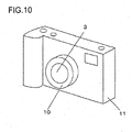
- FIG. 10 is an external view of a camera 11 mounted with a lens barrel 10 achieved in the embodiment.
- the camera 11 may be, for instance, a silver halide film-type camera, a digital camera or a video camera.
- the following explanation is provided by assuming that the lens barrel 10 is mounted at a digital camera.
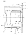
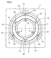
- FIG. 1 is a sectional view of the lens barrel 10 achieved in the embodiment, taken on a plane containing the optical axis and FIG. 2 is a sectional view of the lens barrel taken on a plane perpendicular to the optical axis.
- a holding member 1 is an integrated unit constituted with a fixed tube 1A and a holding unit 1B of an image sensor 6. At the holding member 1, a plurality of projecting tabs 1a are formed and a flange portion 2a of a cam cylinder 2 are rotatably engaged with the tabs 1a.
- the cam cylinder 2 is a small cylinder with three cam grooves 20 formed at the inner circumferential surface thereof.
- the cam cylinder 2 has a diameter of approximately 20 mm or less and is thus too small to allow a plurality of split molds to be used when forming the cam grooves 20.
- FIG. 3 is a development of the cam cylinder 2.
- the cam grooves 20 are each constituted with a recess ranging from one end face of the cam cylinder 2 (the lower end surface in the figure, i.e., the surface coming in contact with the holding unit 1B of the holding member 1) toward the other end, so as to allow a one-piece forming mold used to form the cam grooves 20 to be extracted through rotational extraction. While the cam grooves 20 formed by using the mold assume a shape that allows the mold to be extracted through rotational extraction, the shape of the cam grooves is to be described in detail later.
- a lens holding tube 4, which holds a lens 3, is disposed between the cam cylinder 2 and the fixed tube 1A with three cam followers 4a at the lens holding tube 4 each engaged in one of the three cam grooves 20 at the cam cylinder 2.
- projecting portions 1b formed as an integrated part of the fixed tube 1A engage in linear guide grooves 4b formed at the inner circumferential surface of the lens holding tube 4 so as to allow the lens holding tube 4 to be guided as it moves along the optical axis by disallowing rotation of the lens holding tube 4 relative to the fixed tube 1A.
- cam cylinder 2 As the cam cylinder 2 is caused to rotate by a zoom motor (not shown), displacement of the cam grooves 20 drives the lens holding tube 4 via the cam followers 4a, allowing the lens holding tube 4 and the lens 3 to move forward/backward as one along the optical axis. It is to be noted that the central axis (rotational axis) of the cam cylinder 2 aligns with the optical axis of the lens 3.
- FIG. 1 shows the lens barrel with the lens holding tube 4 and the lens 3 assuming the most driven-in position, i.e. the retracted position
- FIG. 4 shows the lens barrel with the lens holding tube 4 and the lens 3 having been driven out to a first drive position
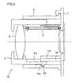
- FIG. 5 shows the lens barrel with the lens holding tube 4 and the lens 3 having been further driven out to a second drive position.
- the zooming operation is executed over the range between the first drive position and the second drive position in response to an operation of a zoom button (not shown), and a photographing operation is allowed if the lens holding tube 4 and the lens 3 assume a position between the first drive position and the second drive position.
- a power off operation the lens 3 is automatically driven in to the retracted position, and then, the power actually goes off.
- the surfaces 21 are hereafter referred to as cam surfaces.
- Pr, Pw and Pt in the figure each indicate the position of the cam follower 4a relative to the corresponding cam surface 21 and respectively correspond to the retracted position, the first drive position and the second drive position.
- the tension springs 5 are pressing members that press the cam followers 4a against the cam surfaces 21.
- the cam surfaces 21 are formed as bent surfaces instead of straight surfaces with the gradient thereof altered within the cam surfaces. Namely, the cam surfaces 21 assume varying gradients.
- the range between the first drive position and the second drive position (between Pw and Pt) is a zoom range over which the lens position affects photographing results. For this reason, the lens position must be controlled with a high level of accuracy. Accordingly, in order to displace the drive target object, i.e., the lens 3, in smaller increments relative to the unit rotational angle by which the cam cylinder 2 rotates, the cam surfaces 21 assume a relatively shallow gradient over the zoom range (first cam surfaces).
- the lens 3 is set /reset over the range between the retracted position and the first drive position (between Pr and Pw).
- this range is not the zoom range, the lens position does not need to be controlled with a very high level of accuracy. Accordingly, the cam surfaces 21 assume a steeper gradient over this range (second cam surfaces) so as to drive the lens further relative to the unit rotational angle of the cam cylinder 2. As a result, the lens 3 can be driven at a higher speed over this range and thus, the lens can be set or reset more quickly as the power is turned on/off to assure improved operability.
- the zoom range (the range between Pw and Pt) defines the range over which the cam followers 4a are allowed to move when a photographing operation is executed in the camera 11 mounted with the lens barrel 10
- the set/reset range (the range between Pr and Pw) defines the range over which the cam followers 4a are allowed to move during the preparatory phase in which the camera 11 is not engaged in photographing operations.
- the word “shallow” as in “shallow gradient” is used to mean that the extent to which the drive target object is made to move per unit rotational angle of the cylinder, i.e., the cam cylinder 2, is small.
- a one-piece mold is used to form the inner circumferential surface of the cam cylinder 2 and then the mold is extracted through rotational extraction.
- the cam surfaces 21 alone are made to include a bend and side surfaces 22 facing opposite the cam surfaces 21, located on the upper side in the figure, are straight.
- the cam grooves 20 are not bent over their entire length, in the embodiment.
- the one-piece mold is designed so that a specific shape is achieved over its cam groove formation areas to form bent cam surfaces 21 and straight side surfaces 22 facing opposite the cam surfaces at the cam grooves 20.
- the gradient of the opposite side surfaces 22 is set equal to the gradient of the cam surfaces 21 over the zoom range, and the distance between the surfaces 21 and 22 over the zoom range, i.e., the width of the cam grooves 20 over the zoom range, is set substantially equal to the diameter of the cam followers 4a.
- the cam followers 4a are guided by both surfaces 21 and 22 over the zoom range, as through standard cam grooves, so as to assure accuracy in the lens drive.
- the cam grooves 20 assume a greater width toward the bottom of the figure and thus, the opposite side surfaces 22 are not used to guide the cam followers 4a.
- the cam followers 4a are pressed against the cam surfaces 21 by the tension springs 5, the lens can still be driven smoothly over this range where the lens position does not need to be controlled with such a high level of accuracy.
- the mold is extracted from the cam cylinder 2 along the axial direction by rotating the mold around the central axis (aligned with the optical axis of the lens 3) of the cam cylinder 2. Since the cam groove formation areas of the mold are eased out along the direction indicated by the arrow A in the figure from the cam grooves 20 along the surfaces 22, the mold can be extracted without difficulty.
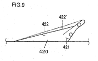
- the gradient of the opposite side surfaces 22 facing opposite the cam surfaces 21 at the cam grooves 20 must be set equal to or shallower than the gradient of the cam surfaces 21 over areas where the cam surfaces assume the shallowest gradient, as shown in FIG. 3 . This requirement is satisfied in each of the other examples of cam grooves 20 presented in FIGS. 6 through 9 .
- FIG. 6 presents an example with the gradient of a cam surface 121 at a cam groove 120 changing in three stages.
- the gradient of an opposite side surface 122 is equal to the gradient at the front end area of the cam surface 121 (over the area where the gradient is at its shallowest) corresponding to an area near the second drive position.
- FIG. 7 shows a cam groove 220 with a cam surface 221 assuming a curved contour.
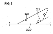
- the gradient of an opposite side surface 222 is equal to the front end area of the cam surface 221 (over the area where the gradient is at its shallowest) corresponding to the second drive position. While the gradient of a cam surface 321 at a cam groove 320 shown in FIG. 8 changes in a reversal from that at the cam surfaces 21 shown in FIG.
- the gradient of the opposite side surface 322 is set equal to the gradient at the base end area (where the gradient is at its shallowest) of the cam surface near the opening end of the cam groove 320.
- FIG. 9 shows a cam groove 420 with its cam surface 421 assuming a shape substantially identical to that shown in FIG. 3
- an opposite side surface 422 is bent so as to assume a shallower gradient on the base end side.
- the cam groove 420 may have a straight opposite side surface 422' with a straight contour, as indicated by the two-point chain line, instead of the bent opposite side surface 422. It is to be noted that the width of the cam groove 420 is greater than the diameter of the cam follower 4a over the zoom range in this case.
- cam drive mechanism according to the present invention may also be adopted in lens drive mechanisms in telescopes and binoculars.
- application of the present invention is not limited to lens drive mechanisms, and the present invention may be adopted in all types of cam drive mechanisms as long as an object needs to be driven linearly through a cam groove formed at the inner circumference of a cylinder.
- the present invention is not limited to this example and it may be adopted in a structure that includes a cam cylinder 2 rotated manually to displace the lens 3 and the lens holding tube 4 along the optical axis.
Landscapes
- Engineering & Computer Science (AREA)
- Physics & Mathematics (AREA)
- Manufacturing & Machinery (AREA)
- Mechanical Engineering (AREA)
- General Engineering & Computer Science (AREA)
- General Physics & Mathematics (AREA)
- Optics & Photonics (AREA)
- Lens Barrels (AREA)
Applications Claiming Priority (2)
| Application Number | Priority Date | Filing Date | Title |
|---|---|---|---|
| JP2005179066A JP4622696B2 (ja) | 2005-06-20 | 2005-06-20 | カム駆動機構 |
| PCT/JP2006/312246 WO2006137362A1 (ja) | 2005-06-20 | 2006-06-19 | カム駆動機構、レンズ鏡筒およびカメラ |
Publications (3)
| Publication Number | Publication Date |
|---|---|
| EP1895342A1 true EP1895342A1 (de) | 2008-03-05 |
| EP1895342A4 EP1895342A4 (de) | 2012-09-26 |
| EP1895342B1 EP1895342B1 (de) | 2013-11-20 |
Family
ID=37570390
Family Applications (1)
| Application Number | Title | Priority Date | Filing Date |
|---|---|---|---|
| EP06766910.1A Ceased EP1895342B1 (de) | 2005-06-20 | 2006-06-19 | Nockenantriebs-mechanismus, linsentubus und kamera |
Country Status (5)
| Country | Link |
|---|---|
| US (1) | US7623302B2 (de) |
| EP (1) | EP1895342B1 (de) |
| JP (1) | JP4622696B2 (de) |
| CN (1) | CN101203788B (de) |
| WO (1) | WO2006137362A1 (de) |
Cited By (1)
| Publication number | Priority date | Publication date | Assignee | Title |
|---|---|---|---|---|
| WO2020128439A1 (en) * | 2018-12-20 | 2020-06-25 | John Guest International Limited | A mold and method for molding a body or cap for a connector |
Families Citing this family (4)
| Publication number | Priority date | Publication date | Assignee | Title |
|---|---|---|---|---|
| JP5807387B2 (ja) * | 2011-05-25 | 2015-11-10 | 株式会社リコー | レンズ鏡筒および撮影装置 |
| JP2017102283A (ja) * | 2015-12-02 | 2017-06-08 | 株式会社ニコン | レンズ鏡筒及び撮像装置 |
| RU2628544C1 (ru) * | 2016-02-25 | 2017-08-18 | Федеральное государственное бюджетное учреждение науки Специальная астрофизическая обсерватория Российской академии наук | Планетарный механизм позиционирования поляриметрической оптики |
| WO2017213266A1 (ja) * | 2016-06-10 | 2017-12-14 | 株式会社ニコン | レンズ鏡筒および撮像装置 |
Family Cites Families (13)
| Publication number | Priority date | Publication date | Assignee | Title |
|---|---|---|---|---|
| DE3903676A1 (de) * | 1988-04-09 | 1989-10-19 | Eti Tec Maschinenbau | Traegerelement fuer die eingriffsglieder eines kurvengetriebes eines antriebes fuer entnahmeelemente in einer etikettierstation sowie mit einem traegerelement ausgeruestete etikettierstation |
| JPH05119248A (ja) * | 1991-10-24 | 1993-05-18 | Ricoh Co Ltd | ズームレンズ駆動装置 |
| GB2311749B (en) * | 1993-12-20 | 1998-04-22 | Asahi Optical Co Ltd | Inner gear formed by injection molding and a mold therefor |
| JP3742444B2 (ja) | 1995-08-09 | 2006-02-01 | ペンタックス株式会社 | レンズ駆動装置 |
| JPH09243897A (ja) * | 1996-03-07 | 1997-09-19 | Canon Inc | レンズ鏡筒および光学機器 |
| JP3253248B2 (ja) | 1996-07-17 | 2002-02-04 | 富士写真光機株式会社 | ヘリコイド構造 |
| JPH1184204A (ja) * | 1997-09-09 | 1999-03-26 | Olympus Optical Co Ltd | 光学機器 |
| JPH11218659A (ja) | 1998-01-30 | 1999-08-10 | Fuji Photo Optical Co Ltd | カメラのレンズ鏡胴 |
| JP4521916B2 (ja) | 2000-02-10 | 2010-08-11 | キヤノン株式会社 | レンズ鏡筒用カム筒、レンズ鏡筒およびこれを備えたカメラ |
| JP3629189B2 (ja) * | 2000-08-09 | 2005-03-16 | ペンタックス株式会社 | 凸カムを有する成形カム環の成形方法、その成形型及び成形カム環 |
| JP2002370268A (ja) | 2001-06-15 | 2002-12-24 | Olympus Optical Co Ltd | 円筒成形品および円筒成形品の形状決定方法 |
| JP4695298B2 (ja) | 2001-06-28 | 2011-06-08 | オリンパス株式会社 | レンズ鏡筒 |
| JP3523249B1 (ja) | 2003-07-31 | 2004-04-26 | 株式会社双信 | カム溝付円筒の製造方法及びこの方法により製造されたカム溝付円筒 |
-
2005
- 2005-06-20 JP JP2005179066A patent/JP4622696B2/ja not_active Expired - Fee Related
-
2006
- 2006-06-19 CN CN2006800223003A patent/CN101203788B/zh not_active Expired - Fee Related
- 2006-06-19 EP EP06766910.1A patent/EP1895342B1/de not_active Ceased
- 2006-06-19 US US11/922,220 patent/US7623302B2/en not_active Expired - Fee Related
- 2006-06-19 WO PCT/JP2006/312246 patent/WO2006137362A1/ja not_active Ceased
Cited By (3)
| Publication number | Priority date | Publication date | Assignee | Title |
|---|---|---|---|---|
| WO2020128439A1 (en) * | 2018-12-20 | 2020-06-25 | John Guest International Limited | A mold and method for molding a body or cap for a connector |
| US11787095B2 (en) | 2018-12-20 | 2023-10-17 | John Guest International Limited | Mold and method for molding a body or cap for a connector |
| AU2019411507B2 (en) * | 2018-12-20 | 2025-09-11 | John Guest International Limited | A mold and method for molding a body or cap for a connector |
Also Published As
| Publication number | Publication date |
|---|---|
| US7623302B2 (en) | 2009-11-24 |
| JP4622696B2 (ja) | 2011-02-02 |
| JP2006350189A (ja) | 2006-12-28 |
| CN101203788B (zh) | 2011-11-09 |
| EP1895342A4 (de) | 2012-09-26 |
| EP1895342B1 (de) | 2013-11-20 |
| WO2006137362A1 (ja) | 2006-12-28 |
| CN101203788A (zh) | 2008-06-18 |
| US20090046377A1 (en) | 2009-02-19 |
Similar Documents
| Publication | Publication Date | Title |
|---|---|---|
| US6490099B2 (en) | Lens device | |
| JPH10293239A (ja) | ズームレンズ鏡筒 | |
| JPH08146278A (ja) | レンズ鏡筒 | |
| JP2002236247A (ja) | バリフォーカルレンズ鏡筒及びレンズ繰出機構 | |
| JP2008249982A (ja) | レンズ鏡筒 | |
| US7623302B2 (en) | Cam drive mechanism, lens barrel and camera | |
| JP4697587B2 (ja) | レンズ鏡胴 | |
| EP1528418A1 (de) | Linsentubus und Bildaufahmevorrichtung | |
| US6639731B1 (en) | Zoom lens barrel assembly of camera | |
| JP2001042189A (ja) | レンズ移動装置 | |
| JPH0534558A (ja) | 焦点可変装置 | |
| US6389231B1 (en) | Lens driving apparatus, lens guiding mechanism, and optical instrument | |
| JP3836232B2 (ja) | レンズ駆動機構 | |
| JPH08211277A (ja) | ズームレンズ鏡筒、及びズームレンズ鏡筒のフランジバックの調整方法 | |
| JP3733048B2 (ja) | 切替群を有するズームレンズ系の切替群用レンズ鏡筒 | |
| JPH0727098B2 (ja) | レンズ移動装置 | |
| JPH10246849A (ja) | レンズ鏡筒 | |
| JP2002236243A (ja) | レンズ鏡筒 | |
| JP2003084177A (ja) | レンズ装置 | |
| JP2010026322A (ja) | レンズ鏡筒 | |
| JP3629230B2 (ja) | 相対回動レンズ保持環の偏心防止装置 | |
| JP4874747B2 (ja) | レンズ駆動装置 | |
| JPH09152542A (ja) | ズームレンズ鏡筒 | |
| JP4434608B2 (ja) | レンズ鏡胴 | |
| JP2002169078A (ja) | レンズ鏡筒 |
Legal Events
| Date | Code | Title | Description |
|---|---|---|---|
| PUAI | Public reference made under article 153(3) epc to a published international application that has entered the european phase |
Free format text: ORIGINAL CODE: 0009012 |
|
| 17P | Request for examination filed |
Effective date: 20080111 |
|
| AK | Designated contracting states |
Kind code of ref document: A1 Designated state(s): DE FR GB |
|
| DAX | Request for extension of the european patent (deleted) | ||
| DAX | Request for extension of the european patent (deleted) | ||
| RBV | Designated contracting states (corrected) |
Designated state(s): DE FR GB |
|
| RAP1 | Party data changed (applicant data changed or rights of an application transferred) |
Owner name: NIKON CORPORATION |
|
| REG | Reference to a national code |
Ref country code: DE Ref legal event code: R079 Ref document number: 602006039333 Country of ref document: DE Free format text: PREVIOUS MAIN CLASS: G02B0007040000 Ipc: G02B0007100000 |
|
| A4 | Supplementary search report drawn up and despatched |
Effective date: 20120824 |
|
| RIC1 | Information provided on ipc code assigned before grant |
Ipc: B29C 45/00 20060101ALI20120820BHEP Ipc: G02B 7/10 20060101AFI20120820BHEP |
|
| GRAP | Despatch of communication of intention to grant a patent |
Free format text: ORIGINAL CODE: EPIDOSNIGR1 |
|
| INTG | Intention to grant announced |
Effective date: 20130619 |
|
| GRAS | Grant fee paid |
Free format text: ORIGINAL CODE: EPIDOSNIGR3 |
|
| GRAA | (expected) grant |
Free format text: ORIGINAL CODE: 0009210 |
|
| AK | Designated contracting states |
Kind code of ref document: B1 Designated state(s): DE FR GB |
|
| REG | Reference to a national code |
Ref country code: GB Ref legal event code: FG4D |
|
| REG | Reference to a national code |
Ref country code: DE Ref legal event code: R096 Ref document number: 602006039333 Country of ref document: DE Effective date: 20140116 |
|
| REG | Reference to a national code |
Ref country code: DE Ref legal event code: R097 Ref document number: 602006039333 Country of ref document: DE |
|
| PLBE | No opposition filed within time limit |
Free format text: ORIGINAL CODE: 0009261 |
|
| STAA | Information on the status of an ep patent application or granted ep patent |
Free format text: STATUS: NO OPPOSITION FILED WITHIN TIME LIMIT |
|
| 26N | No opposition filed |
Effective date: 20140821 |
|
| REG | Reference to a national code |
Ref country code: DE Ref legal event code: R097 Ref document number: 602006039333 Country of ref document: DE Effective date: 20140821 |
|
| REG | Reference to a national code |
Ref country code: FR Ref legal event code: PLFP Year of fee payment: 11 |
|
| REG | Reference to a national code |
Ref country code: FR Ref legal event code: PLFP Year of fee payment: 12 |
|
| REG | Reference to a national code |
Ref country code: FR Ref legal event code: PLFP Year of fee payment: 13 |
|
| PGFP | Annual fee paid to national office [announced via postgrant information from national office to epo] |
Ref country code: FR Payment date: 20200512 Year of fee payment: 15 Ref country code: DE Payment date: 20200609 Year of fee payment: 15 |
|
| PGFP | Annual fee paid to national office [announced via postgrant information from national office to epo] |
Ref country code: GB Payment date: 20200610 Year of fee payment: 15 |
|
| REG | Reference to a national code |
Ref country code: DE Ref legal event code: R082 Ref document number: 602006039333 Country of ref document: DE Representative=s name: VENNER SHIPLEY LLP, DE |
|
| REG | Reference to a national code |
Ref country code: DE Ref legal event code: R119 Ref document number: 602006039333 Country of ref document: DE |
|
| GBPC | Gb: european patent ceased through non-payment of renewal fee |
Effective date: 20210619 |
|
| PG25 | Lapsed in a contracting state [announced via postgrant information from national office to epo] |
Ref country code: GB Free format text: LAPSE BECAUSE OF NON-PAYMENT OF DUE FEES Effective date: 20210619 Ref country code: DE Free format text: LAPSE BECAUSE OF NON-PAYMENT OF DUE FEES Effective date: 20220101 |
|
| PG25 | Lapsed in a contracting state [announced via postgrant information from national office to epo] |
Ref country code: FR Free format text: LAPSE BECAUSE OF NON-PAYMENT OF DUE FEES Effective date: 20210630 |