EP1895561B1 - Elektromagnetische Antriebseinrichtung und elektromechanische Schaltvorrichtung - Google Patents
Elektromagnetische Antriebseinrichtung und elektromechanische Schaltvorrichtung Download PDFInfo
- Publication number
- EP1895561B1 EP1895561B1 EP06018303A EP06018303A EP1895561B1 EP 1895561 B1 EP1895561 B1 EP 1895561B1 EP 06018303 A EP06018303 A EP 06018303A EP 06018303 A EP06018303 A EP 06018303A EP 1895561 B1 EP1895561 B1 EP 1895561B1
- Authority
- EP
- European Patent Office
- Prior art keywords
- drive unit
- electromagnetic drive
- switching device
- electromechanical switching
- current
- Prior art date
- Legal status (The legal status is an assumption and is not a legal conclusion. Google has not performed a legal analysis and makes no representation as to the accuracy of the status listed.)
- Not-in-force
Links
- 238000004804 winding Methods 0.000 claims abstract description 15
- RYGMFSIKBFXOCR-UHFFFAOYSA-N Copper Chemical compound [Cu] RYGMFSIKBFXOCR-UHFFFAOYSA-N 0.000 description 1
- 239000004020 conductor Substances 0.000 description 1
- 230000001419 dependent effect Effects 0.000 description 1
- 230000000694 effects Effects 0.000 description 1
- 230000001939 inductive effect Effects 0.000 description 1
- 239000002184 metal Substances 0.000 description 1
- 229910052751 metal Inorganic materials 0.000 description 1
Images

Classifications
-
- H—ELECTRICITY
- H01—ELECTRIC ELEMENTS
- H01H—ELECTRIC SWITCHES; RELAYS; SELECTORS; EMERGENCY PROTECTIVE DEVICES
- H01H71/00—Details of the protective switches or relays covered by groups H01H73/00 - H01H83/00
- H01H71/10—Operating or release mechanisms
- H01H71/12—Automatic release mechanisms with or without manual release
- H01H71/24—Electromagnetic mechanisms
- H01H71/26—Electromagnetic mechanisms with windings acting in opposition
-
- H—ELECTRICITY
- H01—ELECTRIC ELEMENTS
- H01H—ELECTRIC SWITCHES; RELAYS; SELECTORS; EMERGENCY PROTECTIVE DEVICES
- H01H1/00—Contacts
- H01H1/12—Contacts characterised by the manner in which co-operating contacts engage
- H01H1/14—Contacts characterised by the manner in which co-operating contacts engage by abutting
- H01H1/20—Bridging contacts
-
- H—ELECTRICITY
- H01—ELECTRIC ELEMENTS
- H01H—ELECTRIC SWITCHES; RELAYS; SELECTORS; EMERGENCY PROTECTIVE DEVICES
- H01H1/00—Contacts
- H01H1/12—Contacts characterised by the manner in which co-operating contacts engage
- H01H1/14—Contacts characterised by the manner in which co-operating contacts engage by abutting
- H01H1/24—Contacts characterised by the manner in which co-operating contacts engage by abutting with resilient mounting
-
- H—ELECTRICITY
- H01—ELECTRIC ELEMENTS
- H01H—ELECTRIC SWITCHES; RELAYS; SELECTORS; EMERGENCY PROTECTIVE DEVICES
- H01H71/00—Details of the protective switches or relays covered by groups H01H73/00 - H01H83/00
- H01H71/10—Operating or release mechanisms
- H01H71/12—Automatic release mechanisms with or without manual release
- H01H71/24—Electromagnetic mechanisms
- H01H2071/249—Electromagnetic mechanisms with part of the magnetic circuit being in the normal current path in the circuit breaker, e.g. yoke, fixed contact and arc-runner are made out of one single conductive element
Definitions
- the invention relates to the art of designing electromagnetic drive units and to electromechanical switching devices.
- electromagnetic trigger units In the field of low-voltage switching devices that are adapted to switch electric currents over voltages from 100 V up to 1000 V, electromagnetic trigger units, sometimes referred to as n-triggers, are implemented with an electromagnetic drive unit comprising a coil, a yoke and an armature.
- An electromagnetic trigger unit is an unit that limits or breaks the current passing through an electromechanical switching device in the event of short-circuit.
- the trigger unit uses the force generated by the coil and yoke to push or pull the armature so that the current path is broken or limited.
- Electromagnetic trigger units are commonly used in circuit breakers and current limiters.
- An electromagnetic trigger unit is usually adapted to break or limit the current if the rated current is exceeded.
- the coil in the electromagnetic drive unit must be able to generate a strong enough magnet field to pull or push the armature with enough force. For electromechanical switching devices that have small rated currents this may be a problem, since the magnet field is proportional to the current flowing through the coil.
- a winding having a small cross section is not very stable if large currents are carried through it, and so the copper wire of which the winding has been made tends to get permanently damaged in the case of short circuit.
- Document EP 0 626 713 discloses a device according to the preamble of claim 1.
- a second object of the invention is to improve the stability of an electromechanical switching device against short circuit. This object can be achieved as set out in claim 3.
- the winding of the coil of an electromagnetic drive unit comprising a coil, a yoke and an armature is partly wound in one direction and partly in the other direction, one part of the winding will carry current in the other direction than the other part of the winding. Because of the compensating effect of the other part, a part of the winding may not become magnetically effective under normal conditions. But in the event of short circuit, the inductive resistance of the part of the winding that has been wound in the other direction becomes significant and thus tends to limit the short circuit current.
- an electromechanical switching device comprising at least one input terminal, a respective output terminal, and an electromagnetic drive unit according to the first aspect of the invention, if the electromagnetic drive unit is adapted to limit or to break the electrical current between said at least one input terminal.
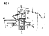
- Figure 1 shows a current limiter 10 comprising a first current input terminal A1 and a responsive current output terminal T1.
- the limiter 10 is a limiter for a three-phase current, but for simplicity the components for the two other phases have been omitted from Figure 1 .
- Each input terminal A1 of the current limiter 10 receives a phase of a three-phase electric circuit, and passes the electric current via a current rail 11 to a stationary contact piece 12. If the contact bridge 14 is in its normal position, the stationary contact piece 12 is in electrical contact with the movable contact piece 13.
- the movable contact piece 13 is in electrical contact with the second movable contact piece 15 via the contact bridge 14. If the contact bridge 14 is still in its normal position, the second movable contact piece 15 is in electrical contact with the second stationary contact piece 16, from which the current may flow via a second current rail 17 to the responsive output terminal T1.
- the electric current passing through the contact bridge 14 passed, advantageously after the second stationary contact 16, through an metal conductor 18 to a coil 21 of an electromagnetic drive unit 20.
- the electromagnetic drive unit 20 monitors the electric current flowing through the limiter 10, and if it detects an excessive electric current, it limits it by displacing the movable contacts 13, 15 from the stationary contacts 12, 16 by exerting a force to the armature 23A that moves the plunger 23 connected to the contact bridge 14.
- a biasing spring 24 ensures that the movable contacts 13, 15 cannot be displaced from the stationary contacts 12, 16 until an excessive current is reached, i.e. that the electromagnetic drive unit 20 generates a force F to the armature 23A that is large enough to exceed the balancing force of the biasing spring 24.
- the electromagnetic drive unit 20 comprises a coil 21, a yoke 22 and an armature 23A.
- the winding 41 of the coil 21, illustrated in Figure 2 is partly wound in one direction and partly in the other direction.
- the winding 41 may change its direction layerwise, i.e. having one or more layers 51 in one direction and then one or more layers 52 in the other direction.
Landscapes
- Physics & Mathematics (AREA)
- Electromagnetism (AREA)
- Driving Mechanisms And Operating Circuits Of Arc-Extinguishing High-Tension Switches (AREA)
- Emergency Protection Circuit Devices (AREA)
- Vehicle Body Suspensions (AREA)
- Portable Nailing Machines And Staplers (AREA)
- Brushes (AREA)
- Electromagnets (AREA)
- Reciprocating, Oscillating Or Vibrating Motors (AREA)
Claims (5)
- Elektromagnetische Antriebseinheit (20), die eine Spule (21), ein Joch (22) und einen Anker (23A) umfasst, dadurch gekennzeichnet, dass die Wicklung (41) der Spule (21) zum Teil in eine Richtung und zum Teil in die andere Richtung gewickelt ist.
- Elektromagnetische Antriebseinheit (20) nach Anspruch 1, bei der die Wicklung (41) schichtweise (51, 52) ihre Richtung ändert.
- Elektromechanische Schaltvorrichtung (10), die Folgendes umfasst:i) mindestens einen Eingangsanschluss (A1) und einen entsprechenden Ausgangsanschluss (T1),ii) eine elektromagnetische Antriebseinheit (20) nach Anspruch 1 oder 2, die so ausgelegt ist, dass sie den elektrischen Strom zwischen dem mindestens einen Eingangsanschluss (A1) und dem entsprechenden Ausgangsanschluss (T1) begrenzt oder unterbricht.
- Elektromechanische Schaltvorrichtung (10) nach Anspruch 3, wobei es sich bei der elektromechanischen Schaltvorrichtung (10) um einen Leistungsschalter handelt.
- Elektromechanische Schaltvorrichtung (10) nach Anspruch 4, wobei es sich bei der elektromechanischen Schaltvorrichtung (10) um einen Strombegrenzer handelt.
Priority Applications (7)
| Application Number | Priority Date | Filing Date | Title |
|---|---|---|---|
| EP06018303A EP1895561B1 (de) | 2006-09-01 | 2006-09-01 | Elektromagnetische Antriebseinrichtung und elektromechanische Schaltvorrichtung |
| AT06018303T ATE431962T1 (de) | 2006-09-01 | 2006-09-01 | Elektromagnetische antriebseinrichtung und elektromechanische schaltvorrichtung |
| DE602006006911T DE602006006911D1 (de) | 2006-09-01 | 2006-09-01 | Elektromagnetische Antriebseinrichtung und elektromechanische Schaltvorrichtung |
| CN2007800317096A CN101506925B (zh) | 2006-09-01 | 2007-08-16 | 电磁驱动单元和机电切换装置 |
| KR1020097006613A KR101457363B1 (ko) | 2006-09-01 | 2007-08-16 | 전자기 구동 유니트 및 전기기계적 스위칭 장치 |
| US12/310,311 US8143977B2 (en) | 2006-09-01 | 2007-08-16 | Electromagnetic drive and an electromechanical switching device |
| PCT/EP2007/058536 WO2008025685A1 (en) | 2006-09-01 | 2007-08-16 | An electromagnetic drive unit and an electromechanical switching device |
Applications Claiming Priority (1)
| Application Number | Priority Date | Filing Date | Title |
|---|---|---|---|
| EP06018303A EP1895561B1 (de) | 2006-09-01 | 2006-09-01 | Elektromagnetische Antriebseinrichtung und elektromechanische Schaltvorrichtung |
Publications (2)
| Publication Number | Publication Date |
|---|---|
| EP1895561A1 EP1895561A1 (de) | 2008-03-05 |
| EP1895561B1 true EP1895561B1 (de) | 2009-05-20 |
Family
ID=37668316
Family Applications (1)
| Application Number | Title | Priority Date | Filing Date |
|---|---|---|---|
| EP06018303A Not-in-force EP1895561B1 (de) | 2006-09-01 | 2006-09-01 | Elektromagnetische Antriebseinrichtung und elektromechanische Schaltvorrichtung |
Country Status (7)
| Country | Link |
|---|---|
| US (1) | US8143977B2 (de) |
| EP (1) | EP1895561B1 (de) |
| KR (1) | KR101457363B1 (de) |
| CN (1) | CN101506925B (de) |
| AT (1) | ATE431962T1 (de) |
| DE (1) | DE602006006911D1 (de) |
| WO (1) | WO2008025685A1 (de) |
Family Cites Families (7)
| Publication number | Priority date | Publication date | Assignee | Title |
|---|---|---|---|---|
| US3706916A (en) * | 1972-01-19 | 1972-12-19 | Cutler Hammer Inc | Remote control circuit breaker system |
| US4876521A (en) | 1987-08-25 | 1989-10-24 | Siemens Energy & Automation, Inc. | Tripping coil with flux shifting coil and booster coil |
| DE3908350A1 (de) * | 1989-03-15 | 1990-09-20 | Asea Brown Boveri | Elektrische spule |
| US5565833A (en) * | 1993-05-28 | 1996-10-15 | Circuit Breaker Industries Limited | Method of fitting a coil onto a bobbin |
| US5684443A (en) * | 1995-12-21 | 1997-11-04 | Philips Electronics North America Corporation | False-trip-resistant circuit breaker |
| TR200000748T2 (tr) * | 1997-09-18 | 2000-06-21 | Holec Holland N.V. | Elektromanyetik aktüatör |
| CN2344849Y (zh) * | 1998-08-20 | 1999-10-20 | 北京开关厂 | 操动机构分闸电磁铁 |
-
2006
- 2006-09-01 EP EP06018303A patent/EP1895561B1/de not_active Not-in-force
- 2006-09-01 AT AT06018303T patent/ATE431962T1/de not_active IP Right Cessation
- 2006-09-01 DE DE602006006911T patent/DE602006006911D1/de active Active
-
2007
- 2007-08-16 WO PCT/EP2007/058536 patent/WO2008025685A1/en not_active Ceased
- 2007-08-16 US US12/310,311 patent/US8143977B2/en not_active Expired - Fee Related
- 2007-08-16 KR KR1020097006613A patent/KR101457363B1/ko not_active Expired - Fee Related
- 2007-08-16 CN CN2007800317096A patent/CN101506925B/zh not_active Expired - Fee Related
Also Published As
| Publication number | Publication date |
|---|---|
| CN101506925B (zh) | 2013-01-02 |
| DE602006006911D1 (de) | 2009-07-02 |
| EP1895561A1 (de) | 2008-03-05 |
| US20090243770A1 (en) | 2009-10-01 |
| ATE431962T1 (de) | 2009-06-15 |
| KR20090066279A (ko) | 2009-06-23 |
| WO2008025685A1 (en) | 2008-03-06 |
| US8143977B2 (en) | 2012-03-27 |
| KR101457363B1 (ko) | 2014-11-03 |
| CN101506925A (zh) | 2009-08-12 |
Similar Documents
| Publication | Publication Date | Title |
|---|---|---|
| CN101252055B (zh) | 断路器及其开闭方法 | |
| EP2251887A1 (de) | Elektromagnetische Schnellauslösevorrichtung | |
| EP2777058B1 (de) | Elektrisches schaltgerät mit magnetanordnung und einer ersten und zweiten löschkammer | |
| US8159807B2 (en) | Method and device for operating a switching device | |
| KR101050354B1 (ko) | 회로 차단기 | |
| CN101944442B (zh) | 由磁性补偿装置的伺服控制和包括该装置的接触器 | |
| EP2509092B1 (de) | Elektrische Schaltvorrichtung | |
| KR101472555B1 (ko) | 순간정전 방지 및 저전압 방지 기능이 내장된 전자 접촉기를 구비한 분전반 및 전동기 제어반 | |
| US5684443A (en) | False-trip-resistant circuit breaker | |
| EP1895561A1 (de) | Elektromagnetische Antriebseinrichtung und elektromechanische Schaltvorrichtung | |
| RU2262768C1 (ru) | Выключатель автоматический быстродействующий постоянного тока | |
| KR20150010958A (ko) | 회로 차단기 제어를 위한 액추에이터 회로 | |
| CN102568960B (zh) | 限流电路断路器 | |
| KR101607071B1 (ko) | 순간 정전 방지 기능이 내장된 전자 접촉기 | |
| KR101640144B1 (ko) | 저전압 방지 기능이 내장된 전자 접촉기 | |
| US10043627B2 (en) | Device for monitoring a current of a primary conductor with respect to a predetermined current threshold, and related trip assembly and switching device | |
| KR100516223B1 (ko) | 차단기의 원추 형상 코아를 가진 코일 장치 | |
| RU2795269C1 (ru) | Поляризованный быстродействующий электромагнит | |
| EP1895562A1 (de) | Ein Strombegrenzer | |
| US20250079101A1 (en) | Magnetic switch for hybrid circuit breaker applications | |
| RU2321095C1 (ru) | Электромагнитный привод выключателя автоматического быстродействующего | |
| KR101640145B1 (ko) | 순간정전 방지 및 저전압 방지 기능이 내장된 전자 접촉기 | |
| EP1906427A1 (de) | Elektromagnetische Antriebseinheit und elektromagnetische Schaltvorrichtung | |
| WO2022238014A1 (en) | Device and method for inducing a voltage into an electric circuit and zero-voltage switch with means to generate a counter voltage counteracting a grid voltage | |
| KR20110035544A (ko) | 변압기 보호 장치 |
Legal Events
| Date | Code | Title | Description |
|---|---|---|---|
| PUAI | Public reference made under article 153(3) epc to a published international application that has entered the european phase |
Free format text: ORIGINAL CODE: 0009012 |
|
| AK | Designated contracting states |
Kind code of ref document: A1 Designated state(s): AT BE BG CH CY CZ DE DK EE ES FI FR GB GR HU IE IS IT LI LT LU LV MC NL PL PT RO SE SI SK TR |
|
| AX | Request for extension of the european patent |
Extension state: AL BA HR MK YU |
|
| 17P | Request for examination filed |
Effective date: 20080320 |
|
| GRAP | Despatch of communication of intention to grant a patent |
Free format text: ORIGINAL CODE: EPIDOSNIGR1 |
|
| AKX | Designation fees paid |
Designated state(s): AT BE BG CH CY CZ DE DK EE ES FI FR GB GR HU IE IS IT LI LT LU LV MC NL PL PT RO SE SI SK TR |
|
| GRAS | Grant fee paid |
Free format text: ORIGINAL CODE: EPIDOSNIGR3 |
|
| GRAA | (expected) grant |
Free format text: ORIGINAL CODE: 0009210 |
|
| AK | Designated contracting states |
Kind code of ref document: B1 Designated state(s): AT BE BG CH CY CZ DE DK EE ES FI FR GB GR HU IE IS IT LI LT LU LV MC NL PL PT RO SE SI SK TR |
|
| REG | Reference to a national code |
Ref country code: GB Ref legal event code: FG4D |
|
| REG | Reference to a national code |
Ref country code: CH Ref legal event code: EP |
|
| REG | Reference to a national code |
Ref country code: IE Ref legal event code: FG4D |
|
| REF | Corresponds to: |
Ref document number: 602006006911 Country of ref document: DE Date of ref document: 20090702 Kind code of ref document: P |
|
| PG25 | Lapsed in a contracting state [announced via postgrant information from national office to epo] |
Ref country code: AT Free format text: LAPSE BECAUSE OF FAILURE TO SUBMIT A TRANSLATION OF THE DESCRIPTION OR TO PAY THE FEE WITHIN THE PRESCRIBED TIME-LIMIT Effective date: 20090520 Ref country code: FI Free format text: LAPSE BECAUSE OF FAILURE TO SUBMIT A TRANSLATION OF THE DESCRIPTION OR TO PAY THE FEE WITHIN THE PRESCRIBED TIME-LIMIT Effective date: 20090520 Ref country code: PT Free format text: LAPSE BECAUSE OF FAILURE TO SUBMIT A TRANSLATION OF THE DESCRIPTION OR TO PAY THE FEE WITHIN THE PRESCRIBED TIME-LIMIT Effective date: 20090920 Ref country code: LT Free format text: LAPSE BECAUSE OF FAILURE TO SUBMIT A TRANSLATION OF THE DESCRIPTION OR TO PAY THE FEE WITHIN THE PRESCRIBED TIME-LIMIT Effective date: 20090520 Ref country code: ES Free format text: LAPSE BECAUSE OF FAILURE TO SUBMIT A TRANSLATION OF THE DESCRIPTION OR TO PAY THE FEE WITHIN THE PRESCRIBED TIME-LIMIT Effective date: 20090831 |
|
| NLV1 | Nl: lapsed or annulled due to failure to fulfill the requirements of art. 29p and 29m of the patents act | ||
| PG25 | Lapsed in a contracting state [announced via postgrant information from national office to epo] |
Ref country code: SE Free format text: LAPSE BECAUSE OF FAILURE TO SUBMIT A TRANSLATION OF THE DESCRIPTION OR TO PAY THE FEE WITHIN THE PRESCRIBED TIME-LIMIT Effective date: 20090820 Ref country code: NL Free format text: LAPSE BECAUSE OF FAILURE TO SUBMIT A TRANSLATION OF THE DESCRIPTION OR TO PAY THE FEE WITHIN THE PRESCRIBED TIME-LIMIT Effective date: 20090520 Ref country code: PL Free format text: LAPSE BECAUSE OF FAILURE TO SUBMIT A TRANSLATION OF THE DESCRIPTION OR TO PAY THE FEE WITHIN THE PRESCRIBED TIME-LIMIT Effective date: 20090520 Ref country code: LV Free format text: LAPSE BECAUSE OF FAILURE TO SUBMIT A TRANSLATION OF THE DESCRIPTION OR TO PAY THE FEE WITHIN THE PRESCRIBED TIME-LIMIT Effective date: 20090520 Ref country code: IS Free format text: LAPSE BECAUSE OF FAILURE TO SUBMIT A TRANSLATION OF THE DESCRIPTION OR TO PAY THE FEE WITHIN THE PRESCRIBED TIME-LIMIT Effective date: 20090920 Ref country code: SI Free format text: LAPSE BECAUSE OF FAILURE TO SUBMIT A TRANSLATION OF THE DESCRIPTION OR TO PAY THE FEE WITHIN THE PRESCRIBED TIME-LIMIT Effective date: 20090520 |
|
| PG25 | Lapsed in a contracting state [announced via postgrant information from national office to epo] |
Ref country code: CZ Free format text: LAPSE BECAUSE OF FAILURE TO SUBMIT A TRANSLATION OF THE DESCRIPTION OR TO PAY THE FEE WITHIN THE PRESCRIBED TIME-LIMIT Effective date: 20090520 Ref country code: DK Free format text: LAPSE BECAUSE OF FAILURE TO SUBMIT A TRANSLATION OF THE DESCRIPTION OR TO PAY THE FEE WITHIN THE PRESCRIBED TIME-LIMIT Effective date: 20090520 Ref country code: RO Free format text: LAPSE BECAUSE OF FAILURE TO SUBMIT A TRANSLATION OF THE DESCRIPTION OR TO PAY THE FEE WITHIN THE PRESCRIBED TIME-LIMIT Effective date: 20090520 Ref country code: EE Free format text: LAPSE BECAUSE OF FAILURE TO SUBMIT A TRANSLATION OF THE DESCRIPTION OR TO PAY THE FEE WITHIN THE PRESCRIBED TIME-LIMIT Effective date: 20090520 |
|
| PG25 | Lapsed in a contracting state [announced via postgrant information from national office to epo] |
Ref country code: SK Free format text: LAPSE BECAUSE OF FAILURE TO SUBMIT A TRANSLATION OF THE DESCRIPTION OR TO PAY THE FEE WITHIN THE PRESCRIBED TIME-LIMIT Effective date: 20090520 Ref country code: BE Free format text: LAPSE BECAUSE OF FAILURE TO SUBMIT A TRANSLATION OF THE DESCRIPTION OR TO PAY THE FEE WITHIN THE PRESCRIBED TIME-LIMIT Effective date: 20090520 |
|
| PLBE | No opposition filed within time limit |
Free format text: ORIGINAL CODE: 0009261 |
|
| STAA | Information on the status of an ep patent application or granted ep patent |
Free format text: STATUS: NO OPPOSITION FILED WITHIN TIME LIMIT |
|
| PG25 | Lapsed in a contracting state [announced via postgrant information from national office to epo] |
Ref country code: BG Free format text: LAPSE BECAUSE OF FAILURE TO SUBMIT A TRANSLATION OF THE DESCRIPTION OR TO PAY THE FEE WITHIN THE PRESCRIBED TIME-LIMIT Effective date: 20090820 |
|
| 26N | No opposition filed |
Effective date: 20100223 |
|
| PG25 | Lapsed in a contracting state [announced via postgrant information from national office to epo] |
Ref country code: MC Free format text: LAPSE BECAUSE OF NON-PAYMENT OF DUE FEES Effective date: 20090930 |
|
| REG | Reference to a national code |
Ref country code: IE Ref legal event code: MM4A |
|
| PG25 | Lapsed in a contracting state [announced via postgrant information from national office to epo] |
Ref country code: IE Free format text: LAPSE BECAUSE OF NON-PAYMENT OF DUE FEES Effective date: 20090901 |
|
| PG25 | Lapsed in a contracting state [announced via postgrant information from national office to epo] |
Ref country code: GR Free format text: LAPSE BECAUSE OF FAILURE TO SUBMIT A TRANSLATION OF THE DESCRIPTION OR TO PAY THE FEE WITHIN THE PRESCRIBED TIME-LIMIT Effective date: 20090821 |
|
| PG25 | Lapsed in a contracting state [announced via postgrant information from national office to epo] |
Ref country code: LU Free format text: LAPSE BECAUSE OF NON-PAYMENT OF DUE FEES Effective date: 20090901 |
|
| REG | Reference to a national code |
Ref country code: CH Ref legal event code: PL |
|
| GBPC | Gb: european patent ceased through non-payment of renewal fee |
Effective date: 20100901 |
|
| PG25 | Lapsed in a contracting state [announced via postgrant information from national office to epo] |
Ref country code: HU Free format text: LAPSE BECAUSE OF FAILURE TO SUBMIT A TRANSLATION OF THE DESCRIPTION OR TO PAY THE FEE WITHIN THE PRESCRIBED TIME-LIMIT Effective date: 20091121 |
|
| PG25 | Lapsed in a contracting state [announced via postgrant information from national office to epo] |
Ref country code: LI Free format text: LAPSE BECAUSE OF NON-PAYMENT OF DUE FEES Effective date: 20100930 Ref country code: CH Free format text: LAPSE BECAUSE OF NON-PAYMENT OF DUE FEES Effective date: 20100930 |
|
| PG25 | Lapsed in a contracting state [announced via postgrant information from national office to epo] |
Ref country code: GB Free format text: LAPSE BECAUSE OF NON-PAYMENT OF DUE FEES Effective date: 20100901 Ref country code: TR Free format text: LAPSE BECAUSE OF FAILURE TO SUBMIT A TRANSLATION OF THE DESCRIPTION OR TO PAY THE FEE WITHIN THE PRESCRIBED TIME-LIMIT Effective date: 20090520 |
|
| PG25 | Lapsed in a contracting state [announced via postgrant information from national office to epo] |
Ref country code: CY Free format text: LAPSE BECAUSE OF FAILURE TO SUBMIT A TRANSLATION OF THE DESCRIPTION OR TO PAY THE FEE WITHIN THE PRESCRIBED TIME-LIMIT Effective date: 20090520 |
|
| REG | Reference to a national code |
Ref country code: FR Ref legal event code: PLFP Year of fee payment: 11 |
|
| PGFP | Annual fee paid to national office [announced via postgrant information from national office to epo] |
Ref country code: FR Payment date: 20160914 Year of fee payment: 11 |
|
| PGFP | Annual fee paid to national office [announced via postgrant information from national office to epo] |
Ref country code: DE Payment date: 20161121 Year of fee payment: 11 |
|
| PGFP | Annual fee paid to national office [announced via postgrant information from national office to epo] |
Ref country code: IT Payment date: 20160928 Year of fee payment: 11 |
|
| REG | Reference to a national code |
Ref country code: DE Ref legal event code: R119 Ref document number: 602006006911 Country of ref document: DE |
|
| REG | Reference to a national code |
Ref country code: FR Ref legal event code: ST Effective date: 20180531 |
|
| PG25 | Lapsed in a contracting state [announced via postgrant information from national office to epo] |
Ref country code: DE Free format text: LAPSE BECAUSE OF NON-PAYMENT OF DUE FEES Effective date: 20180404 |
|
| PG25 | Lapsed in a contracting state [announced via postgrant information from national office to epo] |
Ref country code: FR Free format text: LAPSE BECAUSE OF NON-PAYMENT OF DUE FEES Effective date: 20171002 Ref country code: IT Free format text: LAPSE BECAUSE OF NON-PAYMENT OF DUE FEES Effective date: 20170901 |