EP1895678A2 - Procédé pour réduction de l'interférence intercellulaire dans un système de communication mobile - Google Patents
Procédé pour réduction de l'interférence intercellulaire dans un système de communication mobile Download PDFInfo
- Publication number
- EP1895678A2 EP1895678A2 EP20070253403 EP07253403A EP1895678A2 EP 1895678 A2 EP1895678 A2 EP 1895678A2 EP 20070253403 EP20070253403 EP 20070253403 EP 07253403 A EP07253403 A EP 07253403A EP 1895678 A2 EP1895678 A2 EP 1895678A2
- Authority
- EP
- European Patent Office
- Prior art keywords
- frequency band
- signal
- signal power
- channel
- mobile communication
- Prior art date
- Legal status (The legal status is an assumption and is not a legal conclusion. Google has not performed a legal analysis and makes no representation as to the accuracy of the status listed.)
- Granted
Links
Images




Classifications
-
- H—ELECTRICITY
- H04—ELECTRIC COMMUNICATION TECHNIQUE
- H04W—WIRELESS COMMUNICATION NETWORKS
- H04W52/00—Power management, e.g. Transmission Power Control [TPC] or power classes
- H04W52/04—Transmission power control [TPC]
- H04W52/06—TPC algorithms
- H04W52/14—Separate analysis of uplink or downlink
- H04W52/146—Uplink power control
-
- H—ELECTRICITY
- H04—ELECTRIC COMMUNICATION TECHNIQUE
- H04L—TRANSMISSION OF DIGITAL INFORMATION, e.g. TELEGRAPHIC COMMUNICATION
- H04L25/00—Baseband systems
- H04L25/02—Details ; arrangements for supplying electrical power along data transmission lines
- H04L25/03—Shaping networks in transmitter or receiver, e.g. adaptive shaping networks
- H04L25/03006—Arrangements for removing intersymbol interference
- H04L25/03178—Arrangements involving sequence estimation techniques
- H04L25/03248—Arrangements for operating in conjunction with other apparatus
- H04L25/0328—Arrangements for operating in conjunction with other apparatus with interference cancellation circuitry
-
- H—ELECTRICITY
- H04—ELECTRIC COMMUNICATION TECHNIQUE
- H04L—TRANSMISSION OF DIGITAL INFORMATION, e.g. TELEGRAPHIC COMMUNICATION
- H04L5/00—Arrangements affording multiple use of the transmission path
- H04L5/14—Two-way operation using the same type of signal, i.e. duplex
-
- H—ELECTRICITY
- H04—ELECTRIC COMMUNICATION TECHNIQUE
- H04W—WIRELESS COMMUNICATION NETWORKS
- H04W52/00—Power management, e.g. Transmission Power Control [TPC] or power classes
- H04W52/04—Transmission power control [TPC]
- H04W52/18—TPC being performed according to specific parameters
- H04W52/24—TPC being performed according to specific parameters using SIR [Signal to Interference Ratio] or other wireless path parameters
- H04W52/243—TPC being performed according to specific parameters using SIR [Signal to Interference Ratio] or other wireless path parameters taking into account interferences
- H04W52/244—Interferences in heterogeneous networks, e.g. among macro and femto or pico cells or other sector / system interference [OSI]
-
- H—ELECTRICITY
- H04—ELECTRIC COMMUNICATION TECHNIQUE
- H04W—WIRELESS COMMUNICATION NETWORKS
- H04W52/00—Power management, e.g. Transmission Power Control [TPC] or power classes
- H04W52/04—Transmission power control [TPC]
- H04W52/18—TPC being performed according to specific parameters
- H04W52/24—TPC being performed according to specific parameters using SIR [Signal to Interference Ratio] or other wireless path parameters
- H04W52/245—TPC being performed according to specific parameters using SIR [Signal to Interference Ratio] or other wireless path parameters taking into account received signal strength
-
- H—ELECTRICITY
- H04—ELECTRIC COMMUNICATION TECHNIQUE
- H04W—WIRELESS COMMUNICATION NETWORKS
- H04W52/00—Power management, e.g. Transmission Power Control [TPC] or power classes
- H04W52/04—Transmission power control [TPC]
- H04W52/18—TPC being performed according to specific parameters
- H04W52/24—TPC being performed according to specific parameters using SIR [Signal to Interference Ratio] or other wireless path parameters
- H04W52/246—TPC being performed according to specific parameters using SIR [Signal to Interference Ratio] or other wireless path parameters where the output power of a terminal is based on a path parameter calculated in said terminal
Definitions
- the present invention relates to a mobile communication system with reduced inter-cell interference (ICI) and a method thereof, and more particularly, to a mobile communication system with reduced ICI by controlling an uplink signal's transmission signal power based on power measurement of a signal received from a base station, and a method thereof.
- ICI inter-cell interference
- Mobile communication technology includes a mobile communication device usable by a user in a moving object, such as a train, a ship, or an airplane, or while the user is walking.
- FIG. 1 illustrates a cell structure of a mobile communication system in which a mobile communication device may be used according to the conventional art.
- a mobile communication system includes base stations 111, 112, and 113, and mobile communication devices, which may be referred to as mobile stations or a mobile communication terminals (hereinafter, referred to individually as a "terminal") 121, 122, and 123.
- Each base station 111, 112, and 113 provides mobile communication services to a respective wireless communication area called a "cell.”
- Each terminal 121, 122, and 123 may be located in a cell corresponding to one of the base stations 111, 112, and 113, and respectively receives mobile communication service via the base stations 111, 112, and 113.
- a base station 111, 112, or 113 in a cell may be affected by multiple access interference corresponding to signal interference from a terminal located within the cell, and inter-cell interference (ICI) corresponding to signal interference from a terminal located in a neighboring cell.
- ICI inter-cell interference
- Orthogonal frequency division multiplexing (OFDM) technology has been developed, and may be able to reduce multiple access interference.
- OFDM Orthogonal frequency division multiplexing
- ICI and in particular, ICI of an uplink channel has not been solved through the use of OFDM.
- a terminal near a cell boundary may have signal distortion due to the ICI. Accordingly, for reliable data transmission, channel coding is performed with an extremely low channel coding rate and then data is transmitted.
- WiBro Wireless Broadband
- a portable internet Wireless Broadband (WiBro) standard uses a coding rate of 1/12.
- FIG. 2 illustrates an example of a frequency band allocation method based on fractional frequency reuse (FFR) according to the conventional art.
- terminals located in the centers of cell (1) 221 (cell 221), cell (2) 222 (cell 222), and cell (3) 223 (cell 223) use the same frequency band 210.
- a terminal near a cell boundary may not use one predetermined frequency band from among three frequency bands 211, 212, and 213 or may use the predetermined frequency band at a lower power to avoid frequency duplication with a neighboring cell.
- a terminal near a boundary of the cell 221 may not use a first fractional frequency band 211 or may use the first fractional frequency band 211 with a low power.
- another terminal near to a boundary of the cell 222 may not use a second fractional frequency band 212 or may use the second fractional frequency band 212 with a low power.
- still another terminal near to a boundary of the cell 223 may not use a third fractional frequency band 213 or may use the third fractional frequency band 213 with a low power.
- the terminal may reduce ICI, but a frequency reuse factor of a terminal located in an outer boundary of a cell is reduced to 2/3 without regard for the actual use of the three frequency bands prior to avoiding frequency duplication with a neighboring cell.
- FIG. 3 illustrates another frequency band allocation method for ICI reduction according to the conventional art.
- a cell is divided into a central area (a white area) and an outer boundary (a shaded area).
- frequency bands are allocated so that a mobile terminal in the central area may use a common frequency band with neighboring cells, and a terminal of the outer boundary may use a frequency band that is not used in neighboring cells.
- a cell (2) 302 (cell 302), a cell (3) 303 (cell 303), a cell (4) 304 (cell 304), a cell (5) 305 (cell 305), a cell (6) 306 (cell 306), and a cell (7) 307 (cell 307) neighbor a cell (1) 301 (cell 301).
- a first frequency band is allocated to an outer boundary of the cell 301, but is not duplicated with a second frequency band or a third frequency band allocated to outer boundaries of the cells 302 through 307.
- An outer boundary area of the first frequency band is allocated is marked in black.
- the cells 302, 304, and 306, which are allocated with the second frequency band and for which the outer boundaries are hatched with dots, are spaced apart from each other.
- the cells 303, 305, and 307 which are allocated with the third frequency band and for which the outer boundaries are hatched with diagonal lines, are spaced apart from each other.
- the ICI reduction scheme shown in FIG. 3 may allocate a frequency band not to be used between neighboring cells in an outer boundary with the most severe ICI, and thereby reducing the ICI.
- ICI reduction schemes are commonly based on an idea of ICI coordination/avoidance that limits frequency use time or frequency resource for a terminal located in an outer boundary of a cell.
- a cell area has a distorted shape that is different than a theoretical hexagonal cell arrangement. Accordingly, it is more difficult to separately manage frequency bands for the central area and the outer boundary.
- trunking efficiency may be reduced. Specifically, wireless resources may be exhausted when more terminals are located in the outer boundary of the cell.
- frequency hopping may be reduced. Accordingly, frequency diversity effect may be reduced, and thus a multi-path signal may not be effectively processed.
- a frequency band is allocated to a terminal located in an outer boundary of a cell based on a relation with a neighboring cell, flexible cell planning is difficult. For example, adding an additional base station and an additional cell between existing cells, a new frequency band should be allocated to cells adjacent to the additional cell, and this may require the modification of the cell planning.
- a portion of the frequency band may be unused even when there is no ICI. Accordingly, wireless resources may not be effectively managed.
- an upper layer service control point (SCP) or a mobile switching center (MSC) should be in charge of cell planning and coordination for a plurality of base stations.
- SCP upper layer service control point
- MSC mobile switching center
- IP ALL-Internet Protocol
- This invention provides an ICI reduction method and an uplink channel resources management method for a mobile communication system.
- This invention also provides a mobile communication system and mobile communication terminal able to reduce ICI and manage uplink channel resources.
- the present invention discloses a method for managing uplink channel resources in a mobile communication terminal located in a first cell.
- the method includes measuring a received signal power of a first downlink channel signal for a plurality of frequency bands, the first downlink channel signal transmitted from a base station of a second cell, and determining a transmission signal power of an uplink channel signal for the plurality of frequency bands based on the measured received signal power.
- the present invention also discloses a method for reducing interference in a mobile communication system.
- the method includes receiving a pilot signal from a base station via a wireless channel, measuring a channel response of the wireless channel by using the pilot signal, determining a transmission signal power for each of a plurality of frequency bands used for data transmission based on the measured channel response, and transmitting data to a base station based on the transmission signal power for each frequency band.
- the present invention also discloses a mobile communication terminal including a pilot signal receiver to receive a pilot signal from a base station via a wireless channel, a band response measurement unit to measure a channel response of the wireless channel for a plurality of frequency bands by using the received pilot signal, a band selector to select a transmission frequency band for data transmission based on the channel response, and a data transmitter to transmit data to a base station of a home cell via the transmission frequency band.
- the present invention also discloses a mobile communication system including a base station to transmit a pilot signal via a wireless channel, the wireless channel including a plurality of frequency bands, and a mobile communication terminal to measure a channel response of the wireless channel using the pilot signal, and to determine a transmission signal power for each frequency band based on the channel response. Further, the base station is located in a first cell and the mobile communication terminal is located in a second cell neighboring the first cell.
- FIG. 1 illustrates a cell structure of a mobile communication system according to the conventional art.
- FIG. 2 illustrates an example of a frequency band allocation method based on fractional frequency reuse (FFR) according to the conventional art.
- FIG. 3 illustrates another example of a frequency band allocation method according to the conventional art.
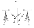
- FIG. 4 illustrates a method for transmitting and receiving a signal between a terminal located in a first cell and a base station of a neighboring cell in a mobile communication system according to an exemplary embodiment of the present invention.
- FIG. 5A is a graph illustrating the channel gain of a channel signal received from a base station of a home cell and a channel signal received from a neighboring cell measured by a terminal according to an exemplary embodiment of the present invention.
- FIG. 5B is a graph illustrating a Signal-to-Interference plus Noise Ratio (SINR) based on the measured signal strength of the channel signal received from a base station of a home cell and the measured signal strength of the channel signal received from a neighboring cell according to an exemplary embodiment of the present invention.
- SINR Signal-to-Interference plus Noise Ratio
- FIG. 6A and FIG. 6B are graphs illustrating the effect on a transmission channel when a portion of a frequency band is not used based on the signal strength of a channel signal received from a base station of a neighboring cell according to an exemplary embodiment of the present invention.
- FIG. 7 is a flowchart illustrating a method for managing uplink channel resources and reducing ICI according to an exemplary embodiment of the present invention.
- FIG. 8 is a flowchart illustrating a method for managing uplink channel resources and reducing ICI according to another exemplary embodiment of the present invention.
- FIG. 9 is a block diagram illustrating an internal configuration of a terminal according to an exemplary embodiment of the present invention.
- FIG. 4 illustrates a method for transmitting and receiving a signal between a terminal located in a first cell and a base station of a neighboring cell in a mobile communication system according to an exemplary embodiment of the present invention.
- a first terminal 421 transmits and receives data with a first base station 411 belonging to a first cell
- a second terminal 422 transmits and receives data with a second base station 412 belonging to a second cell. If the first terminal 421 is located in the first cell and transmits data to the first base station 411 of the first cell via an uplink channel, ICI may occur in a transmission signal from the second terminal 422 in the second cell to the second base station 412 of the second cell.
- a downlink signal may be received at a terminal from a base station in a neighboring cell.
- the mobile communication system may measure a downlink channel response associated with the neighboring cell by using the received downlink signal, and control the power for a particular frequency band to reduce ICI in the neighboring cell on that particular frequency band based on the measured downlink channel response. Accordingly, ICI may be reduced.
- a mobile communication system may estimate an uplink channel response based on a downlink channel response.
- a representative example of the mobile communication system includes an orthogonal frequency division multiplexing (OFDM) system based on a Time Division Duplexing (TDD) scheme.
- OFDM orthogonal frequency division multiplexing
- TDD Time Division Duplexing
- the present invention may be applicable to various systems, such as a wireless local area network (WLAN), a TDD mode of a next generation mobile communication system, which is being currently discussed in a 3 rd Generation Partnership Project Long Term Evolution (3GPP LTE) specification, a Wireless Broadband (WiBro) system, or WiBro Evolution.
- WLAN wireless local area network
- 3GPP LTE 3 rd Generation Partnership Project Long Term Evolution
- WiBro Wireless Broadband
- the present invention is not limited thereto. Specifically, the present invention may be widely applicable to systems that can measure a downlink channel response and estimate an uplink channel response. Thus, the present invention may be applicable to any types of mobile communication systems in which the downlink channel response and the uplink channel response have a certain correlation therebetween, and thus the correlation may be known in advance or measurable.
- exemplary embodiments of the present invention will be described for a mobile communication system based on an OFDM system based on a TDD scheme, which is for convenience of description, and are not limited thereto.
- the downlink channel response and the uplink channel response between the first terminal 421 located in the first cell and the second base station 412 of the second cell are identical so the correlation between downlink channel response and uplink channel response is known.
- FIG. 5A is a graph illustrating the channel gain of a channel signal received from a base station of a home cell and a channel signal received from a neighboring cell measured by a terminal according to an exemplary embodiment of the present invention.
- FIG. 5B is a graph illustrating a Signal-to-Interference plus Noise Ratio (SINR) based on the measured signal strength of the channel signal received from a base station of a home cell and the measured signal strength of the channel signal received from a neighboring cell according to an exemplary embodiment of the present invention.
- SINR Signal-to-Interference plus Noise Ratio
- FIG. 5A and FIG. 5B are graphs illustrating a downlink channel response, which may be measured by using a pilot signal received by the first terminal 421 of FIG. 4 and the second terminal 422 from the second base station 412.
- the graph 510 and graph 520 of FIG. 5A and FIG. 5B, respectively, show the downlink channel response measured for various frequency bands.
- a received channel gain 511 of the downlink channel measured by the first terminal 421 is indicated by a solid line.
- a received channel gain 512 of the downlink channel measured by the second terminal 422 is indicated by a dotted line. If the uplink channel response is identical to the downlink channel response as described above, the downlink channel response shown in the graph 510 also indicates an uplink channel response of an uplink channel in which data is transmitted from the first terminal 421 and the second terminal 422 to the second base station 412.
- a signal-to- interference plus noise ratio (SINR) 521 corresponds to a difference between gain of a transmission channel 512 and gain of an interference 511 in the second base station 412.
- the uplink channel response fluctuates very widely for each frequency band.
- SINR in a frequency band is very low if the gain of the transmission channel 512 is comparatively smaller and the gain of the interference 511 is comparatively greater.
- exemplary embodiments of the present invention disclose a method in which the first terminal 421 first measures a downlink channel response associated with the second base station 412 of the second cell for each frequency band by using a pilot signal received from the second base station 412, and does not use a frequency band with a good channel response. Thereby, the first terminal 421 may reduce ICI to the second base station 412 of the second cell.
- the pilot signal is used as an example of a signal that the first terminal 421 receives from the second base station 412 of the neighboring cell in order to measure the downlink channel response. More specifically, the first terminal 421 may receive a common pilot channel signal corresponding to a common pilot signal between neighboring cells.
- a received signal may include any type of signal that can be used to measure the downlink channel response.
- the channel response for each frequency band may be measured as channel gain of the received signal, a signal strength thereof, or a received signal power thereof.
- the channel response for each frequency band may include the above-described specific examples, and also may include various types of indexes which may be measured in a numerical value and thus comparable.
- FIG. 6A and FIG. 6B are graphs illustrating the effect on a transmission channel when a portion of a frequency band is not used based on the signal strength of a channel signal received from a base station of a neighboring cell according to an exemplary embodiment of the present invention.
- FIG. 6A and FIG. 6B are graphs illustrating a change in uplink SINR of the second base station 412 of FIG. 4 when the first terminal 421 does not use a frequency band with a good channel response for an uplink channel.
- a graph 610 shows a method for nullifying a corresponding frequency band when gain of a downlink channel 611 is greater than a threshold value 612.
- the threshold value may be uniform, such as 0 dB, for the applicable frequency band.
- frequency bands corresponding to subcarrier index values from 20 to 60, from 170 to 230, from 620 to 670, and from 850 to 1000 have a received channel gain of approximately 0 dB and therefore are not used for uplink data transmission.
- Graph 610 corresponds to channel gain 511 shown in FIG. 5A except those frequency bands greater than the threshold value of 0 dB have been nullified or adjusted down to the threshold value.
- a graph 620 shows how an uplink channel response is improved in the second base station 412 of the second cell when the frequency band with the good downlink channel is nullified.
- a portion 622 indicated by a dotted line in the graph 620, indicates the uplink SINR 521 shown in the graph 520 of FIG. 5B where channel gain 511 was not corrected for those frequency bands that exceeded 0 dB.
- another portion 621 indicated by a solid line, indicates an improved uplink SINR when the particular frequency band is nullified in graph 610 as shown in FIG. 6A according to an exemplary embodiment of the present invention.
- the SINR is significantly improved in the corresponding frequency bands. Specifically, the significant ICI may be reduced by measuring the downlink channel response associated with the second base station 412 of the second cell, and excluding the frequency band with the good channel response from the uplink channel.
- a channel response difference for each frequency band changes over time.
- an upper layer service control point (SCP) or mobile switching center (MSC) may be used.
- SCP upper layer service control point
- MSC mobile switching center
- IP ALL-Internet Protocol
- the present invention discloses a method in which each terminal measures a downlink channel response associated with a base station of a neighboring cell, and directly schedules an uplink channel resource based on the measured downlink channel response with the assumption that the downlink channel response and the uplink channel response have a certain correlation therebetween.
- the above-described conventional ICI reduction methods allocate a fixed frequency band to be used in an outer boundary of each cell and thereby reflect only long-term fading characteristics.
- short-term fading characteristics may change over time for each frequency band.
- the exemplary embodiments of the present invention consider short-term fading characteristics, and may control ICI more effectively.
- FIG. 7 is a flowchart illustrating a method for managing uplink channel resources and reducing ICI according to an exemplary embodiment of the present invention.
- a terminal receives a common pilot channel signal from a base station of a neighboring cell.
- the signal received by the terminal is not limited to the common pilot channel signal.
- the terminal measures a received signal power or strength of a downlink channel for each frequency band by using the received common pilot channel signal.
- the measured channel response for each frequency band may indicate one index of a downlink channel response.
- the channel response may be measured for each frequency band by using the signal strength of the received signal or channel gain.
- the terminal compares the measured received signal power with a predetermined threshold value, and thereby determines, selects, or adjusts a transmission signal power of an uplink channel for each frequency band based on a result of the comparison. If the received signal power for a frequency band is greater than the threshold value, the transmission signal power for that frequency band may be set to 0 watts in order to exclude the corresponding frequency band from the uplink channel. Also, it is possible to reduce the ICI in the neighboring cell by adjusting or reducing the transmission signal power of a frequency band where the received signal power is greater than the threshold value to a value less than the transmission signal power of another frequency band where the received signal power is less than or equal to the threshold value.
- the threshold value is used to determine the frequency band to be excluded from the uplink channel or to determine the transmission signal power for each frequency band.
- the threshold value may be an absolute threshold value that is equal across the available frequency band. However, depending on characteristics of the mobile communication system, the threshold value may be adjusted or variable across the available frequency band.
- the transmission signal power is then determined based on the comparison between the measured received signal power and the threshold value. Accordingly, a number of frequency bands to be excluded or to be used with a lower power may be changed based on the channel response. Specifically, in comparison to the prior art, which excludes a particular fixed frequency band from use, the present invention permits a more adaptive control over the ICI.
- the ICI to the neighboring cell may be greater. Accordingly, if a greater amount of ICI exists, a number of frequency bands having transmission signal power reduced or set to 0 watts also increases, and thus the ICI to the neighboring cell may be maintained at a lower level. Conversely, when few frequency bands have a received signal power that is greater than the threshold value, the ICI to the neighboring cell also decreases.
- a terminal may determine a number of frequency bands of which use is limited, and a location thereof. Accordingly, the terminal may adaptively manage the uplink channel resources based on a channel status.
- the terminal transmits data to the base station of the terminal's home cell via the uplink channel including frequency bands based on a transmission signal power profile for each frequency band is determined in operation S730. Also, in operation S740, the terminal may transmit the data in a diversity mode with frequency hopping among the frequency bands.
- Band-Adaptive Modulation and Coding selectively uses a particular frequency band. When a frequency band to be used in a Band-AMC based transmission mode is narrowed, or is excluded from the frequency bands allocated to a corresponding cell by considering a neighboring cell according to an exemplary embodiment of the present invention, an amount of available resources may be extremely limited. However, in the case of the diversity mode, the terminal transmits data with frequency hopping among the frequency bands. Accordingly, even though a frequency band is excluded in data transmission by considering the ICI to the neighboring cell, it may not significantly affect the entire data transmission.
- a terminal may measure a downlink channel response of a home cell by using a signal received from a base station of the home cell, and determine an uplink transmission signal power for each frequency band by additionally referring to the measured downlink channel response of the home cell.
- the transmission signal power may be determined by comparing the ratio of the received signal power of the signal, received from the neighboring base station and the home base station, with a predetermined threshold value for each frequency band.
- a transmission signal power of a frequency band where the ratio P 2 /P 1 of two received signal powers is greater than a threshold value may be set to be a value less than the transmission signal power of another frequency band where a ratio P 2 /P 1 is less than or equal to the threshold value.
- the frequency bands based on the ratio P 2 /P 1 of the received signal powers and determine the transmission signal power for each frequency band based on the arranged order.
- the ratio P 2 /P 1 ) of the received signal powers may be a weighted ratio that reflects a weight value with respect to each received signal power.
- the weight value may have a different value for each frequency band.
- the weight value to be applied to the ratio P 2 /P 1 of the received signal power for each frequency band may reflect a transmitting/receiving profile between the terminal and the base station. Specifically, a comparatively greater weight value may be assigned to a channel in which data is stably transmitted and received for more than or equal to a predetermined time.
- the terminal may determine the weight value based on weight value information received from the base station. Specifically, the base station may transmit the weight value information to which the terminal may refer when determining the weight value by considering the channel status associated with the terminal of the home cell and also the channel status associated with the terminal of the neighboring cell. Also, the terminal may determine the weight value by referring to various types of information, such as a relative location from the base station, and more specifically, a cell boundary location, and a number of terminals located in the home cell.
- the ICI to the neighboring cell may be reduced. Also, a frequency band with a good channel status may be selected. Also, when adjusting an optimum weight value, the entire system capacity may be maximized.
- the terminal may determine whether to consider the downlink channel status of the neighboring cell by first evaluating the downlink channel response of the home cell.
- FIG. 8 is a flowchart illustrating a method of managing uplink channel resources and reducing ICI according to another exemplary embodiment of the present invention.
- a terminal receives a common pilot channel signal from a base station of a home cell.
- the terminal measures a downlink channel response of the home cell by using the received signal power of the common pilot channel signal.
- the channel response of the home cell may be poor.
- the terminal may use a large number of frequency bands to improve the chance of successful data transmission. Accordingly, when the downlink channel response of the home cell is poor, data may be transmitted to the base station of the home cell by using the entire applicable frequency band in operation S830.
- Operations S840, S850, S860, and S870 shown in FIG. 8 correspond to operations S710, S720, S730, and S740 shown in FIG. 7, and thus repetitive detailed descriptions related thereto Will be omitted.
- FIG. 4 In FIG. 4, FIG. 5, FIG. 6, FIG. 7, and FIG. 8, only one neighboring cell has been described for convenience of description. However, the present invention is not limited thereto and the present invention may be applicable if more than one neighboring cell exists. Specifically, at least two neighboring cells may have ICI based on a location of the terminal in a cell. In this instance, the terminal may receive a common pilot channel signal from a base station of each neighboring cell, and determine frequency bands having limited availability for uplink data transmission by sequentially or simultaneously considering the downlink channel response of each neighboring cell.
- the terminal may select a transmission frequency band by considering only a downlink channel response of a neighboring cell that may cause significant ICI from among a plurality of neighboring cells, or may determine, reduce, adjust, or select a power of the transmission frequency band. For example, it is possible to select only a predetermined number of top frequency bands based on a received signal power of a common pilot channel signal received from a base station of each neighboring cell, or based on the mean strength of the received signal, and thereby enable the selected frequency band to control the transmission signal power of the transmission frequency band.
- the ICI reduction method and the uplink channel resource management method may be recorded in computer-readable media including program instructions to implement various operations embodied by a computer.
- the media may also include, alone or in combination with the program instructions, data files, data structures, and the like.
- Examples of computer-readable media include magnetic media such as hard disks, floppy disks, and magnetic tape; optical media such as CD ROM disks and DVD; magneto-optical media such as optical disks; and hardware devices that are specially configured to store and perform program instructions, such as read-only memory (ROM), random access memory (RAM), flash memory, and the like.
- the media may also be a transmission medium such as optical or metallic lines, wave guides, etc.
- program instructions include both machine code, such as produced by a compiler, and files containing higher level code that may be executed by the computer using an interpreter.
- the described hardware devices may be configured to act as one or more software modules in order to perform the operations of the above-described exemplary embodiments of the present invention.
- FIG. 9 is a block diagram illustrating an internal configuration of a terminal according to an exemplary embodiment of the present invention.
- the terminal includes a radio frequency (RF) module 910, a pilot signal receiver 920, a band response measurement unit 930, a band selector 940, a data transmitter 950, and a control unit 960.
- RF radio frequency
- the RF module 910 is connected to an antenna, and transmits a signal to and receives a signal from a base station via a wireless frequency band.
- the pilot signal receiver 920 extracts a pilot signal from a radio signal.
- the radio signal may be received from a base station of a neighboring cell via the RF module 910.
- the extracted pilot signal may be a common pilot channel signal.
- the band response measurement unit 930 is connected to the pilot signal receiver 920, and measures a channel response of the wireless channel by using the received pilot signal.
- the channel response is measured based on the signal strength of the pilot signal for each frequency band or channel gain. Accordingly, the entire applicable frequency band allocated to the channel may be divided into frequency bands with a good channel response and frequency bands with a poor channel response.
- the frequency bands with greater channel gain or greater received signal strength higher than a threshold value may correspond to the frequency bands with the good channel response.
- the frequency bands with the smaller channel gain or lower received signal strength lower than the threshold value may correspond to the frequency bands with the poor channel response.
- the band selector 940 selects or determines a transmission frequency band for data transmission based on the measured channel response for each frequency band.
- the data transmitter 950 transmits data to the base station of the home cell via the selected transmission frequency band.
- the band selector 940 excludes the frequency band with the good channel response from the transmission frequency band. Accordingly, the ICI may be reduced. Specifically, when carrying data in a frequency band with a good downlink channel response from the neighboring cell, and transmitting the data to the base station of the home cell, the frequency band, which may cause ICI in the neighboring cell, is excluded from the uplink data transmission. Accordingly, it is possible to reduce ICI in a neighboring cell.
- the band selector 940 may reduce the ICI amount to the neighboring cell by allocating a comparatively lower power to the frequency band with the good channel response when still using the frequency band with the good channel response for uplink data transmission.
- the pilot signal receiver 920 receives a pilot signal from the base station of the home cell so that the band response measurement unit 930 may first measure a channel response of a downlink channel for each frequency band from the base station of the home cell.
- the band selector 940 may use the entire applicable frequency band for the uplink data transmission.
- the band selector 940 may measure the downlink channel response associated with the neighboring cell, and may select a transmission frequency band for each frequency band based on the measured channel response, or may determine a transmission signal power of a corresponding frequency band.
- a channel response of a home cell is poor enough to cause ICI in a neighboring cell even though uplink data transmission to a base station of the home cell is performed by additionally considering a channel status of the home cell, it is possible to use the entire applicable frequency band without considering a channel response associated with the neighboring cell in order to reduce the risk of an unsuccessful uplink data transmission in the home cell.
- the control unit 960 transfers data to be transmitted to the base station of the home cell via the selected frequency band to the data transmitter 950. Also, the control unit 960 generates a control signal to control the configuration elements included in the terminal.
- the control unit 960 may include at least one of microprocessor, a digital signal processor (DSP), and an application specific integrated circuit (ASIC) chip for performing the functions, along with a memory to store transmission data.
- DSP digital signal processor
- ASIC application specific integrated circuit
- mobile communication terminal that is, “terminal”, used throughout the present specification includes any type of mobile communication device, such as a Personal Digital Cellular (PDC) phone, a personal communication service (PCS) phone, a personal handyphone system (PHS) phone, a Code Division Multiple Access (CDMA)-2000 (1X, 3X) phone, a Wideband CDMA phone, a dual band/dual mode phone, a Global System for Mobile Communications (GSM) phone, a mobile broadband system (MBS) phone, a Digital Multimedia Broadcasting (DMB) phone, a smart phone, and an OFDM or OFDMA communication terminal; portable terminals such as a personal digital assistant (PDA), a hand-held PC, a notebook PC, a laptop computer, a wireless broadband Internet (WiBro) terminal, an MP3 player, and an MD player; and all types of hand-held based wireless communication devices including an International Mobile Telecommunication (IMT)-2000 providing international roaming service and extended mobile communication service.
- PDC Personal Digital Cellular
- PCS personal communication
- the mobile communication terminal may include a predetermined communication module such as a CDMA module, a Bluetooth module, an Infrared Data Association (IrDA) module, a wired/wireless LAN card and a wireless communication device which is provided with a global positioning system (GPS) chip enabling tracking of a position via a GPS.
- a predetermined communication module such as a CDMA module, a Bluetooth module, an Infrared Data Association (IrDA) module, a wired/wireless LAN card and a wireless communication device which is provided with a global positioning system (GPS) chip enabling tracking of a position via a GPS.
- GPS global positioning system
- the mobile communication terminal may include a microprocessor which can play multimedia and perform a certain calculation operation, and thereby may perform calculation operation.
- the scope of the present invention includes a mobile communication system which includes a terminal constructed as described above, and a base station which transmits a signal to the terminal located in a neighboring cell, so that the terminal may measure a channel response of the signal and determine a transmission signal power for each frequency band.
- a mobile communication system is a wireless communication system based on an OFDM scheme.
- a terminal and a base station included in the mobile communication system may transmit and receive a signal based on a TDD scheme.
- a downlink channel response and an uplink channel response may be assumed to be identical to each other. Accordingly, it is possible to measure the downlink channel response by using the pilot signal received from a base station of the neighboring cell, and control signal power associated with the uplink channel by referring to the measured downlink channel response.
- the term "mobile communication system" used throughout the present specification may be widely interpreted and may indicate any type of mobile communication system in which there is a certain correlation between the downlink channel response and the uplink channel response that can be known or measured.
- the configuration of the mobile communication terminal according to an exemplary embodiment of the present invention has been described above with reference to FIG. 9.
- a configuration of a mobile communication system according to another exemplary embodiment of the present invention will be briefly described.
- the descriptions related to the ICI reduction method and the uplink resource management method, described with reference to FIG. 4, FIG. 5, FIG. 6, FIG. 7, and FIG. 8, may be applicable as is and thus further detailed descriptions related thereto will be omitted herein.
- an ICI reduction method and an uplink channel resource management method are disclosed in which a terminal can measure a channel response for each frequency band by using a base station of a neighboring cell, and determine a signal power of an uplink signal for each frequency band based on the measured channel response.
- a method for allocating a fixed frequency band to each cell which may cause an ineffective operation of wireless resources, may be eliminated and thus adaptable cell planning is enabled.
- a normal MAP it is possible to use a normal MAP. Also, a process of notifying of a location and quality of data in a frame may be simplified. Accordingly, unnecessary overhead may be eliminated and the entire system throughput may be improved.
Landscapes
- Engineering & Computer Science (AREA)
- Signal Processing (AREA)
- Computer Networks & Wireless Communication (AREA)
- Power Engineering (AREA)
- Mobile Radio Communication Systems (AREA)
Applications Claiming Priority (1)
| Application Number | Priority Date | Filing Date | Title |
|---|---|---|---|
| KR20060082991A KR100753369B1 (ko) | 2006-08-30 | 2006-08-30 | 이동통신 시스템의 셀간 간섭을 저감하는 방법 |
Publications (3)
| Publication Number | Publication Date |
|---|---|
| EP1895678A2 true EP1895678A2 (fr) | 2008-03-05 |
| EP1895678A3 EP1895678A3 (fr) | 2015-12-30 |
| EP1895678B1 EP1895678B1 (fr) | 2018-07-11 |
Family
ID=38615763
Family Applications (1)
| Application Number | Title | Priority Date | Filing Date |
|---|---|---|---|
| EP07253403.5A Active EP1895678B1 (fr) | 2006-08-30 | 2007-08-29 | Procédé pour réduction de l'interférence intercellulaire dans un système de communication mobile |
Country Status (8)
| Country | Link |
|---|---|
| US (2) | US8145252B2 (fr) |
| EP (1) | EP1895678B1 (fr) |
| JP (1) | JP4598038B2 (fr) |
| KR (1) | KR100753369B1 (fr) |
| CN (1) | CN101137237B (fr) |
| BR (1) | BRPI0703839A (fr) |
| MX (1) | MX2007010612A (fr) |
| TW (1) | TWI414188B (fr) |
Cited By (4)
| Publication number | Priority date | Publication date | Assignee | Title |
|---|---|---|---|---|
| WO2010104450A1 (fr) * | 2009-03-13 | 2010-09-16 | Telefonaktiebolaget L M Ericsson (Publ) | Contrôle des interférences intercellules dans un système de communication radio multiporteuse en liaison montante |
| CN101674641B (zh) * | 2008-09-10 | 2012-02-08 | 中兴通讯股份有限公司 | 一种基于无线通信系统下行链路小区间干扰的控制方法 |
| GB2491145A (en) * | 2011-05-25 | 2012-11-28 | Ip Wireless Inc | Reducing interference between adjacent base stations |
| EP1895795A3 (fr) * | 2006-08-30 | 2013-01-09 | Pantech Co., Ltd. | Procédé pour le contrôle d'interférence intercellulaire dans un système de communication mobile |
Families Citing this family (69)
| Publication number | Priority date | Publication date | Assignee | Title |
|---|---|---|---|---|
| KR100753369B1 (ko) | 2006-08-30 | 2007-08-30 | 주식회사 팬택 | 이동통신 시스템의 셀간 간섭을 저감하는 방법 |
| JP5333940B2 (ja) * | 2007-12-28 | 2013-11-06 | 日本電気株式会社 | 無線機、無線通信システムおよび無線電波の検出方法 |
| US8504091B2 (en) | 2008-02-01 | 2013-08-06 | Qualcomm Incorporated | Interference mitigation for control channels in a wireless communication network |
| JP5162304B2 (ja) * | 2008-04-02 | 2013-03-13 | 株式会社エヌ・ティ・ティ・ドコモ | 通信システムにおける無線通信装置及び無線通信方法 |
| US8249511B2 (en) * | 2008-06-25 | 2012-08-21 | Samsung Electronics Co., Ltd. | Downlink wireless transmission schemes with inter-cell interference mitigation |
| US8359059B2 (en) * | 2008-07-08 | 2013-01-22 | Lg Electronics Inc. | Method of controlling uplink power in wireless communication system |
| US8531975B2 (en) * | 2008-07-08 | 2013-09-10 | Lg Electronics Inc. | Method and apparatus for controlling uplink power in a wireless communication system |
| JP5160333B2 (ja) * | 2008-07-29 | 2013-03-13 | 京セラ株式会社 | 無線基地局および無線通信方法 |
| WO2010045752A1 (fr) * | 2008-10-20 | 2010-04-29 | 上海贝尔阿尔卡特股份有限公司 | Procédé de sélection de porteuse et dispositif de réglage de porteuse dans une station de base locale tdd |
| CN101742550B (zh) | 2008-11-06 | 2012-08-22 | 华为技术有限公司 | 确定影响邻小区的用户的方法、相关设备及系统 |
| JP4706879B2 (ja) * | 2008-12-26 | 2011-06-22 | 日本電気株式会社 | 無線通信システム、基地局装置、およびチャネル割当方法 |
| US8422885B2 (en) * | 2009-04-16 | 2013-04-16 | Trex Enterprises Corp | Bandwidth allocation and management system for cellular networks |
| US8086180B2 (en) * | 2009-04-21 | 2011-12-27 | Chunghwa Telecom Co., Ltd. | Method for restraining inter-cell interference in a mobile communication system |
| JP5345900B2 (ja) * | 2009-06-16 | 2013-11-20 | 株式会社エヌ・ティ・ティ・ドコモ | 無線通信システム間の周波数共用方法及び周波数共用通信システム |
| JP5345899B2 (ja) * | 2009-06-16 | 2013-11-20 | 株式会社エヌ・ティ・ティ・ドコモ | 無線通信システム間の周波数共用方法及び周波数共用通信システム |
| KR101567368B1 (ko) * | 2009-07-02 | 2015-11-09 | 삼성전자주식회사 | 광대역 무선통신 시스템에서 셀 간 간섭 감소를 위한 자원 관리 장치 및 방법 |
| KR101011289B1 (ko) * | 2009-08-04 | 2011-01-28 | 성균관대학교산학협력단 | 수신 신호 복조 방법 및 이를 수행하는 장치 |
| WO2011037215A1 (fr) * | 2009-09-24 | 2011-03-31 | 日本電気株式会社 | Station de base, station terminale, système radio, procédé de contrôle radio, et support de stockage |
| JP5508803B2 (ja) * | 2009-10-05 | 2014-06-04 | Kddi株式会社 | 送信電力制御装置、送信電力制御方法およびプログラム |
| KR101643937B1 (ko) | 2009-10-20 | 2016-08-10 | 삼성전자주식회사 | 다중 입출력 무선통신 시스템에서 셀 간 간섭을 제거하기 위한 장치 및 방법 |
| KR101819739B1 (ko) * | 2009-10-28 | 2018-01-19 | 엘지전자 주식회사 | 무선통신 시스템에서 셀간 간섭을 완화하는 장치 및 방법 |
| JP5345513B2 (ja) * | 2009-12-09 | 2013-11-20 | 京セラ株式会社 | 上位制御装置、基地局及び無線通信システム |
| KR101657125B1 (ko) * | 2009-12-10 | 2016-09-13 | 엘지전자 주식회사 | 무선 통신 시스템에서 셀간 간섭을 저감하는 방법 및 장치 |
| KR101310901B1 (ko) * | 2009-12-15 | 2013-09-25 | 한국전자통신연구원 | 셀룰러 시스템에서 전송전력 제어방법 |
| JP5711466B2 (ja) | 2010-03-08 | 2015-04-30 | 富士通株式会社 | 基地局装置および通信帯域割り当て方法 |
| CN105141391B (zh) * | 2010-03-24 | 2018-11-23 | Lg电子株式会社 | 无线电通信系统中减少小区间干扰的方法和设备 |
| WO2012045200A1 (fr) * | 2010-10-03 | 2012-04-12 | Zte Corporation | Procédé de gestion de brouillage pour surveiller une liaison radio dans un réseau hetnet |
| US9344246B2 (en) * | 2010-10-08 | 2016-05-17 | Qualcomm Incorporated | Reference signal configuration and relay downlink control channel |
| US9130725B2 (en) | 2010-11-02 | 2015-09-08 | Qualcomm Incorporated | Interaction of PDSCH resource mapping, CSI-RS, and muting |
| CN102036295B (zh) * | 2010-12-02 | 2014-04-16 | 大唐移动通信设备有限公司 | 一种确定上下行配置的方法、系统和设备 |
| GB2486494A (en) * | 2010-12-17 | 2012-06-20 | Vodafone Ip Licensing Ltd | Interference detection in mobile telecommunications networks |
| KR101196811B1 (ko) * | 2011-03-16 | 2012-11-06 | 서울대학교산학협력단 | 동적 셀간간섭 회피를 위한 방법 및 이를 위한 장치 |
| CN103493559B (zh) * | 2011-04-13 | 2017-03-15 | Lg电子株式会社 | 在无线通信系统中发送和接收用于减轻小区间干扰的信号的方法及其装置 |
| US9326151B2 (en) * | 2011-07-21 | 2016-04-26 | Telefonaktiebolaget L M Ericsson (Publ) | Methods and arrangements for a coordination of frequency band selections for interfering uplink transmissions in a cellular network |
| US9402264B2 (en) * | 2011-09-30 | 2016-07-26 | Intel Corporation | Methods to transport internet traffic over multiple wireless networks simultaneously |
| US8817685B2 (en) * | 2011-10-24 | 2014-08-26 | Nokia Corporation | Energy-efficient underlay device-to-multidevice communications with interference suppression |
| GB2496908B (en) | 2011-11-28 | 2017-04-26 | Ubiquisys Ltd | Power management in a cellular system |
| JP2013135332A (ja) * | 2011-12-26 | 2013-07-08 | Sharp Corp | 基地局装置、許容重複数決定方法、許容重複数決定プログラム、移動局装置、許容重複数通知方法及び許容重複数通知プログラム |
| WO2013129871A1 (fr) * | 2012-02-29 | 2013-09-06 | 엘지전자 주식회사 | Procédé permettant de réduire les interférences intercellulaires dans un système de communication sans fil multicellulaire coopérative, et appareil associé |
| GB2500231B (en) * | 2012-03-14 | 2014-04-30 | Broadcom Corp | Transmitter |
| JP5923786B2 (ja) * | 2012-03-16 | 2016-05-25 | シャープ株式会社 | 基地局装置及び通信方法 |
| WO2013144950A1 (fr) | 2012-03-25 | 2013-10-03 | Intucell Ltd. | Système et procédé d'optimisation de performances d'un réseau de communication |
| US9215663B2 (en) * | 2012-06-29 | 2015-12-15 | Qualcomm Incorporated | Methods and devices for controlling uplink transmit power at an access terminal |
| US9843429B2 (en) | 2012-07-31 | 2017-12-12 | Lg Electronics Inc. | Method and apparatus for transmitting and receiving data |
| US8923851B2 (en) * | 2012-09-07 | 2014-12-30 | Symbol Technologies, Inc. | System and method for roaming band preference |
| IL222709A (en) | 2012-10-25 | 2016-02-29 | Intucell Ltd | A method and mechanism for coordinating interference between communications cells in solar systems |
| US8918136B2 (en) * | 2012-11-29 | 2014-12-23 | At&T Mobility Ii Llc | Adjustment of transmit power parameter |
| US9167444B2 (en) | 2012-12-04 | 2015-10-20 | Cisco Technology, Inc. | Method for managing heterogeneous cellular networks |
| IL224926A0 (en) | 2013-02-26 | 2013-07-31 | Valdimir Yanover | A method and system for allocating resources in the @telecommunications@cellphone network |
| GB2518584B (en) | 2013-07-09 | 2019-12-25 | Cisco Tech Inc | Power setting |
| CN103957532B (zh) * | 2014-04-15 | 2017-06-27 | 电子科技大学 | 一种提高异构蜂窝网络能效的方法 |
| US9655102B2 (en) | 2014-06-20 | 2017-05-16 | Cisco Technology, Inc. | Interference control in a cellular communications network |
| US9918314B2 (en) | 2015-04-14 | 2018-03-13 | Cisco Technology, Inc. | System and method for providing uplink inter cell interference coordination in a network environment |
| US9860852B2 (en) | 2015-07-25 | 2018-01-02 | Cisco Technology, Inc. | System and method to facilitate small cell uplink power control in a network environment |
| US9648569B2 (en) | 2015-07-25 | 2017-05-09 | Cisco Technology, Inc. | System and method to facilitate small cell uplink power control in a network environment |
| US9854535B2 (en) | 2015-07-28 | 2017-12-26 | Cisco Technology, Inc. | Determining fractional frequency reuse power levels for downlink transmissions |
| US9854536B2 (en) | 2015-08-03 | 2017-12-26 | Cisco Technology, Inc. | User equipment power level selection for downlink transmissions |
| US9848389B2 (en) | 2015-08-03 | 2017-12-19 | Cisco Technology, Inc. | Selecting cells for downlink inter-cell interference coordination |
| US10154415B2 (en) | 2015-08-04 | 2018-12-11 | Cisco Technology, Inc. | Resource adaptation for frequency domain downlink inter-cell interference coordination |
| US9967067B2 (en) | 2015-09-08 | 2018-05-08 | Cisco Technology, Inc. | Serving noise/macro interference limited user equipment for downlink inter-cell interference coordination |
| US9820296B2 (en) | 2015-10-20 | 2017-11-14 | Cisco Technology, Inc. | System and method for frequency and time domain downlink inter-cell interference coordination |
| US9826408B2 (en) | 2015-12-07 | 2017-11-21 | Cisco Technology, Inc. | System and method to provide uplink interference coordination in a network environment |
| US10143002B2 (en) | 2016-01-12 | 2018-11-27 | Cisco Technology, Inc. | System and method to facilitate centralized radio resource management in a split radio access network environment |
| US9813970B2 (en) | 2016-01-20 | 2017-11-07 | Cisco Technology, Inc. | System and method to provide small cell power control and load balancing for high mobility user equipment in a network environment |
| US10091697B1 (en) | 2016-02-08 | 2018-10-02 | Cisco Technology, Inc. | Mitigation of uplink interference within heterogeneous wireless communications networks |
| US10396926B2 (en) * | 2016-08-19 | 2019-08-27 | Samsung Electronics Co., Ltd. | Apparatus and method for suppressing inter-cell interference in wireless communication system |
| CN107769883B (zh) * | 2016-08-19 | 2021-10-29 | 北京三星通信技术研究有限公司 | 一种小区间干扰抑制的方法及设备 |
| US20180124700A1 (en) * | 2016-11-01 | 2018-05-03 | Qualcomm Incorporated | Transmit power configuration based on bandwidth |
| KR101901902B1 (ko) * | 2016-12-22 | 2018-11-13 | 한양대학교 산학협력단 | 이동통신 중계 장치 및 그 전력 증폭 이득 자동 설정 방법 |
Family Cites Families (59)
| Publication number | Priority date | Publication date | Assignee | Title |
|---|---|---|---|---|
| JPH08107382A (ja) | 1994-10-05 | 1996-04-23 | Tec Corp | 無線通信システム |
| WO1998053558A2 (fr) * | 1997-05-22 | 1998-11-26 | Siemens Aktiengesellschaft | Procede et dispositif de regulation de la puissance d'emission pour des liaisons entre une station de base et des stations mobiles d'un systeme de radiocommunication |
| JP3355295B2 (ja) * | 1997-11-13 | 2002-12-09 | 松下電器産業株式会社 | 送信電力制御方法及び送受信装置 |
| JP3013822B2 (ja) | 1997-11-20 | 2000-02-28 | 日本電気株式会社 | スペクトラム拡散通信システム |
| US6708041B1 (en) | 1997-12-15 | 2004-03-16 | Telefonaktiebolaget Lm (Publ) | Base station transmit power control in a CDMA cellular telephone system |
| CA2288682C (fr) * | 1998-03-26 | 2003-04-15 | Samsung Electronics Co., Ltd. | Dispositif et procede de commande de puissances d'un canal orthogonal et d'un canal quasi-orthogonal dans un systeme de telecommunications amdc |
| JP3109504B2 (ja) | 1998-03-27 | 2000-11-20 | 日本電気株式会社 | セルラシステムおよびセルラシステムの隣接周波数干渉回避方法と移動局 |
| JP3957882B2 (ja) | 1998-06-17 | 2007-08-15 | 株式会社日立コミュニケーションテクノロジー | 電力制御方法及び電力制御装置 |
| KR20000013025A (ko) * | 1998-08-01 | 2000-03-06 | 윤종용 | 이동통신 시스템의 순방향 초기 송신전력 제어장치 및 방법 |
| KR100433910B1 (ko) * | 1999-02-13 | 2004-06-04 | 삼성전자주식회사 | 부호분할다중접속 통신시스템의 주파수간핸드오프를 위한 전력 |
| GB9906005D0 (en) * | 1999-03-17 | 1999-05-12 | Motorola Ltd | A subscriber unit and method of cell selection for a cellular communication system |
| JP2001204075A (ja) * | 2000-01-24 | 2001-07-27 | Kddi Corp | 無線パケットチャネルを動的に割り当てる移動通信システム |
| FR2808158B1 (fr) | 2000-04-19 | 2002-06-07 | Mitsubishi Electric Inf Tech | Methode de controle de puissance dans un systeme de telecommunication |
| JP3438703B2 (ja) * | 2000-06-28 | 2003-08-18 | 日本電気株式会社 | スペクトラム拡散通信装置及びその通信方法 |
| US7233810B2 (en) * | 2000-08-03 | 2007-06-19 | Infineon Technologies Ag | Dynamically reconfigurable universal transmitter system |
| CN1162997C (zh) * | 2000-10-04 | 2004-08-18 | 三星电子株式会社 | 用于移动通信系统中下行链路共享信道的功率控制的装置和方法 |
| US6947748B2 (en) * | 2000-12-15 | 2005-09-20 | Adaptix, Inc. | OFDMA with adaptive subcarrier-cluster configuration and selective loading |
| TW545003B (en) * | 2001-01-16 | 2003-08-01 | Matsushita Electric Industrial Co Ltd | Antenna diversity communications device |
| US6801767B1 (en) * | 2001-01-26 | 2004-10-05 | Lgc Wireless, Inc. | Method and system for distributing multiband wireless communications signals |
| US7151740B2 (en) | 2001-02-28 | 2006-12-19 | Cingular Wireless Ii, Llc | Transmit power control for an OFDM-based wireless communication system |
| US6934340B1 (en) | 2001-03-19 | 2005-08-23 | Cisco Technology, Inc. | Adaptive control system for interference rejections in a wireless communications system |
| US7020110B2 (en) * | 2002-01-08 | 2006-03-28 | Qualcomm Incorporated | Resource allocation for MIMO-OFDM communication systems |
| US6794858B2 (en) | 2002-03-07 | 2004-09-21 | Hitachi Kokusai Electric Inc. | Receiving level measuring circuit |
| US20040013101A1 (en) | 2002-05-23 | 2004-01-22 | Akin Huseyin C. | Method and system for allocating power and scheduling packets in one or more cells of a wireless communication system or network |
| JP4150239B2 (ja) | 2002-10-03 | 2008-09-17 | 株式会社エヌ・ティ・ティ・ドコモ | 移動通信システム、基地局、移動局、及びセル制御方法 |
| JP4027816B2 (ja) * | 2003-02-13 | 2007-12-26 | 株式会社エヌ・ティ・ティ・ドコモ | 移動通信システム、これに用いて好適な無線局、移動局及び下り送信電力制御方法 |
| JP4178055B2 (ja) | 2003-02-25 | 2008-11-12 | 株式会社エヌ・ティ・ティ・ドコモ | 無線パケット通信システム、無線パケット通信方法、基地局及び移動局 |
| KR100477471B1 (ko) * | 2003-05-13 | 2005-03-17 | 한국전자통신연구원 | 고속 무선 통신에서의 다중 접속 방법 |
| US7333813B2 (en) * | 2003-06-10 | 2008-02-19 | Lucent Technologies Inc. | Methods and devices for assigning mobile devices to base stations in the presence of interference |
| JP2005020566A (ja) | 2003-06-27 | 2005-01-20 | Toshiba Corp | 基地局装置、移動端末、および通信方法 |
| DE60303031T2 (de) | 2003-08-21 | 2006-08-31 | France Telecom | Verfahren und System zur Bewertung von Störungen zwischen Zellen in der Aufwärtsrichtung |
| CN1802862A (zh) | 2003-08-27 | 2006-07-12 | 富士通株式会社 | 切换方法以及基站控制装置 |
| EP1530387A1 (fr) | 2003-11-06 | 2005-05-11 | Matsushita Electric Industrial Co., Ltd. | Réglage de la puissance d'émission pendant l'affectation de canaux pour la répartition d'interférences dans un système cellulaire de communication mobile |
| KR100534594B1 (ko) * | 2003-12-27 | 2005-12-07 | 한국전자통신연구원 | 다중반송파 코드분할다중접속 시스템에서 적응형 하향링크패킷 전송방법 |
| JP2005267095A (ja) | 2004-03-17 | 2005-09-29 | Nippon Telegr & Teleph Corp <Ntt> | 情報表示方法及び装置及び情報表示プログラム |
| EP1589776A1 (fr) | 2004-04-19 | 2005-10-26 | Telefonaktiebolaget LM Ericsson (publ) | Attribution dynamique de ressources radio |
| JP2005318327A (ja) | 2004-04-28 | 2005-11-10 | Matsushita Electric Ind Co Ltd | 通信端末装置及び送信電力制御方法 |
| DE602004011479T2 (de) * | 2004-05-04 | 2009-02-05 | Alcatel Lucent | Verfahren zur Interzell-Interferenzskoordination mit Leistungsplanung in einem OFDM-Mobilkommunikationssystem |
| US8085831B2 (en) | 2004-05-17 | 2011-12-27 | Qualcomm Incorporated | Interference control via selective blanking/attenuation of interfering transmissions |
| US8452316B2 (en) | 2004-06-18 | 2013-05-28 | Qualcomm Incorporated | Power control for a wireless communication system utilizing orthogonal multiplexing |
| US20050286547A1 (en) * | 2004-06-24 | 2005-12-29 | Baum Kevin L | Method and apparatus for accessing a wireless multi-carrier communication system |
| WO2006004968A2 (fr) | 2004-06-30 | 2006-01-12 | Neocific, Inc. | Procedes et appareil de commande de puissance dans des systemes sans fil multiporteuse |
| TWI288572B (en) * | 2004-08-04 | 2007-10-11 | Benq Corp | Mobile unit and method for which to re-select a serving base station |
| KR100974326B1 (ko) | 2004-10-28 | 2010-08-05 | 삼성전자주식회사 | 직교 주파수 분할 다중 접속 방식을 사용하는 통신시스템에서 동적 자원 할당 장치 및 방법 |
| KR20060038131A (ko) * | 2004-10-29 | 2006-05-03 | 삼성전자주식회사 | Fh-ofdma 방식을 사용하는 통신 시스템에서상향링크 스케줄링 방법 |
| KR100790115B1 (ko) * | 2004-10-29 | 2007-12-31 | 삼성전자주식회사 | 통신 시스템에서 적응적 안테나 시스템을 위한 프리앰블 시퀀스 송신 전력 제어 장치 및 방법 |
| KR100612045B1 (ko) | 2004-12-08 | 2006-08-14 | 한국전자통신연구원 | 인접 셀 간의 간섭을 억제하기 위한 기지국 제어 방법 |
| JP4484062B2 (ja) * | 2005-02-14 | 2010-06-16 | 日本電気株式会社 | Cdma基地局装置および上り送信電力制御方法 |
| DE602005015721D1 (de) | 2005-06-15 | 2009-09-10 | Alcatel Lucent | Verfahren zur Aufwärtsinterferenzkoordinierung in Monofrequenznetzen, Basisstation und Mobilnetz dafür |
| EP1897245A4 (fr) | 2005-06-20 | 2013-01-16 | Texas Instruments Inc | Commande d'alimentation electrique de liaison montante lente |
| US20070046459A1 (en) * | 2005-08-31 | 2007-03-01 | Motorola, Inc. | Methods and apparatus for asset tracking |
| US7873327B2 (en) * | 2006-08-22 | 2011-01-18 | Alcatel-Lucent Usa Inc. | Method for adaptively controlling other cell interference |
| KR100753369B1 (ko) | 2006-08-30 | 2007-08-30 | 주식회사 팬택 | 이동통신 시스템의 셀간 간섭을 저감하는 방법 |
| KR100765892B1 (ko) * | 2006-08-30 | 2007-10-10 | 주식회사 팬택 | 이동통신 시스템의 셀간 간섭을 제어하는 방법 |
| KR100991792B1 (ko) | 2007-12-31 | 2010-11-04 | 엘지전자 주식회사 | 협력적 다중 입출력 방식 신호 송수신 방법 |
| US8126403B2 (en) | 2008-04-23 | 2012-02-28 | Telefonaktiebolaget Lm Ericsson (Publ) | Estimating and limiting inter-cell interference |
| JP5085481B2 (ja) | 2008-09-22 | 2012-11-28 | 株式会社エヌ・ティ・ティ・ドコモ | 送信電力制御方法、移動通信システム及び無線基地局 |
| US8145223B2 (en) | 2009-04-09 | 2012-03-27 | Telefonaktiebolaget L M Ericsson (Publ) | Inter-cell interference mitigation |
| US9749965B2 (en) | 2010-11-02 | 2017-08-29 | Telefonaktiebolaget L M Ericsson | Method for uplink fractional transmit power control |
-
2006
- 2006-08-30 KR KR20060082991A patent/KR100753369B1/ko active Active
-
2007
- 2007-08-28 US US11/846,106 patent/US8145252B2/en active Active
- 2007-08-28 BR BRPI0703839-9A patent/BRPI0703839A/pt not_active IP Right Cessation
- 2007-08-29 EP EP07253403.5A patent/EP1895678B1/fr active Active
- 2007-08-29 TW TW96132057A patent/TWI414188B/zh active
- 2007-08-30 CN CN2007101471990A patent/CN101137237B/zh active Active
- 2007-08-30 JP JP2007223592A patent/JP4598038B2/ja active Active
- 2007-08-30 MX MX2007010612A patent/MX2007010612A/es active IP Right Grant
-
2012
- 2012-03-06 US US13/412,933 patent/US9167534B2/en active Active
Cited By (6)
| Publication number | Priority date | Publication date | Assignee | Title |
|---|---|---|---|---|
| EP1895795A3 (fr) * | 2006-08-30 | 2013-01-09 | Pantech Co., Ltd. | Procédé pour le contrôle d'interférence intercellulaire dans un système de communication mobile |
| CN101674641B (zh) * | 2008-09-10 | 2012-02-08 | 中兴通讯股份有限公司 | 一种基于无线通信系统下行链路小区间干扰的控制方法 |
| WO2010104450A1 (fr) * | 2009-03-13 | 2010-09-16 | Telefonaktiebolaget L M Ericsson (Publ) | Contrôle des interférences intercellules dans un système de communication radio multiporteuse en liaison montante |
| US8385832B2 (en) | 2009-03-13 | 2013-02-26 | Telefonaktiebolaget Lm Ericsson (Publ) | Inter-cell interference control in an uplink multi-carrier radio communications system |
| GB2491145A (en) * | 2011-05-25 | 2012-11-28 | Ip Wireless Inc | Reducing interference between adjacent base stations |
| GB2491145B (en) * | 2011-05-25 | 2014-02-26 | Intellectual Ventures Holding 81 Llc | Wireless network element integrated circuit and method for reducing interference |
Also Published As
| Publication number | Publication date |
|---|---|
| MX2007010612A (es) | 2009-02-04 |
| TW200818953A (en) | 2008-04-16 |
| KR100753369B1 (ko) | 2007-08-30 |
| EP1895678B1 (fr) | 2018-07-11 |
| TWI414188B (zh) | 2013-11-01 |
| CN101137237B (zh) | 2011-05-11 |
| EP1895678A3 (fr) | 2015-12-30 |
| US9167534B2 (en) | 2015-10-20 |
| BRPI0703839A (pt) | 2008-04-22 |
| CN101137237A (zh) | 2008-03-05 |
| JP4598038B2 (ja) | 2010-12-15 |
| JP2008061249A (ja) | 2008-03-13 |
| US20120163228A1 (en) | 2012-06-28 |
| US8145252B2 (en) | 2012-03-27 |
| US20080057996A1 (en) | 2008-03-06 |
Similar Documents
| Publication | Publication Date | Title |
|---|---|---|
| EP1895678B1 (fr) | Procédé pour réduction de l'interférence intercellulaire dans un système de communication mobile | |
| US8433350B2 (en) | Method for controlling inter-cell interference in a mobile communication system | |
| US8588178B2 (en) | Adaptive association and joint association and resource partitioning in a wireless communication network | |
| US8023529B2 (en) | System and method for using resources in a communication system | |
| KR101208397B1 (ko) | 서빙 섹터 전력 제어 | |
| KR101120643B1 (ko) | 가상섹터 기반 적응적 안테나시스템의 공간분할다중접속 서비스방법 | |
| WO2008003815A1 (fr) | Mécanisme d'attribution de ressources radio amélioré | |
| TW200934262A (en) | A method and a mobile station for providing an interference measurement result, a method for configuring radio resource allocation, a method for scheduling a mobile station, and a cellular orthogonal frequency division multiple access system | |
| KR20090026896A (ko) | 부분 주파수 재사용을 기반으로 하는 이동통신 시스템에서전송전력 제어방법 및 장치 | |
| KR100959336B1 (ko) | 광대역 무선 통신시스템에서 인접 셀 간섭을 줄이기 위한장치 및 방법 | |
| US20090163222A1 (en) | Method for performing resource allocation in a wireless communication network, base station and wireless communication network | |
| KR101335363B1 (ko) | 무선 통신 시스템에서 주파수 할당 방법 | |
| US8213335B2 (en) | Communication resource allocation method of base station | |
| CN100525158C (zh) | 时分双工码分多址系统中使用交叉时隙资源的方法及装置 | |
| EP2816854A1 (fr) | Equilibrage de charge entre antennes et ordonnancement pour l'amélioration du débit des utilisateurs en bord de cellule | |
| Lengoumbi et al. | Dynamic subcarrier reuse with rate guaranty in a downlink multicell OFDMA system |
Legal Events
| Date | Code | Title | Description |
|---|---|---|---|
| PUAI | Public reference made under article 153(3) epc to a published international application that has entered the european phase |
Free format text: ORIGINAL CODE: 0009012 |
|
| 17P | Request for examination filed |
Effective date: 20070917 |
|
| AK | Designated contracting states |
Kind code of ref document: A2 Designated state(s): AT BE BG CH CY CZ DE DK EE ES FI FR GB GR HU IE IS IT LI LT LU LV MC MT NL PL PT RO SE SI SK TR |
|
| AX | Request for extension of the european patent |
Extension state: AL BA HR MK YU |
|
| PUAL | Search report despatched |
Free format text: ORIGINAL CODE: 0009013 |
|
| AK | Designated contracting states |
Kind code of ref document: A3 Designated state(s): AT BE BG CH CY CZ DE DK EE ES FI FR GB GR HU IE IS IT LI LT LU LV MC MT NL PL PT RO SE SI SK TR |
|
| AX | Request for extension of the european patent |
Extension state: AL BA HR MK RS |
|
| AKY | No designation fees paid | ||
| AXX | Extension fees paid |
Extension state: BA Extension state: HR Extension state: MK Extension state: AL Extension state: RS |
|
| REG | Reference to a national code |
Ref country code: DE Ref legal event code: R108 Ref document number: 602007055321 Country of ref document: DE Ref country code: DE Ref legal event code: R108 |
|
| RBV | Designated contracting states (corrected) |
Designated state(s): AT BE BG CH CY CZ DE DK EE ES FI FR GB GR HU IE IS IT LI LT LU LV MC MT NL PL PT RO SE SI SK TR |
|
| 19U | Interruption of proceedings before grant |
Effective date: 20160317 |
|
| 19W | Proceedings resumed before grant after interruption of proceedings |
Effective date: 20170301 |
|
| RAP1 | Party data changed (applicant data changed or rights of an application transferred) |
Owner name: PANTECH INC. |
|
| 17Q | First examination report despatched |
Effective date: 20170530 |
|
| RAP1 | Party data changed (applicant data changed or rights of an application transferred) |
Owner name: GOLDPEAK INNOVATIONS INC. |
|
| REG | Reference to a national code |
Ref country code: DE Ref legal event code: R079 Ref document number: 602007055321 Country of ref document: DE Free format text: PREVIOUS MAIN CLASS: H04B0007005000 Ipc: H04W0052140000 |
|
| RIC1 | Information provided on ipc code assigned before grant |
Ipc: H04W 52/14 20090101AFI20171215BHEP Ipc: H04W 52/24 20090101ALI20171215BHEP |
|
| GRAP | Despatch of communication of intention to grant a patent |
Free format text: ORIGINAL CODE: EPIDOSNIGR1 |
|
| INTG | Intention to grant announced |
Effective date: 20180205 |
|
| GRAS | Grant fee paid |
Free format text: ORIGINAL CODE: EPIDOSNIGR3 |
|
| GRAA | (expected) grant |
Free format text: ORIGINAL CODE: 0009210 |
|
| AK | Designated contracting states |
Kind code of ref document: B1 Designated state(s): AT BE BG CH CY CZ DE DK EE ES FI FR GB GR HU IE IS IT LI LT LU LV MC MT NL PL PT RO SE SI SK TR |
|
| RAP1 | Party data changed (applicant data changed or rights of an application transferred) |
Owner name: GOLDPEAK INNOVATIONS INC. |
|
| REG | Reference to a national code |
Ref country code: GB Ref legal event code: FG4D |
|
| REG | Reference to a national code |
Ref country code: CH Ref legal event code: EP |
|
| REG | Reference to a national code |
Ref country code: AT Ref legal event code: REF Ref document number: 1018268 Country of ref document: AT Kind code of ref document: T Effective date: 20180715 |
|
| REG | Reference to a national code |
Ref country code: IE Ref legal event code: FG4D |
|
| REG | Reference to a national code |
Ref country code: DE Ref legal event code: R096 Ref document number: 602007055321 Country of ref document: DE |
|
| REG | Reference to a national code |
Ref country code: FR Ref legal event code: PLFP Year of fee payment: 12 |
|
| REG | Reference to a national code |
Ref country code: NL Ref legal event code: MP Effective date: 20180711 |
|
| REG | Reference to a national code |
Ref country code: LT Ref legal event code: MG4D |
|
| REG | Reference to a national code |
Ref country code: AT Ref legal event code: MK05 Ref document number: 1018268 Country of ref document: AT Kind code of ref document: T Effective date: 20180711 |
|
| PG25 | Lapsed in a contracting state [announced via postgrant information from national office to epo] |
Ref country code: NL Free format text: LAPSE BECAUSE OF FAILURE TO SUBMIT A TRANSLATION OF THE DESCRIPTION OR TO PAY THE FEE WITHIN THE PRESCRIBED TIME-LIMIT Effective date: 20180711 |
|
| PG25 | Lapsed in a contracting state [announced via postgrant information from national office to epo] |
Ref country code: SE Free format text: LAPSE BECAUSE OF FAILURE TO SUBMIT A TRANSLATION OF THE DESCRIPTION OR TO PAY THE FEE WITHIN THE PRESCRIBED TIME-LIMIT Effective date: 20180711 Ref country code: PL Free format text: LAPSE BECAUSE OF FAILURE TO SUBMIT A TRANSLATION OF THE DESCRIPTION OR TO PAY THE FEE WITHIN THE PRESCRIBED TIME-LIMIT Effective date: 20180711 Ref country code: LT Free format text: LAPSE BECAUSE OF FAILURE TO SUBMIT A TRANSLATION OF THE DESCRIPTION OR TO PAY THE FEE WITHIN THE PRESCRIBED TIME-LIMIT Effective date: 20180711 Ref country code: FI Free format text: LAPSE BECAUSE OF FAILURE TO SUBMIT A TRANSLATION OF THE DESCRIPTION OR TO PAY THE FEE WITHIN THE PRESCRIBED TIME-LIMIT Effective date: 20180711 Ref country code: BG Free format text: LAPSE BECAUSE OF FAILURE TO SUBMIT A TRANSLATION OF THE DESCRIPTION OR TO PAY THE FEE WITHIN THE PRESCRIBED TIME-LIMIT Effective date: 20181011 Ref country code: GR Free format text: LAPSE BECAUSE OF FAILURE TO SUBMIT A TRANSLATION OF THE DESCRIPTION OR TO PAY THE FEE WITHIN THE PRESCRIBED TIME-LIMIT Effective date: 20181012 Ref country code: IS Free format text: LAPSE BECAUSE OF FAILURE TO SUBMIT A TRANSLATION OF THE DESCRIPTION OR TO PAY THE FEE WITHIN THE PRESCRIBED TIME-LIMIT Effective date: 20181111 Ref country code: AT Free format text: LAPSE BECAUSE OF FAILURE TO SUBMIT A TRANSLATION OF THE DESCRIPTION OR TO PAY THE FEE WITHIN THE PRESCRIBED TIME-LIMIT Effective date: 20180711 |
|
| REG | Reference to a national code |
Ref country code: CH Ref legal event code: PK Free format text: BERICHTIGUNGEN |
|
| RIC2 | Information provided on ipc code assigned after grant |
Ipc: H04W 52/14 20090101AFI20171215BHEP Ipc: H04W 52/24 20090101ALI20171215BHEP |
|
| PG25 | Lapsed in a contracting state [announced via postgrant information from national office to epo] |
Ref country code: ES Free format text: LAPSE BECAUSE OF FAILURE TO SUBMIT A TRANSLATION OF THE DESCRIPTION OR TO PAY THE FEE WITHIN THE PRESCRIBED TIME-LIMIT Effective date: 20180711 Ref country code: LV Free format text: LAPSE BECAUSE OF FAILURE TO SUBMIT A TRANSLATION OF THE DESCRIPTION OR TO PAY THE FEE WITHIN THE PRESCRIBED TIME-LIMIT Effective date: 20180711 |
|
| REG | Reference to a national code |
Ref country code: CH Ref legal event code: PL |
|
| REG | Reference to a national code |
Ref country code: DE Ref legal event code: R097 Ref document number: 602007055321 Country of ref document: DE |
|
| PG25 | Lapsed in a contracting state [announced via postgrant information from national office to epo] |
Ref country code: EE Free format text: LAPSE BECAUSE OF FAILURE TO SUBMIT A TRANSLATION OF THE DESCRIPTION OR TO PAY THE FEE WITHIN THE PRESCRIBED TIME-LIMIT Effective date: 20180711 Ref country code: RO Free format text: LAPSE BECAUSE OF FAILURE TO SUBMIT A TRANSLATION OF THE DESCRIPTION OR TO PAY THE FEE WITHIN THE PRESCRIBED TIME-LIMIT Effective date: 20180711 Ref country code: LU Free format text: LAPSE BECAUSE OF NON-PAYMENT OF DUE FEES Effective date: 20180829 Ref country code: CH Free format text: LAPSE BECAUSE OF NON-PAYMENT OF DUE FEES Effective date: 20180831 Ref country code: CZ Free format text: LAPSE BECAUSE OF FAILURE TO SUBMIT A TRANSLATION OF THE DESCRIPTION OR TO PAY THE FEE WITHIN THE PRESCRIBED TIME-LIMIT Effective date: 20180711 Ref country code: IT Free format text: LAPSE BECAUSE OF FAILURE TO SUBMIT A TRANSLATION OF THE DESCRIPTION OR TO PAY THE FEE WITHIN THE PRESCRIBED TIME-LIMIT Effective date: 20180711 Ref country code: MC Free format text: LAPSE BECAUSE OF FAILURE TO SUBMIT A TRANSLATION OF THE DESCRIPTION OR TO PAY THE FEE WITHIN THE PRESCRIBED TIME-LIMIT Effective date: 20180711 Ref country code: LI Free format text: LAPSE BECAUSE OF NON-PAYMENT OF DUE FEES Effective date: 20180831 |
|
| REG | Reference to a national code |
Ref country code: BE Ref legal event code: MM Effective date: 20180831 |
|
| PLBE | No opposition filed within time limit |
Free format text: ORIGINAL CODE: 0009261 |
|
| STAA | Information on the status of an ep patent application or granted ep patent |
Free format text: STATUS: NO OPPOSITION FILED WITHIN TIME LIMIT |
|
| PG25 | Lapsed in a contracting state [announced via postgrant information from national office to epo] |
Ref country code: SK Free format text: LAPSE BECAUSE OF FAILURE TO SUBMIT A TRANSLATION OF THE DESCRIPTION OR TO PAY THE FEE WITHIN THE PRESCRIBED TIME-LIMIT Effective date: 20180711 Ref country code: DK Free format text: LAPSE BECAUSE OF FAILURE TO SUBMIT A TRANSLATION OF THE DESCRIPTION OR TO PAY THE FEE WITHIN THE PRESCRIBED TIME-LIMIT Effective date: 20180711 |
|
| 26N | No opposition filed |
Effective date: 20190412 |
|
| PG25 | Lapsed in a contracting state [announced via postgrant information from national office to epo] |
Ref country code: SI Free format text: LAPSE BECAUSE OF FAILURE TO SUBMIT A TRANSLATION OF THE DESCRIPTION OR TO PAY THE FEE WITHIN THE PRESCRIBED TIME-LIMIT Effective date: 20180711 Ref country code: BE Free format text: LAPSE BECAUSE OF NON-PAYMENT OF DUE FEES Effective date: 20180831 |
|
| PG25 | Lapsed in a contracting state [announced via postgrant information from national office to epo] |
Ref country code: MT Free format text: LAPSE BECAUSE OF NON-PAYMENT OF DUE FEES Effective date: 20180829 |
|
| PG25 | Lapsed in a contracting state [announced via postgrant information from national office to epo] |
Ref country code: TR Free format text: LAPSE BECAUSE OF FAILURE TO SUBMIT A TRANSLATION OF THE DESCRIPTION OR TO PAY THE FEE WITHIN THE PRESCRIBED TIME-LIMIT Effective date: 20180711 |
|
| REG | Reference to a national code |
Ref country code: DE Ref legal event code: R082 Ref document number: 602007055321 Country of ref document: DE Representative=s name: BETTEN & RESCH PATENT- UND RECHTSANWAELTE PART, DE Ref country code: DE Ref legal event code: R081 Ref document number: 602007055321 Country of ref document: DE Owner name: PANTECH CORPORATION, KR Free format text: FORMER OWNER: GOLDPEAK INNOVATIONS INC., SEOUL, KR |
|
| PG25 | Lapsed in a contracting state [announced via postgrant information from national office to epo] |
Ref country code: HU Free format text: LAPSE BECAUSE OF FAILURE TO SUBMIT A TRANSLATION OF THE DESCRIPTION OR TO PAY THE FEE WITHIN THE PRESCRIBED TIME-LIMIT; INVALID AB INITIO Effective date: 20070829 Ref country code: PT Free format text: LAPSE BECAUSE OF FAILURE TO SUBMIT A TRANSLATION OF THE DESCRIPTION OR TO PAY THE FEE WITHIN THE PRESCRIBED TIME-LIMIT Effective date: 20180711 |
|
| PG25 | Lapsed in a contracting state [announced via postgrant information from national office to epo] |
Ref country code: IE Free format text: LAPSE BECAUSE OF NON-PAYMENT OF DUE FEES Effective date: 20180829 Ref country code: CY Free format text: LAPSE BECAUSE OF FAILURE TO SUBMIT A TRANSLATION OF THE DESCRIPTION OR TO PAY THE FEE WITHIN THE PRESCRIBED TIME-LIMIT Effective date: 20180711 |
|
| REG | Reference to a national code |
Ref country code: GB Ref legal event code: 732E Free format text: REGISTERED BETWEEN 20200625 AND 20200701 |
|
| P01 | Opt-out of the competence of the unified patent court (upc) registered |
Effective date: 20230518 |
|
| PGFP | Annual fee paid to national office [announced via postgrant information from national office to epo] |
Ref country code: GB Payment date: 20250610 Year of fee payment: 19 |
|
| PGFP | Annual fee paid to national office [announced via postgrant information from national office to epo] |
Ref country code: FR Payment date: 20250611 Year of fee payment: 19 |
|
| PGFP | Annual fee paid to national office [announced via postgrant information from national office to epo] |
Ref country code: DE Payment date: 20250609 Year of fee payment: 19 |