EP1896164B1 - Vorrichtung zur mischung eines flüssigmediums - Google Patents
Vorrichtung zur mischung eines flüssigmediums Download PDFInfo
- Publication number
- EP1896164B1 EP1896164B1 EP06765779A EP06765779A EP1896164B1 EP 1896164 B1 EP1896164 B1 EP 1896164B1 EP 06765779 A EP06765779 A EP 06765779A EP 06765779 A EP06765779 A EP 06765779A EP 1896164 B1 EP1896164 B1 EP 1896164B1
- Authority
- EP
- European Patent Office
- Prior art keywords
- membrane
- mixing
- actuation
- foil
- inclination
- Prior art date
- Legal status (The legal status is an assumption and is not a legal conclusion. Google has not performed a legal analysis and makes no representation as to the accuracy of the status listed.)
- Not-in-force
Links
Images

Classifications
-
- B—PERFORMING OPERATIONS; TRANSPORTING
- B01—PHYSICAL OR CHEMICAL PROCESSES OR APPARATUS IN GENERAL
- B01F—MIXING, e.g. DISSOLVING, EMULSIFYING OR DISPERSING
- B01F33/00—Other mixers; Mixing plants; Combinations of mixers
- B01F33/30—Micromixers
-
- B—PERFORMING OPERATIONS; TRANSPORTING
- B01—PHYSICAL OR CHEMICAL PROCESSES OR APPARATUS IN GENERAL
- B01F—MIXING, e.g. DISSOLVING, EMULSIFYING OR DISPERSING
- B01F31/00—Mixers with shaking, oscillating, or vibrating mechanisms
- B01F31/30—Mixers with shaking, oscillating, or vibrating mechanisms comprising a receptacle to only a part of which the shaking, oscillating, or vibrating movement is imparted
- B01F31/31—Mixers with shaking, oscillating, or vibrating mechanisms comprising a receptacle to only a part of which the shaking, oscillating, or vibrating movement is imparted using receptacles with deformable parts, e.g. membranes, to which a motion is imparted
-
- B—PERFORMING OPERATIONS; TRANSPORTING
- B01—PHYSICAL OR CHEMICAL PROCESSES OR APPARATUS IN GENERAL
- B01L—CHEMICAL OR PHYSICAL LABORATORY APPARATUS FOR GENERAL USE
- B01L3/00—Containers or dishes for laboratory use, e.g. laboratory glassware; Droppers
- B01L3/50—Containers for the purpose of retaining a material to be analysed, e.g. test tubes
- B01L3/508—Rigid containers without fluid transport within
Definitions
- the present invention relates to a device for mixing a liquid medium.
- the present invention further relates to an apparatus for mixing a liquid medium provided in a mixing chamber.
- sample preparation might include cell isolation, cell lysis and washing.
- nucleic acid isolation particularly one that is amenable to automation. This requirement is particularly useful for detection of specific bacterial DNA in low concentrations in a body fluid of a patient.
- European patent EP 1 161 294 B1 discloses an active micromixer comprising a membrane element, a substrate element and a mixing chamber. It has been realised that in prior art apparatuses for mixing a liquid medium, the mixing efficiency in relation to the costs and efforts for the structure of the mixing device on the one hand and for the actuation of the mixing devices on the other hand is unsatisfactory.
- Document GB-A-1- 593122 discloses a device in accordance with the preamble of claim 1.
- the above objective is accomplished by a device in accordance with claim 1 and an apparatus in accordance with claim 6.
- the device for mixing a liquid medium comprises a flexible membrane and a structural part, which device further comprises an actuation part located on a first side of the membrane, which device further comprises a mixing chamber located on a second side of the membrane, wherein at least a partial inclination of the membrane results from an inclination of the actuation part relative to the structural part.
- liquid medium according to the present invention is to be understood as comprising any type of liquid fluid, consisting either of one or a plurality of fluids, mixtures comprising at least a liquid fraction like an emulsion, a suspension or the like.
- inclination means a certain angle at which the actuation part is inclined along a certain direction of inclination.
- the inclination of the actuation part provides at least a partial inclination of the membrane, i.e. at least one portion of the membrane is raised (with respect to the structural part) and at least another portion of the membrane is lowered (also with respect to the structural part).
- An advantage of the device according to the invention is that it is possible to very easily mix a plurality of liquids or perform a lysis-step in the interior of a mixing chamber by means of simply inclining the actuation part from the exterior of the device, e.g. by an instrument or an apparatus provided with a corresponding actuation means. It is particularly advantageous that the device according to the invention is able to mix and/or do a lysis-step in several different ways, especially depending on the type of actuator that is used. By mixing fluids, a chaotic flow pattern exists within the fluid, which results in high shear forces or shear stresses. In addition, it is possible to also perform a lysis-step by means of the device of the present invention.
- the device according to the present invention can be used as a part of an integrated system, e.g. a microfluidic system with a plurality of different components and inter alia a mixing chamber.
- an integrated system e.g. a microfluidic system with a plurality of different components and inter alia a mixing chamber.
- Such an integrated system could be provided in the form of a disposable cartridge where inside the cartridge is performed a complete sequence of a microbiological detection or analysis assay.
- the device can also be used as a stand-alone unit.
- a further advantage of the present invention is that it is possible to render the device very cost-effective, especially because only inexpensive materials like plastic materials, are needed to construct the device.
- the membrane and the actuation part are provided as a one-piece part. This has the advantage that cost can be even more reduced for building the device of the present invention. Furthermore, this feature has the advantage to provide a very stable and lasting connection between the membrane and the actuation part, thereby enhancing the performance in terms of durability of the device according to the present invention. This further leads to potential cost reductions because the actuation part and/or the membrane can then be provided using less material.
- the membrane and the structural part are connected in an edge region of the membrane and/or the actuation part is provided in a center part of the membrane. It is then possible to provide a device with high performance mixing capabilities by only using low-cost materials, because this renders the membrane more flexible such that for a given inclination of the actuation part a higher amplitude of movement is achievable, thus leading to a better mixing.
- the device comprises a foil connected to the structural part, wherein the foil is located on the second side of the membrane and wherein the mixing chamber is located between the foil and the membrane, the foil being preferably a flexible foil.
- the foil is provided such that a movement of the foil in a direction perpendicular to the membrane is at least partly prevented by the structural part when the mixing chamber is filled with the medium, the movement of the foil being preferably prevented in a center region opposite the center part of the membrane. It is thereby possible to limit the fluid-height inside the mixing chamber which further enhances the mixing efficiency.
- the present invention also includes an apparatus for mixing a liquid medium provided in a mixing chamber, which apparatus comprises an actuation means provided to impose an inclination movement on an actuation part of an inventive device.
- an actuation means provided to impose an inclination movement on an actuation part of an inventive device.
- the apparatus comprises an adapter part capable of imposing the inclination movement on the actuation part, the adapter part being preferably provided as a ball-bearing. It is thereby possible to mechanically impose the movement of the actuation means of the apparatus on the actuation part of the device.
- actuator means and/or of adapter means are also possible, e.g. an electrical or magnetic actuator where the actuation part of the device is provided with a magnetic material so that the actuation part is inclined by means of magnetic forces.
- the actuation means is provided as an eccentric and wherein the adapter part describes a rotational movement. It is thereby possible to use a simple rotational movement inside the apparatus to actuate the mixing device.
- the rotational movement can, e.g. be generated by an electrical motor where the eccentric is mounted, e.g. to the shaft of the motor.
- the eccentricity of the actuation means is made changeable. It is then possible, to change the inclination or angle of inclination and thereby to change the mixing force introduced into the device. It is then also possible to make the apparatus adaptable to different devices e.g. differently sized devices.
- Another embodiment also includes a system for mixing a liquid medium, which system comprises an apparatus and a device, which device comprises a flexible membrane and a structural part, which device further comprises an actuation part located on a first side of the membrane and a mixing chamber located on a second side of the membrane, wherein at least a partial inclination of the membrane results from an inclination of the actuation part relative to the structural part, wherein the apparatus comprises an actuation means provided to impose an inclination movement on the actuation part of the device.
- the mixing chamber is located inside a disposable cartridge which can be inserted or taken out of the apparatus by means of, e.g. a slot or the like.
- the medium inside the mixing chamber is preferably linked to other compartments such as reaction chambers, reservoirs or the like.
- the mixing chamber communicates with these other compartments by means of an inlet and an outlet.
- Another embodiment also includes a method for mixing a liquid medium by means of a device for mixing a liquid medium, which device comprises a flexible membrane and a structural part, which device further comprises an actuation part located on a first side of the membrane and a mixing chamber located on a second side of the membrane, which method comprises:
- FIG 1 a device 10 according to a first embodiment of the present invention is schematically illustrated.
- FIG 2 the device 10 according to a second embodiment of the present invention is schematically illustrated.
- the device 10 comprises a flexible membrane 12, an actuation part 14 and a structural part 16.
- the structural part 16 can be provided as a plurality of different parts.
- the flexible membrane 12 and the actuation part 14 are formed as a one-piece part.
- the one-piece part of the membrane 12 and the actuation part 14 can be provided as a result of pressure die-casting.
- the preferred materials can include thermoplastic materials, like polypropylene, that can combine the properties of sufficient mechanical strength, elastic deformation, and a high fatigue strength. Such materials are also used in e.g. hinges.
- the membrane 12 is fixed to the structural part 16 in an edge region 122 of the membrane 12, whereas the actuation part 14 is formed in a center region 121 of the membrane 12.
- the side of the membrane 12 where the actuation part 14 is located is also called the first side of the membrane 12.
- the foil is made of a flexible material, e.g.
- a mixing chamber 20 is defined by a cavity between the membrane 12 and the foil 18.
- the mixing chamber 20 is filled with a liquid or medium (not shown) or with a plurality of liquids or with a plurality of liquids together with particles such as cells, bacteria or the like.
- the structural part 16 can advantageously be provided by an upper part 16a and a bottom part 16b.
- the membrane 12 and the foil 18 are fixed to the upper part 16a in a fluid-tight manner and the bottom part 16b is joined for mechanical stability of the device 10.
- the structural part 16 can be provided such that a movement of the foil 18 is at least partially limited by the structural part 16. This is the case with the first embodiment shown in Figure 1 . There, in a central region 181 of the foil 18, the structural part 16 abuts against the filled foil 18 (or vice versa) limiting a movement of the foil in a direction perpendicular to the membrane 12. The opposite is the case in a second embodiment shown in Figure 2 . There, even in the central region 181 (not shown in Figure 2 ) of the foil 18, the foil is able to effect a movement 183 in a direction perpendicular to the membrane 12. In the first embodiment of the device, the height of the medium in a direction perpendicular to the membrane is defined by the structural part 16. In the second embodiment of the device, the height 19 of the medium or of the liquid in this direction perpendicular to the membrane is defined only by the foil 18.
- the device 10 is provided such that the liquid or the medium can be inserted or introduced into the mixing chamber 20 by means of an inlet (not shown in Figures 1 and 2 ). Accordingly, the device 10 also comprises an outlet (not shown in Figures 1 and 2 ) for pushing out the liquid inside the mixing chamber 20.
- the foil 18 is preferably deformed. In another embodiment of the invention, it is also possible to choose the foil to be more rigid such that deformation is more or less inhibited. In another such embodiment, the foil 18 could also be omitted and only the structural part 16 could serve as a counterpart of the membrane 12 for defining the cavity of the mixing chamber 20. In the following, these embodiment will not be described further because it is preferred to provide the mixing device with a foil 18.
- the mixing process inside the mixing chamber 20 of the device 10 is initiated by inclining the actuation part 14 of the device 10 by an inclination denoted by reference sign 30 in Figures 1 and 2 .
- a mechanical force acts on the actuation part 14 in a direction parallel or almost parallel to the membrane 12 and at a certain distance from the membrane 12, thereby imparting a torque on the membrane 12.
- the membrane 12 is fixed in its edge region 122 and rather free (due to its flexibility) in the center region 121. Therefore, the inclination 30 of the actuation part 14 leads also to an at least partial inclination of the membrane 12 so that the medium or liquid between the membrane 12 and the foil 18 is moved and thereby agitated.
- the at least partial inclination of the membrane 12 is indicated (only in Figure 1 ) by small arrows 30' near the center 121 of the membrane 12 denoting the movement of the respective parts of the membrane 12 if an inclination following the arrow 30 is applied to the actuation part 14.
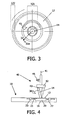
- FIG 3 a top view of the membrane 12 of the inventive device 10 is schematically shown.
- the actuation part 14 can be moved along a first inclination movement 31 to a predefined inclination.
- By moving the actuation part 14 in the rotational direction 45 along with a second inclination movement 31a another inclination position of the actuation part 14 can be reached (by maintaining the same degree of inclination of the membrane 12 but in another direction).
- By moving the actuation part 14 along a circle concentric with the membrane it is thereby possible to impart a continuous mixing movement on the fluid in the mixing chamber 20 thereby efficiently mixing the fluid or medium.
- the center region 121 and the edge region 122 of the membrane 12 are also shown.
- an apparatus 40 according to the present invention is shown schematically together with the device 10.
- the apparatus 40 comprises a motor means (not shown), especially an electric motor, able to rotate an eccentric 42 about an axis of rotation 41 and according to a rotational direction 45.
- An adapter part 43 is able to interface with the actuation part 14 of the device 10, especially by means of a ball bearing.
- the advantage of a ball bearing is that there is no mechanical wear in the system and the lifetime will be long.
- electrostatic plates can be used to induce an electrical force on a charge or an iron, or other magnetic material in the actuation part 14 can be actuated by switchable magnets around it, or a piezoelectric actuation is also possible according to the present invention.
- the amplitude of the eccentricity can be changed, i.e. the inclination 30 of the actuation part 14 can be changed by changing the eccentricity of the eccentric 42 of the apparatus 40.
- the amplitude of the eccentricity is limited by the elasticity of the membrane, which, in the context of the present invention, is also called flexible ceiling. A larger amplitude can be achieved by a larger diameter of the mixing chamber 20 and by a thinner membrane 20.
- the speed of rotation about the axis of rotation 41 is preferably in the range of approximately 1 to 100 rotations per second, especially preferred in the range of approximately 10 to 70 rotations per second, still more preferred in the range of approximately 20 to 50 rotations per second and most preferred in the range of approximately 34 to 45 rotations per second.
- the eccentric 42 imposes an inclination 30 on the actuation part 14 of the device.
- the liquid inside the mixing chamber 20 of the device 10 is mixed
- three different positions of the actuation part 14 are indicated (one in solid lines and the others in dashed lines).
Landscapes
- Chemical & Material Sciences (AREA)
- Chemical Kinetics & Catalysis (AREA)
- Separation Using Semi-Permeable Membranes (AREA)
- Accessories For Mixers (AREA)
- Apparatus Associated With Microorganisms And Enzymes (AREA)
- Treatment Of Fiber Materials (AREA)
Claims (10)
- Vorrichtung (10) zum Mischen eines flüssigen Mediums, wobei die Vorrichtung (10) eine flexible Membran (12) und ein Strukturteil (16) und ferner ein Betätigungsteil (14) umfasst, das sich auf einer ersten Seite der Membran (12) befindet, wobei die Vorrichtung ferner eine Mischkammer (20) umfasst, die sich auf einer zweiten Seite der Membran (12) befindet, wobei zumindest eine teilweise Neigung der Membran (12) als Folge einer Neigung (30) des Betätigungsteils (14) in Bezug auf das Strukturteil (16) eintritt,
dadurch gekennzeichnet, dass die Membran (12) und das Betätigungsteil (14) als eine einteilige Komponente ausgelegt sind. - Vorrichtung (10) nach Anspruch 1, wobei die Membran (12) und das Strukturteil (16) in einem Randbereich (122) der Membran (12) verbunden sind.
- Vorrichtung (10) nach Anspruch 1, wobei das Betätigungsteil (14) im Mittelteil (121) der Membran (12) vorgesehen ist.
- Vorrichtung (10) nach Anspruch 1, wobei die Vorrichtung (10) eine Folie (18) umfasst, die mit dem Strukturteil (16) verbunden ist, wobei sich die Folie (18) auf der zweiten Seite der Membran (12) befindet und wobei sich die Mischkammer (20) zwischen der Folie (18) und der Membran (12) befindet.
- Vorrichtung (10) nach Anspruch 4, wobei die Folie (18) eine flexible Folie ist.
- Gerät (40) zum Mischen eines flüssigen Mediums, das in einer Mischkammer (20) vorliegt, wobei das Gerät (40) eine Vorrichtung nach Anspruch 1 und Betätigungsmittel (42, 43) umfasst, die ein Betätigungsteil (14) der genannten Vorrichtung (10) veranlassen, eine Neigungsbewegung (31) auszuführen.
- Gerät (40) nach Anspruch 6, wobei das Gerät (40) ein Adapterteil (43) umfasst, das das Betätigungsteil (14) veranlassen kann, die Neigungsbewegung (31) auszuführen.
- Gerät (40) nach Anspruch 7, wobei das Adapterteil (43) als Kugellager ausgerührt ist.
- Gerät (40) nach Anspruch 8, wobei die Betätigungsmittel (42, 43) als Exzenter ausgeführt sind und das Adapterteil (43) eine Drehbewegung beschreibt.
- Gerät (40) nach Anspruch 9, wobei die Exzentrizität der Betätigungsmittel (42, 43) veränderbar ist.
Priority Applications (1)
| Application Number | Priority Date | Filing Date | Title |
|---|---|---|---|
| EP06765779A EP1896164B1 (de) | 2005-06-23 | 2006-06-19 | Vorrichtung zur mischung eines flüssigmediums |
Applications Claiming Priority (3)
| Application Number | Priority Date | Filing Date | Title |
|---|---|---|---|
| EP05105601 | 2005-06-23 | ||
| PCT/IB2006/051958 WO2006136999A1 (en) | 2005-06-23 | 2006-06-19 | Device for mixing a liquid medium |
| EP06765779A EP1896164B1 (de) | 2005-06-23 | 2006-06-19 | Vorrichtung zur mischung eines flüssigmediums |
Publications (2)
| Publication Number | Publication Date |
|---|---|
| EP1896164A1 EP1896164A1 (de) | 2008-03-12 |
| EP1896164B1 true EP1896164B1 (de) | 2012-02-08 |
Family
ID=37149341
Family Applications (1)
| Application Number | Title | Priority Date | Filing Date |
|---|---|---|---|
| EP06765779A Not-in-force EP1896164B1 (de) | 2005-06-23 | 2006-06-19 | Vorrichtung zur mischung eines flüssigmediums |
Country Status (7)
| Country | Link |
|---|---|
| US (1) | US8262281B2 (de) |
| EP (1) | EP1896164B1 (de) |
| JP (1) | JP2008543324A (de) |
| CN (1) | CN101203296A (de) |
| AT (1) | ATE544509T1 (de) |
| BR (1) | BRPI0612577A2 (de) |
| WO (1) | WO2006136999A1 (de) |
Families Citing this family (10)
| Publication number | Priority date | Publication date | Assignee | Title |
|---|---|---|---|---|
| US8262281B2 (en) * | 2005-06-23 | 2012-09-11 | Koninklijke Philips Electronics N.V. | Device for mixing a liquid medium |
| EP2421636B1 (de) | 2009-04-23 | 2012-10-03 | Koninklijke Philips Electronics N.V. | Mischer mit null totvolumen und mischverfahren |
| WO2012011090A1 (en) * | 2010-07-19 | 2012-01-26 | Analytical Developments Limited | Liquid analyzer device and related method |
| FR2969506B1 (fr) * | 2010-12-22 | 2013-02-15 | Sartorius Stedim Biotech Sa | Melange du contenu d'un conteneur flexible a usage biopharmaceutique. |
| CN104641240B (zh) * | 2012-09-24 | 2018-01-02 | 惠普发展公司,有限责任合伙企业 | 微流体混合装置 |
| FR3016811A1 (fr) * | 2014-01-24 | 2015-07-31 | Saint Gobain Performance Plast | Recipient-melangeur |
| CN112940061B (zh) | 2019-12-10 | 2024-05-03 | 财团法人工业技术研究院 | 核酸萃取装置 |
| TWI742905B (zh) * | 2019-12-10 | 2021-10-11 | 財團法人工業技術研究院 | 核酸萃取裝置 |
| CN115069130B (zh) * | 2022-06-27 | 2023-09-29 | 大连睦霖网络科技有限公司 | 一种海参肽制备口服液用原料混合装置 |
| GB2625087A (en) * | 2022-12-05 | 2024-06-12 | Stratec Se | Device and method for mixing of a fluid inside a container |
Family Cites Families (29)
| Publication number | Priority date | Publication date | Assignee | Title |
|---|---|---|---|---|
| US3097366A (en) * | 1963-07-16 | Winchell | ||
| US2152455A (en) * | 1938-10-28 | 1939-03-28 | George K Ballentine | Dishwashing machine |
| US2265516A (en) * | 1939-02-18 | 1941-12-09 | American Machine & Metals | Washing machine |
| US3132848A (en) * | 1961-05-22 | 1964-05-12 | Garlinghouse Brothers | Quick mixer |
| US3313240A (en) * | 1965-01-08 | 1967-04-11 | Itzhak E Bentov | Pump |
| US3744277A (en) * | 1970-12-16 | 1973-07-10 | P Grantham | Continuous laundering |
| US3765127A (en) * | 1971-12-20 | 1973-10-16 | Garlinghouse Brothers | Polisher and burnisher |
| US3947156A (en) * | 1972-03-08 | 1976-03-30 | Erich Becker | Diaphragm pump, particularly for the generation of vacuum |
| US3833203A (en) * | 1973-03-09 | 1974-09-03 | Garlinghouse Brothers Mfg Inc | Flexible mixer discharge |
| US3962892A (en) * | 1973-05-29 | 1976-06-15 | Garlinghouse Leslie H | Machine for controlled conditioning of liquids and mixtures |
| US4095288A (en) * | 1975-05-07 | 1978-06-13 | Garlinghouse Leslie H | Variable agitator mixer |
| GB1593122A (en) | 1977-03-03 | 1981-07-15 | Garlinghouse Brothers | Variable agitator mixer |
| JPS6265724A (ja) * | 1985-09-17 | 1987-03-25 | Chiyoda Tech & Ind Co Ltd | 袋詰め混練方法 |
| US5006104A (en) * | 1988-11-07 | 1991-04-09 | The Cleveland Clinic Foundation | Heart pump having contractible guide mechanism for pusher plate |
| US5193977A (en) * | 1991-11-22 | 1993-03-16 | Don Dame | Flexible membrane sealless centrifugal pump |
| JP3494447B2 (ja) * | 1992-07-31 | 2004-02-09 | Nok株式会社 | 混合方法および混合装置 |
| JP2000265945A (ja) * | 1998-11-10 | 2000-09-26 | Uct Kk | 薬液供給ポンプ、薬液供給装置、薬液供給システム、基板洗浄装置、薬液供給方法、及び基板洗浄方法 |
| GB9905312D0 (en) * | 1999-03-09 | 1999-04-28 | Rodgers Christopher R | Mixing method and apparatus |
| EP1161294B1 (de) | 1999-03-16 | 2002-07-24 | Fraunhofer-Gesellschaft Zur Förderung Der Angewandten Forschung E.V. | Aktiver mikromischer |
| FR2803225B1 (fr) | 1999-12-29 | 2002-06-14 | Biomerieux Sa | Appareil d'analyse a compartiment reactionnel a geometrie variable, procede de mixage et de guidage de liquides |
| ATE510614T1 (de) * | 2001-02-06 | 2011-06-15 | Levtech Inc | Vorrichtung und verfahren zum mischen von materialien, die unter sterilen bedingungen in einem behälter eingeschlossen sind |
| KR100916074B1 (ko) | 2001-03-09 | 2009-09-08 | 바이오마이크로 시스템즈, 인크. | 어레이에 대한 마이크로유체 인터페이스 방법 및인터페이스용 시스템 |
| WO2003015923A1 (en) | 2001-08-20 | 2003-02-27 | Biomicro Systems, Inc. | Fluid mixing in low aspect ratio chambers |
| US6634783B2 (en) * | 2001-08-09 | 2003-10-21 | Vitality Beverages, Inc. | Apparatus for agitating a fluid suspension |
| US6939032B2 (en) * | 2001-10-25 | 2005-09-06 | Erie Scientific Company | Cover slip mixing apparatus |
| EP1565257B1 (de) * | 2002-11-20 | 2007-01-10 | Unilever N.V. | Vorrichtung und verfahren zum mischen von komponenten |
| US7249880B2 (en) * | 2003-10-14 | 2007-07-31 | Advanced Technology Materials, Inc. | Flexible mixing bag for mixing solids, liquids and gases |
| JP2007527796A (ja) * | 2004-03-08 | 2007-10-04 | セワード リミテッド | 材料混合器及びこのような材料混合器に用いられるバッグ |
| US8262281B2 (en) * | 2005-06-23 | 2012-09-11 | Koninklijke Philips Electronics N.V. | Device for mixing a liquid medium |
-
2006
- 2006-06-19 US US11/917,953 patent/US8262281B2/en not_active Expired - Fee Related
- 2006-06-19 WO PCT/IB2006/051958 patent/WO2006136999A1/en not_active Ceased
- 2006-06-19 AT AT06765779T patent/ATE544509T1/de active
- 2006-06-19 JP JP2008517661A patent/JP2008543324A/ja active Pending
- 2006-06-19 CN CNA2006800222852A patent/CN101203296A/zh active Pending
- 2006-06-19 BR BRPI0612577A patent/BRPI0612577A2/pt not_active IP Right Cessation
- 2006-06-19 EP EP06765779A patent/EP1896164B1/de not_active Not-in-force
Also Published As
| Publication number | Publication date |
|---|---|
| ATE544509T1 (de) | 2012-02-15 |
| EP1896164A1 (de) | 2008-03-12 |
| BRPI0612577A2 (pt) | 2016-11-29 |
| WO2006136999A1 (en) | 2006-12-28 |
| CN101203296A (zh) | 2008-06-18 |
| JP2008543324A (ja) | 2008-12-04 |
| US8262281B2 (en) | 2012-09-11 |
| US20100039887A1 (en) | 2010-02-18 |
Similar Documents
| Publication | Publication Date | Title |
|---|---|---|
| Madou et al. | Lab on a CD | |
| US6326211B1 (en) | Method of manipulating a gas bubble in a microfluidic device | |
| US9086371B2 (en) | Fluidics devices | |
| US6168948B1 (en) | Miniaturized genetic analysis systems and methods | |
| US7611840B2 (en) | Method and device for the treatment of biological samples | |
| Madou et al. | LabCD: a centrifuge-based microfluidic platform for diagnostics | |
| EP2490812B1 (de) | Mikrofluidische kassette mit paralleler pneumatischer schnittstellenplatte | |
| EP0865606B1 (de) | Vorrichtung und verfahren zum bewegen von fluiden mittels zentrifugalbeschleunigung bei der automatischen laborbehandlung | |
| US8771609B2 (en) | Module for processing a biological sample, biochip kit, and use of the module | |
| US20060246490A1 (en) | Miniaturized genetic analysis systems and methods | |
| US20030175947A1 (en) | Enhanced mixing in microfluidic devices | |
| US20200156065A1 (en) | Processing Cartridge and Method for Detecting a Pathogen in a Sample | |
| US8262281B2 (en) | Device for mixing a liquid medium | |
| JP2005037368A (ja) | 化学反応用カートリッジおよびその作製方法および化学反応用カートリッジ駆動システム | |
| JP2007501405A (ja) | 一以上の試料の分析から物質又は検体を検出するための方法及び装置 | |
| US20050100946A1 (en) | Integrated nucleic acid diagnostic device and method for in-situ confocal microscopy | |
| CN101301632A (zh) | 化学反应盒、其制造方法和化学反应盒驱动系统 | |
| EP3793716A1 (de) | Systeme und verfahren zur nukleinsäurereinigung unter verwendung von durchflusszellen mit betätigten oberflächenmontierten strukturen | |
| US20070207063A1 (en) | Device for controlling fluid sequence | |
| Sin et al. | Integrated microfluidic systems for molecular diagnostics: a universal electrode platform for rapid diagnosis of urinary tract infections | |
| Thalhammer et al. | Integrated Lab-on-a-Chip System in Life Sciences | |
| Grodzinski et al. | The Use of Microfluidic Techniques in Microarray Applications | |
| Solomon | Microfluidic control in a biochip for DNA analysis |
Legal Events
| Date | Code | Title | Description |
|---|---|---|---|
| PUAI | Public reference made under article 153(3) epc to a published international application that has entered the european phase |
Free format text: ORIGINAL CODE: 0009012 |
|
| 17P | Request for examination filed |
Effective date: 20080123 |
|
| AK | Designated contracting states |
Kind code of ref document: A1 Designated state(s): AT BE BG CH CY CZ DE DK EE ES FI FR GB GR HU IE IS IT LI LT LU LV MC NL PL PT RO SE SI SK TR |
|
| DAX | Request for extension of the european patent (deleted) | ||
| DAX | Request for extension of the european patent (deleted) | ||
| R17P | Request for examination filed (corrected) |
Effective date: 20080123 |
|
| 17Q | First examination report despatched |
Effective date: 20100422 |
|
| GRAP | Despatch of communication of intention to grant a patent |
Free format text: ORIGINAL CODE: EPIDOSNIGR1 |
|
| GRAS | Grant fee paid |
Free format text: ORIGINAL CODE: EPIDOSNIGR3 |
|
| GRAA | (expected) grant |
Free format text: ORIGINAL CODE: 0009210 |
|
| AK | Designated contracting states |
Kind code of ref document: B1 Designated state(s): AT BE BG CH CY CZ DE DK EE ES FI FR GB GR HU IE IS IT LI LT LU LV MC NL PL PT RO SE SI SK TR |
|
| REG | Reference to a national code |
Ref country code: GB Ref legal event code: FG4D |
|
| REG | Reference to a national code |
Ref country code: CH Ref legal event code: EP Ref country code: AT Ref legal event code: REF Ref document number: 544509 Country of ref document: AT Kind code of ref document: T Effective date: 20120215 |
|
| REG | Reference to a national code |
Ref country code: DE Ref legal event code: R096 Ref document number: 602006027543 Country of ref document: DE Effective date: 20120405 |
|
| REG | Reference to a national code |
Ref country code: NL Ref legal event code: VDEP Effective date: 20120208 |
|
| LTIE | Lt: invalidation of european patent or patent extension |
Effective date: 20120208 |
|
| PG25 | Lapsed in a contracting state [announced via postgrant information from national office to epo] |
Ref country code: LT Free format text: LAPSE BECAUSE OF FAILURE TO SUBMIT A TRANSLATION OF THE DESCRIPTION OR TO PAY THE FEE WITHIN THE PRESCRIBED TIME-LIMIT Effective date: 20120208 Ref country code: NL Free format text: LAPSE BECAUSE OF FAILURE TO SUBMIT A TRANSLATION OF THE DESCRIPTION OR TO PAY THE FEE WITHIN THE PRESCRIBED TIME-LIMIT Effective date: 20120208 Ref country code: IS Free format text: LAPSE BECAUSE OF FAILURE TO SUBMIT A TRANSLATION OF THE DESCRIPTION OR TO PAY THE FEE WITHIN THE PRESCRIBED TIME-LIMIT Effective date: 20120608 |
|
| PG25 | Lapsed in a contracting state [announced via postgrant information from national office to epo] |
Ref country code: PL Free format text: LAPSE BECAUSE OF FAILURE TO SUBMIT A TRANSLATION OF THE DESCRIPTION OR TO PAY THE FEE WITHIN THE PRESCRIBED TIME-LIMIT Effective date: 20120208 Ref country code: PT Free format text: LAPSE BECAUSE OF FAILURE TO SUBMIT A TRANSLATION OF THE DESCRIPTION OR TO PAY THE FEE WITHIN THE PRESCRIBED TIME-LIMIT Effective date: 20120608 Ref country code: GR Free format text: LAPSE BECAUSE OF FAILURE TO SUBMIT A TRANSLATION OF THE DESCRIPTION OR TO PAY THE FEE WITHIN THE PRESCRIBED TIME-LIMIT Effective date: 20120509 Ref country code: LV Free format text: LAPSE BECAUSE OF FAILURE TO SUBMIT A TRANSLATION OF THE DESCRIPTION OR TO PAY THE FEE WITHIN THE PRESCRIBED TIME-LIMIT Effective date: 20120208 Ref country code: BE Free format text: LAPSE BECAUSE OF FAILURE TO SUBMIT A TRANSLATION OF THE DESCRIPTION OR TO PAY THE FEE WITHIN THE PRESCRIBED TIME-LIMIT Effective date: 20120208 Ref country code: FI Free format text: LAPSE BECAUSE OF FAILURE TO SUBMIT A TRANSLATION OF THE DESCRIPTION OR TO PAY THE FEE WITHIN THE PRESCRIBED TIME-LIMIT Effective date: 20120208 |
|
| PGFP | Annual fee paid to national office [announced via postgrant information from national office to epo] |
Ref country code: GB Payment date: 20120629 Year of fee payment: 7 |
|
| REG | Reference to a national code |
Ref country code: AT Ref legal event code: MK05 Ref document number: 544509 Country of ref document: AT Kind code of ref document: T Effective date: 20120208 |
|
| PG25 | Lapsed in a contracting state [announced via postgrant information from national office to epo] |
Ref country code: CY Free format text: LAPSE BECAUSE OF FAILURE TO SUBMIT A TRANSLATION OF THE DESCRIPTION OR TO PAY THE FEE WITHIN THE PRESCRIBED TIME-LIMIT Effective date: 20120208 |
|
| PG25 | Lapsed in a contracting state [announced via postgrant information from national office to epo] |
Ref country code: SI Free format text: LAPSE BECAUSE OF FAILURE TO SUBMIT A TRANSLATION OF THE DESCRIPTION OR TO PAY THE FEE WITHIN THE PRESCRIBED TIME-LIMIT Effective date: 20120208 Ref country code: EE Free format text: LAPSE BECAUSE OF FAILURE TO SUBMIT A TRANSLATION OF THE DESCRIPTION OR TO PAY THE FEE WITHIN THE PRESCRIBED TIME-LIMIT Effective date: 20120208 Ref country code: RO Free format text: LAPSE BECAUSE OF FAILURE TO SUBMIT A TRANSLATION OF THE DESCRIPTION OR TO PAY THE FEE WITHIN THE PRESCRIBED TIME-LIMIT Effective date: 20120208 Ref country code: SE Free format text: LAPSE BECAUSE OF FAILURE TO SUBMIT A TRANSLATION OF THE DESCRIPTION OR TO PAY THE FEE WITHIN THE PRESCRIBED TIME-LIMIT Effective date: 20120208 Ref country code: DK Free format text: LAPSE BECAUSE OF FAILURE TO SUBMIT A TRANSLATION OF THE DESCRIPTION OR TO PAY THE FEE WITHIN THE PRESCRIBED TIME-LIMIT Effective date: 20120208 Ref country code: CZ Free format text: LAPSE BECAUSE OF FAILURE TO SUBMIT A TRANSLATION OF THE DESCRIPTION OR TO PAY THE FEE WITHIN THE PRESCRIBED TIME-LIMIT Effective date: 20120208 |
|
| PG25 | Lapsed in a contracting state [announced via postgrant information from national office to epo] |
Ref country code: IT Free format text: LAPSE BECAUSE OF FAILURE TO SUBMIT A TRANSLATION OF THE DESCRIPTION OR TO PAY THE FEE WITHIN THE PRESCRIBED TIME-LIMIT Effective date: 20120208 Ref country code: SK Free format text: LAPSE BECAUSE OF FAILURE TO SUBMIT A TRANSLATION OF THE DESCRIPTION OR TO PAY THE FEE WITHIN THE PRESCRIBED TIME-LIMIT Effective date: 20120208 |
|
| PLBE | No opposition filed within time limit |
Free format text: ORIGINAL CODE: 0009261 |
|
| STAA | Information on the status of an ep patent application or granted ep patent |
Free format text: STATUS: NO OPPOSITION FILED WITHIN TIME LIMIT |
|
| PGFP | Annual fee paid to national office [announced via postgrant information from national office to epo] |
Ref country code: FR Payment date: 20120717 Year of fee payment: 7 Ref country code: DE Payment date: 20120830 Year of fee payment: 7 |
|
| 26N | No opposition filed |
Effective date: 20121109 |
|
| PG25 | Lapsed in a contracting state [announced via postgrant information from national office to epo] |
Ref country code: AT Free format text: LAPSE BECAUSE OF FAILURE TO SUBMIT A TRANSLATION OF THE DESCRIPTION OR TO PAY THE FEE WITHIN THE PRESCRIBED TIME-LIMIT Effective date: 20120208 Ref country code: MC Free format text: LAPSE BECAUSE OF NON-PAYMENT OF DUE FEES Effective date: 20120630 |
|
| REG | Reference to a national code |
Ref country code: CH Ref legal event code: PL |
|
| REG | Reference to a national code |
Ref country code: CH Ref legal event code: PL |
|
| REG | Reference to a national code |
Ref country code: DE Ref legal event code: R097 Ref document number: 602006027543 Country of ref document: DE Effective date: 20121109 |
|
| REG | Reference to a national code |
Ref country code: IE Ref legal event code: MM4A |
|
| PG25 | Lapsed in a contracting state [announced via postgrant information from national office to epo] |
Ref country code: IE Free format text: LAPSE BECAUSE OF NON-PAYMENT OF DUE FEES Effective date: 20120619 Ref country code: CH Free format text: LAPSE BECAUSE OF NON-PAYMENT OF DUE FEES Effective date: 20120630 Ref country code: ES Free format text: LAPSE BECAUSE OF FAILURE TO SUBMIT A TRANSLATION OF THE DESCRIPTION OR TO PAY THE FEE WITHIN THE PRESCRIBED TIME-LIMIT Effective date: 20120519 Ref country code: LI Free format text: LAPSE BECAUSE OF NON-PAYMENT OF DUE FEES Effective date: 20120630 |
|
| PG25 | Lapsed in a contracting state [announced via postgrant information from national office to epo] |
Ref country code: BG Free format text: LAPSE BECAUSE OF FAILURE TO SUBMIT A TRANSLATION OF THE DESCRIPTION OR TO PAY THE FEE WITHIN THE PRESCRIBED TIME-LIMIT Effective date: 20120508 |
|
| GBPC | Gb: european patent ceased through non-payment of renewal fee |
Effective date: 20130619 |
|
| REG | Reference to a national code |
Ref country code: DE Ref legal event code: R119 Ref document number: 602006027543 Country of ref document: DE Effective date: 20140101 |
|
| REG | Reference to a national code |
Ref country code: FR Ref legal event code: ST Effective date: 20140228 |
|
| PG25 | Lapsed in a contracting state [announced via postgrant information from national office to epo] |
Ref country code: DE Free format text: LAPSE BECAUSE OF NON-PAYMENT OF DUE FEES Effective date: 20140101 Ref country code: TR Free format text: LAPSE BECAUSE OF FAILURE TO SUBMIT A TRANSLATION OF THE DESCRIPTION OR TO PAY THE FEE WITHIN THE PRESCRIBED TIME-LIMIT Effective date: 20120208 Ref country code: GB Free format text: LAPSE BECAUSE OF NON-PAYMENT OF DUE FEES Effective date: 20130619 |
|
| PG25 | Lapsed in a contracting state [announced via postgrant information from national office to epo] |
Ref country code: FR Free format text: LAPSE BECAUSE OF NON-PAYMENT OF DUE FEES Effective date: 20130701 Ref country code: LU Free format text: LAPSE BECAUSE OF NON-PAYMENT OF DUE FEES Effective date: 20120619 |
|
| PG25 | Lapsed in a contracting state [announced via postgrant information from national office to epo] |
Ref country code: HU Free format text: LAPSE BECAUSE OF FAILURE TO SUBMIT A TRANSLATION OF THE DESCRIPTION OR TO PAY THE FEE WITHIN THE PRESCRIBED TIME-LIMIT Effective date: 20060619 |