EP1896675B1 - Armature adhesive dotee d'une protection coupe-feu et son procede de production - Google Patents
Armature adhesive dotee d'une protection coupe-feu et son procede de production Download PDFInfo
- Publication number
- EP1896675B1 EP1896675B1 EP06754187A EP06754187A EP1896675B1 EP 1896675 B1 EP1896675 B1 EP 1896675B1 EP 06754187 A EP06754187 A EP 06754187A EP 06754187 A EP06754187 A EP 06754187A EP 1896675 B1 EP1896675 B1 EP 1896675B1
- Authority
- EP
- European Patent Office
- Prior art keywords
- plate
- armouring
- protective layer
- adhesive
- layer
- Prior art date
- Legal status (The legal status is an assumption and is not a legal conclusion. Google has not performed a legal analysis and makes no representation as to the accuracy of the status listed.)
- Not-in-force
Links
Images

Classifications
-
- E—FIXED CONSTRUCTIONS
- E04—BUILDING
- E04G—SCAFFOLDING; FORMS; SHUTTERING; BUILDING IMPLEMENTS OR AIDS, OR THEIR USE; HANDLING BUILDING MATERIALS ON THE SITE; REPAIRING, BREAKING-UP OR OTHER WORK ON EXISTING BUILDINGS
- E04G23/00—Working measures on existing buildings
- E04G23/02—Repairing, e.g. filling cracks; Restoring; Altering; Enlarging
- E04G23/0218—Increasing or restoring the load-bearing capacity of building construction elements
-
- E—FIXED CONSTRUCTIONS
- E04—BUILDING
- E04B—GENERAL BUILDING CONSTRUCTIONS; WALLS, e.g. PARTITIONS; ROOFS; FLOORS; CEILINGS; INSULATION OR OTHER PROTECTION OF BUILDINGS
- E04B1/00—Constructions in general; Structures which are not restricted either to walls, e.g. partitions, or floors or ceilings or roofs
- E04B1/62—Insulation or other protection; Elements or use of specified material therefor
- E04B1/92—Protection against other undesired influences or dangers
- E04B1/94—Protection against other undesired influences or dangers against fire
-
- E—FIXED CONSTRUCTIONS
- E04—BUILDING
- E04G—SCAFFOLDING; FORMS; SHUTTERING; BUILDING IMPLEMENTS OR AIDS, OR THEIR USE; HANDLING BUILDING MATERIALS ON THE SITE; REPAIRING, BREAKING-UP OR OTHER WORK ON EXISTING BUILDINGS
- E04G23/00—Working measures on existing buildings
- E04G23/02—Repairing, e.g. filling cracks; Restoring; Altering; Enlarging
- E04G23/0218—Increasing or restoring the load-bearing capacity of building construction elements
- E04G2023/0251—Increasing or restoring the load-bearing capacity of building construction elements by using fiber reinforced plastic elements
Definitions
- the invention relates to a reinforcement, for a blanket or a carrier, with a fire protection formed by a plate cladding, wherein a reinforcing adhesive reinforcement is arranged on the underside of the ceiling or the carrier and at least covered on the underside by a plate clothing, the plate clothing at least one below the Adhesive reinforcement arranged plate layer comprises, which is constructed from at least one plate, and a method for producing a corresponding protected reinforcement.
- the adhesives used in the known technical solutions of adhesive reinforcements have excellent strengths at normal room temperatures, but already from temperatures of about 45-50 ° C, the load capacity of the adhesive is very strong and the failure criterion is reached quickly.
- the normally used epoxy resin adhesive can be used at temperatures above about 50 ° C, in any case above 60 ° C, in its function.
- U1 Fire protection clothing which comprises insulation of insulation wool at least 10 mm thick and, beneath it, a covering of fire protection plaster of the fire class F120 with a thickness of more than 20 mm.
- the object of the invention is therefore to provide a reinforcement with a formed by a plate cladding fire protection a method for their preparation, the or at yet reasonable manufacturing effort, only a slight increase in temperature even with prolonged exposure to fire in the adhesive reinforcement and thus maintaining the carrying capacity the carrier or the ceiling guaranteed.
- a reinforcing adhesive reinforcement is arranged on the underside of the ceiling or the carrier and covered at least on the underside by a plate clothing, wherein the plate clothing is formed of material containing water of crystallization and at least one plate layer disposed below the adhesive reinforcement, which is composed of at least one plate, and further wherein between the adhesive reinforcement and the plate clothing or within the plate clothing to secure and maintain the carrying capacity of the bond of adhesive reinforcement and ceiling in case of fire, a diffusion-inhibiting or -blocking and / or reflective protective layer is arranged.
- the protective layer is formed from a sheet-like film or as a lamination or application of a film on at least one plate.
- a basic idea of the present invention was that, with a desired limitation of the temperature increase, excessive vapor diffusion poses a problem when using eg plates with water of crystallization.
- the diffusion of hot steam may cause an additional and rapid increase in the temperature at the bond beyond the allowable height.
- common materials do not sufficiently limit vapor diffusion and thus can not always prevent an increase in the temperature of the adhesive above the threshold temperature. This means that common design solutions without reducing vapor diffusion can not always provide fire safety and contain safety hazards.
- gypsum boards are often used, which offer excellent in terms of their small thickness fire protection. This is due to the fact that the dihydrate (CaSO 4 ⁇ 2H 2 O) of the gypsum core contains about 20% of water of crystallization, which evaporates on exposure to fire and thereby consumes energy by conversion. A diffusion of the hot steam in the direction of the adhesive reinforcement and a consequent additional temperature increase of the adhesive reinforcement is effectively prevented or at least reduced by the protective layer according to the invention.
- a reflection layer which may be formed together with the vapor diffusion-inhibiting layer or as a separate layer. When formed as a separate layer, both layers can lie directly against one another. However, it is also conceivable to provide the vapor diffusion-inhibiting protective layer and a reflective protective layer spatially separated. Also, in some applications it may be sufficient to provide only a vapor diffusion-inhibiting protective layer without special reflection property or only a reflective protective layer without vapor diffusion barrier.
- the cooling effect of the water of crystallization can be used optimally with the solution according to the invention and, on the other hand, the water vapor which is hot above 100 ° C. can not cause a direct increase in temperature in the area of adhesive reinforcement.
- a reduced transmission of heat can produce a protective layer which is also heat-reflecting.
- a protective layer which, while not vapor-blocking but reflective, may also provide for reduced total heat transfer and thus good fire protection for the adhesive reinforcement for non-water-containing panels.
- the lamination of a film on at least one plate allows an efficient attachment of the plate clothing, as for the attachment of the film no separate operation is required. It is advantageous if the film is laminated on all plates of a plate layer, as this results in an effective vapor barrier and / or heat reflection.
- the formation of the protective layer on the other hand has the advantage that the selection of the plates is not limited to the laminated plates.
- materials for the film metal, in particular aluminum, PVC or polyethylene have proven to be advantageous.
- vapor barrier and / or reflective protective layer proposed here directly on the plates or on a separate support.
- the protective layer is applied directly to the at least one plate, in particular by spraying, troweling or brushing. This allows a good fixation of the protective layer on the at least one plate.
- the protective layer is preferably arranged or formed above or on the upper side of the at least one panel layer, namely the panel layer associated with the adhesive reinforcement. This has the advantage that the protective layer is not exposed to such high temperatures, as it is located on the top or inside of the fire protection clothing. This reduces the risk that the protective layer will be damaged.
- the protective layer can also be designed with a slightly lower temperature resistance, which can result in a cost savings. If the protective layer is designed as a lamination of a film on at least one plate, the at least one plate of the plate layer or the uppermost plate layer is preferably rotated so that the laminated film is facing upwards.
- the attachment of the protective layer on the upper or uppermost plate layer is particularly advantageous since, in this embodiment, crystal water can not diffuse from the plate to the adhesive reinforcement.
- the protective layer is arranged so that direct contact between it and the adhesive reinforcement is avoided and a distance of preferably at least 1 mm to 2 mm remains. This results in an air cushion between the adhesive reinforcement and the protective layer, so that on the one hand further improves the thermal insulation and on the other hand, a thermal bridge is avoided.
- the plate clothing comprises at least two plate layers arranged one above the other, the protective layer being arranged between the plate layers, for example between the two lowest or between the two uppermost plate layers.
- the protective layer being arranged between the plate layers, for example between the two lowest or between the two uppermost plate layers.
- the laminated plates of a plate layer can be arranged with their lamination facing an adjacent plate layer.
- the above-described embodiment of providing the protective layer between the plate layers may be considered primarily for a protective layer in which the reflective function is in the foreground. Specifically, this may be the case in applications in which the plate clothing is made from plates without embedded crystal water.
- lateral cover elements are arranged so that even the side of the adhesive reinforcement is a good thermal insulation.
- the plate clothing to cover the adhesive reinforcement by lateral plates on both or all sides of the Klebebeehrung, in particular so that the plate clothing comprises the adhesive reinforcement completely or almost completely.
- the protective layer is on or through the plate clothing, wrapping the adhesive reinforcement, each edge led to the carrier or to the ceiling.
- This embodiment has the advantage that the reinforcement is air-tight and vapor-tight or at least largely closed air- and vapor-tight from the environment, resulting in a particularly good thermal insulation, but especially a particularly low vapor diffusion or a particularly good vapor barrier.
- the protective layer formed as a film is in one piece.
- one-piece design of the protective layer results in a particularly effective vapor barrier, since there are no shocks or gaps between the sections of the protective layer, which could make the vapor barrier partially permeable.
- the protective layer may also include multiple sections with intermediate joints or butt joints.
- the joints of the protective layer are protected by fire protection, in particular by providing bent parallel end portions of the adjacent portions of the protective layer and / or by providing a separate cover strip.
- the foils or the laminated panels are joined together and / or glued as far as possible to form a protective layer which is as closed as possible. Bonding is preferably carried out so that all shocks are completely or almost completely sealed. The bond improves the vapor-tightness of the fire protection clothing.
- further plate layers can be arranged depending on the thickness of the fire protection target.
- the butt joints with a cover strip preferably from about 50 mm wide diffusion-inhibiting adhesive tape, for example, aluminum adhesive tape, especially on the back of the plate, taped.
- Aluminum tape can be applied easily and quickly and also has good properties in terms of the desired heat reflection or the desired vapor-tightness.
- the protective layer is temperature resistant up to at least 100 ° C and / or has a high vapor diffusion resistance and / or is reflective, especially heat-reflecting.
- the heat reflection also reduces the heat transfer of the fire protection clothing and can therefore also increase the fire resistance of the adhesive reinforcement.
- the film is formed with a water vapor diffusion equivalent air layer thickness greater than 20 m, preferably greater than 100 m, more preferably greater than 1000 m.
- a high water vapor diffusion equivalent air layer thickness results in an effective barrier to steam.
- the film is preferably in the form of a multilayer film, for example of polyethylene-coated and aluminum-coated kraft paper or single-layer films, for example of metal, in particular aluminum, PVC or polyethylene (PE).
- Multilayer films or composite films can be laminated particularly well. Films of aluminum or polyethylene and aluminum coated kraft paper reflect some of the heat radiation. In addition, this type of film is vapor-tight or largely vapor-tight. The combination of kraft paper and aluminum in different thicknesses increases the mechanical stability of the film.
- the multilayer or composite film comprises a kraft paper layer, in particular with a basis weight of 50 g / g 2 , a polyethylene layer, in particular with a weight per unit area of 30 g / m 2 and a preferably 9 ⁇ m thick aluminum foil with a water vapor diffusion equivalent air layer thickness s d greater than 1000 m. It has been found that this composition in the multilayer or composite film has particularly good technological properties in terms of plate coating, mechanical stability and vapor diffusion.
- the underside of the lowermost plate layer has a smooth and / or scratch-resistant, in particular visibly executed or executable surface.
- no additional layer for example, no plaster layer or plate layer, is required, which reduces the installation times for the Klebebestehrung.
- the installation costs can also be reduced as a result, since no additional material is required for the cover layer. Since, in particular, the application of an additional layer of plaster is not absolutely necessary, the accumulation of dirt is also reduced.
- To attach the plate clothing all technically common mounting options are considered, in particular screwing, clamping, pegging, each with or without substructure.
- the panel clothing is made of calcium silicate panels, cementitious mineral panels, vermiculite-based panels, but preferably of water-containing material, e.g. Gypsum in the form of glass-fiber-reinforced, glass-fiber-nonwoven or paper-fiber-reinforced plasterboard or plasterboard or formed from a combination of these plates.
- the panel apparel or fire protective garment converts a fire resistance time of F90, the panel garment having a total thickness of max. 40 - 50 mm.
- a small total thickness of the plate clothing is of great importance, since an adhesive reinforcement often takes place in old buildings with a comparatively low ceiling height. Due to a low overall height of the adhesive reinforcement including the panel cladding, the required or desired ceiling height can be made possible while at the same time compliance with the fire protection requirements, or at least made easier.
- the object of protective layer and plate clothing is to keep the temperature increase as long as possible before the carrier or the ceiling.
- a low thermal conductivity is advantageous for the plate clothing.
- the ceiling or the support comprises a reinforced concrete surface, wherein a cavity is formed between clothing and reinforced concrete surface, the thickness of carbon fibers for technical reasons is preferably at least about 6 mm.
- At least one plate layer is already coated with a film prior to installation in the plate clothing, since this can reduce the installation effort and thus the installation costs.
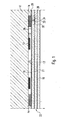
- FIG. 1 a ceiling 11 is shown with adhesive reinforcements 12 which causes Reinforcement Verhlebitch 13 on the ceiling 11 a reinforcement of this ceiling 11.
- the adhesive reinforcements 12 are covered with a full-surface, ie over the entire extent of the ceiling 11 extending plate clothing 22.
- the full-surface plate clothing 22 prevents from the side of a heating of the ceiling 11 takes place.
- the plate clothing 22 is constructed here from a total of three plate layers 15 to 17, namely a first plate layer 15 facing the adhesive reinforcement 12, a second plate layer 16 arranged underneath and a third plate layer 17 arranged below it.
- the plate layers 15, 16, 17 are directly adjacent to each other.
- the plate layers 15, 16, 17 consist of individual plates 21, preferably in some, more preferably in all plates 21 crystal water is stored, so that in case of fire, a cooling effect is achieved by the evaporation of the stored water of crystallization.
- the first, the adhesive reinforcement 12 facing plate layer 15 is provided with a laminated vapor-blocking protective layer 18 which is disposed on the adhesive reinforcements 12 facing the top of the plate layer 15.
- the sections 28, 29 of the protective layer 18 thus formed, that is to say the individual laminations on the respective plates 21, have end sections 33, 34 which in each case extend around the plate edges into the butt joints 26 between the plates 21.
- the end portions 33, 34 of adjacent plates 21 thus extend parallel to each other and are preferably adjacent to each other.
- the joints 26 may also be filled with special fillers, in particular adhesives, to effect an even more effective heat transfer barrier.
- the butt joints 26 may be covered on the underside with cover strips 30, preferably of self-adhesive, vapor diffusion-inhibiting foil strips, in order to effect a flat seal.
- a second and third plate layer 16, 17 or even further plates or plate layers can be provided under the first plate layer.
- the plate layers 15, 16, 17 are fixed to the ceiling 11 via plate strips 14 in the present embodiment.
- a protective layer 18 (coating material) for the gypsum plasterboard As a protective layer 18 (coating material) for the gypsum plasterboard, a multilayer film consisting of Kraft paper (50 g / m 2 ) and polyethylene (30 g / m 2 ) and 9 ⁇ m aluminum foil with a water vapor diffusion equivalent air layer thickness s d greater than 1000 m was used.
- a second and third plate layer 16 17 15 mm thick glass fiber non-wadded gypsum boards were stapled with steel staples on dowelled plate strip 14.
- the plate strips 14 themselves were formed from 6 mm thick glass fiber non-woven coated gypsum boards.
- the temperature increase in the area of the adhesive reinforcement 12 was about 8 K after 30 minutes, about 13 K after 60 minutes and about 21 K after 19 minutes, so that even with the small total thickness of 42, 5 mm gypsum boards a F90 protection function could be established.
- a temperature increase of approximately 49 K was measured, for example, after 90 minutes.
- FIG. 2 is a blanket 11 with adhesive reinforcements 12, which are fixed by reinforcing bonds 13 to the ceiling 11 and reinforce this, shown. Again, a full-surface panel clothing 22 is realized.
- two plate layers 15, 16 are arranged from plates 21 ', in which no crystal water is embedded in the plate structure. Between the plates 21 ', a reflective film with the reflective side in the direction away from the adhesive reinforcement 12 is arranged as a protective layer 18 and preferably attached only at points to the first plate layer 15 above it.
- Foils 35 are formed overlapping and preferably glued together. All plates 21 'of the two plate layers 15, 16 are attached via dowelled support profiles 20 made of thin-walled sheet steel to the ceiling 11.
- FIG. 3 is a further alternative embodiment of a reinforcement according to the invention illustrated.
- a ceiling 11 is equipped with adhesive reinforcement 12.
- the plate clothing is not full-surface, ie not the entire ceiling 11 designed to cover, but instead forms the plate clothing 22 here a strip-shaped channel surrounding the adhesive reinforcement 12.
- two plate layers 15, 16, preferably of plates 21, in which water of crystallization is embedded in the plate structure are provided below the adhesive reinforcements 12.
- the upper plate layer 15 is formed from plates 21, which are provided with a the adhesive reinforcements 12 facing, laminated steam-blocking protective layer 18.
- the plate layers 15, 16 are fastened to the plate 11 pegged plate stiffeners 14, wherein the plate strips 14 also made of non-combustible material, preferably of the same material as the first and second plate layer 15, 16 is formed.
- the adhesive reinforcements 12 facing sides of the doweled with the ceiling 11 panel strips 14 are taped with self-adhesive vapor-tight film strip 19 to create a vapor-tight surface seal the adhesive reinforcement 12 surrounding.
- the film strips 19 are expediently not only provided on the adhesive reinforcements 12 facing sides of the plate strip, but surround the adhesive reinforcement and the first plate layer 15 facing edge of the plate strip 14, so that the foil strip 19 at least partially the first plate layer 15 facing bottom of the Plate strip 14 covered.
- a bond 38 may be provided to further the vapor-tightness to improve.
- a second plate layer 16 or else further plate layers can be arranged below the first plate layer 15, depending on the required fire resistance. All plate layers can be attached directly or indirectly to the already mentioned dowelled plate strip 14.
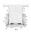
- FIG. 4 an embodiment of a reinforcement for a carrier 10 is shown.
- the carrier 10 is here equipped with two adhesive reinforcements 12, which are fastened by reinforcing bonds 13 on the carrier 10.
- the adhesive reinforcements 12 are protected by a channel-like carrier embracing plate clothing 22 from fire-induced heating.
- the plate clothing 22 is constructed as follows below the adhesive reinforcements 12, a first plate layer 15 and immediately below a second plate layer 16 is arranged. First and second plate layer 15, 16 are each end fixed to a lateral plate clothing 27.
- the provided on both sides of the carrier 10 lateral plate clothing 27 each comprises a first lateral plate layer 24 which faces the carrier 10, and a second lateral plate layer 25 which is on the first lateral plate layer 24 facing away from the carrier 10.
- the first lateral plate layer is bolted to the carrier 10, whereas the second lateral plate layer can be attached directly to the first lateral plate layer by screwing or stapling.
- the (lower) plate layers 15, 16 are fastened or screwed to the end faces of the lateral plate layers 24, 25 via steel clamps.
- the first (lower) plate layer 15 facing the adhesive reinforcements 12 and the two first (lateral) plate layers 24 facing the carrier 10 are each designed to face the carrier 10 with a protective layer 18 laminated on and vapor-blocking.
- the plates 21 proposed here forming plates 21 are preferably made of plates in which crystal water is incorporated in the plate structure, wherein the first lower plate layer 15 is formed of plates corresponding to the plates of the first lateral plate layer.
- the plates of the second (lower) plate layer 16 correspond to the plates of the second lateral plate layer 25.
- the film strips 19 can surround the edge of the first (lateral) plate layer 24 facing the lower plate layer 15 and the adhesive reinforcement 12 and at least partially cover the associated end face of the first lateral plate layer 24.
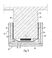
- FIG. 5 an embodiment for the reinforcement of a carrier 10 is shown, wherein the carrier 10 is equipped with a fortified by Rein Instituteverklebitch 13 adhesive reinforcement 12.
- a channel-like carrier-embracing plate clothing 22 is provided, wherein the plate clothing in principle of the attachment of the plate layers 15, 16 and the lateral plate layers 24, 25 her view analogous to the basis of FIG. 4 described embodiment is constructed.
- the protective layer 18 in the form of a vapor barrier film on the carrier base and adhesive reinforcement 12 hose-shaped and attached to flanges 36, 37 of the carrier 10 pointwise or surface.
- the protective layer 18 - at least over the cross section of the carrier 10 - be formed integrally continuous, so that transversely to the carrier 10, no film impact is required.
- the protective layer 18 is covered on the flanges 36, 37 of the carrier 10 by the first (lateral) plate layer 24, on each of which a second, lateral plate layer 25 is fastened. On the underside, the protective layer 18 is covered by a first plate layer 15 and a second plate layer 16.
- lower plate layers 15, 16 are attached to the end faces of the lateral plate layers 24, 25 by means of steel brackets.
- the lateral plate strips 24, 25 in the material preferably correspond to the lower plate layers 15, 16.
- the protective layer is to be chosen in particular from vapor-tight or vapor-tight and reflective coatings, these protective layers are then to be arranged as directly as possible as the closest layer under the adhesive reinforcements 12 and gluing joints in general.
- the protective layer is to be chosen in particular from reflective coatings, the protective layers can be arranged between the plates, a glued butt is not absolutely necessary and the reflective side of the protective layer of the preferably downwards (front) to align. Also needs in In this case, the protective layer does not necessarily protect the adhesive reinforcement laterally, as far as a radiation effect from the side is not to be expected.
Landscapes
- Engineering & Computer Science (AREA)
- Architecture (AREA)
- Civil Engineering (AREA)
- Chemical Kinetics & Catalysis (AREA)
- Electrochemistry (AREA)
- Mechanical Engineering (AREA)
- Chemical & Material Sciences (AREA)
- Structural Engineering (AREA)
- Building Environments (AREA)
- Laminated Bodies (AREA)
- Fireproofing Substances (AREA)
- Adhesives Or Adhesive Processes (AREA)
- Fire-Extinguishing Compositions (AREA)
- Aiming, Guidance, Guns With A Light Source, Armor, Camouflage, And Targets (AREA)
Claims (19)
- Armature, pour un plafond (11) ou un élément porteur (10), comportant un dispositif coupe-feu constitué par un placage (22),
une armature collée de renforcement (12) étant disposée en face inférieure sur le plafond (11) ou sur l'élément porteur (10) et étant recouverte au moins en face inférieure par le placage (22),
le placage (22) comportant au moins une couche de plaques (15, 16, 17) disposée sous l'armature collée (12) et composée d'au moins une plaque (21),
caractérisée en ce que- une couche de protection (18) limitant ou empêchant la diffusion et/ou réfléchissante est disposée entre l'armature collée (12) et le placage (22) ou à l'intérieur du placage (22) pour assurer et maintenir la portance de l'ensemble constitué par l'armature collée (12) et le plafond (11) ou l'élément porteur (10) en cas d'incendie,- le placage est composé d'un matériau contenant de l'eau de cristallisation et- la couche de protection est constituée par une feuille (18) de type bâche ou conçue comme contrecollage ou application d'une feuille sur au moins une plaque (21). - Armature selon la revendication 1,
caractérisée en ce que
la couche de protection (18) est apposée directement sur l'au moins une plaque (21), en particulier par projection, enduction à la spatule ou application à la brosse. - Armature selon la revendication 1 ou 2,
caractérisée en ce que
la couche de protection (18) est disposée au-dessus ou sur la face supérieure de l'au moins une couche de plaques (15, 16, 17), à savoir la couche de plaques (15) affectée à l'armature collée (12). - Armature selon l'une des revendications précédentes,
caractérisée en ce que
la couche de protection (18) est disposée de façon à éviter un contact direct entre elle et l'armature collée (12) et à laisser un espace de préférentiellement au moins 1 mm à 2 mm. - Armature selon l'une des revendications précédentes,
le placage (22) comportant au moins deux couches de plaques (15, 16, 17) superposées,
caractérisée en ce que
la couche de protection (18) est disposée entre deux couches de plaques (15, 16, 17), par exemple entre les deux couches de plaques inférieures ou supérieures (15, 16, 17). - Armature selon la revendication 5,
caractérisée en ce que
la couche de protection (18) est conçue comme couche de protection limitant la diffusion et prévue au-dessus de la dernière couche de plaques (15, 16, 17) avec de l'eau de cristallisation intercalée. - Armature selon l'une des revendications précédentes,
caractérisée en ce que
des éléments de recouvrement latéraux (27) sont disposés entre le placage (22) et le plafond pour envelopper l'armature collée (12). - Armature selon la revendication 7,
caractérisée en ce que
les éléments de recouvrement latéraux sont conçus comme placage (27) latéral également pourvu de la ou d'une autre couche de protection. - Armature selon l'une des revendications précédentes,
caractérisée en ce que
la couche de protection (18) longe ou traverse le placage (22, 27), enveloppant l'armature collée (12), jusqu'à l'élément porteur (10) ou jusqu'au plafond (11) du côté des bords. - Armature selon l'une des revendications précédentes,
caractérisée en ce que
la couche de protection (18) conçue comme feuille est constituée d'une seule pièce. - Armature selon l'une des revendications précédentes,
la couche de protection (18) comportant plusieurs sections (28, 29) présentant des jointures ou joints intermédiaires (26),
caractérisée en ce que
les joints (26) de la couche de protection (18) sont protégés par une protection anti-incendie, en particulier par prévision de sections terminales (33, 34) repliées et parallèles entre elles et/ou par prévision d'une bande de recouvrement (30). - Armature selon la revendication 11,
caractérisée en ce que
les joints (26) sont recouverts par la bande de recouvrement (30), constituée préférentiellement d'un ruban adhésif, par exemple un ruban adhésif en aluminium, limitant la diffusion, d'environ 50 mm de largeur. - Armature selon l'une des revendications précédentes,
caractérisée en ce que
la couche de protection (18) est thermorésistante jusqu'à au moins 100°C. - Armature selon l'une des revendications précédentes,
caractérisée en ce que
la couche de protection (18) est conçue avec une couche d'air à diffusion équivalente de vapeur d'eau, supérieure à 20 m, préférentiellement supérieure à 100 m, et plus préférentiellement supérieure à 1000 m. - Armature selon l'une des revendications précédentes,
caractérisée en ce que
la feuille (18) est conçue comme feuille multicouche, par exemple en papier kraft recouvert de polyéthylène ou d'aluminium, ou de feuilles monocouche, par exemple en aluminium, PVC ou polyéthylène. - Armature selon l'une des revendications précédentes,
caractérisée en ce que
la face inférieure de la couche de plaques inférieure (16, 17) présente une surface lisse et/ou anti-rayures, en particulier réalisée ou réalisable de manière apparente. - Armature selon l'une des revendications précédentes,
caractérisée en ce que
la suspension du placage (22) est effectuée moyennant des assemblages par vis ou par blocage ou par chevillage, respectivement avec ou sans structure de support. - Armature selon l'une des revendications précédentes,
caractérisée en ce que
le placage (22) est composé de plaques en silicate de calcium ou de plaques minérales liées par ciment ou de plaques à base de vermiculite, les plaques susmentionnées étant cependant composées d'un matériau contenant de l'eau de cristallisation, par exemple du plâtre, sous forme de plaques de plâtre ou de plaques de plâtre cartonnées armées de fibres de verre, enveloppées de toile de fibres de verre ou armées de fibres de papier, ou d'une combinaison de ces plaques. - Procédé de fabrication d'une armature, pour un plafond (11) ou un élément porteur (10), comportant un dispositif coupe-feu constitué par un placage (22),
où une armature collée de renforcement (12) est disposée en face inférieure sur le plafond (11) ou sur l'élément porteur (10) et étant recouverte au moins en face inférieure par un placage (22),
où au moins une couche de plaques (15, 16, 17) composée d'au moins une plaque (21) est disposée sous l'armature collée (12),
caractérisée en ce que
une couche de protection (18) limitant ou empêchant la diffusion et/ou réfléchissante est disposée lors de la pose du placage (22) entre l'armature collée (12) et le placage (22) ou à l'intérieur du placage (22) pour assurer et maintenir la
portance de l'ensemble constitué par l'armature collée (12) et le plafond (11) ou l'élément porteur (10) en cas d'incendie,
le placage étant composé d'un matériau contenant de l'eau de cristallisation et la couche de protection étant constituée par une feuille (18) de type bâche ou comme contrecollage ou application d'une feuille sur au moins une plaque (21).
Priority Applications (1)
| Application Number | Priority Date | Filing Date | Title |
|---|---|---|---|
| PL06754187T PL1896675T3 (pl) | 2005-06-16 | 2006-06-07 | Zbrojenie klejone z ochroną przeciwpożarową i sposób jego wytwarzania |
Applications Claiming Priority (2)
| Application Number | Priority Date | Filing Date | Title |
|---|---|---|---|
| DE102005028071A DE102005028071B3 (de) | 2005-06-16 | 2005-06-16 | Klebebewehrung mit Brandschutz |
| PCT/EP2006/005428 WO2006133836A1 (fr) | 2005-06-16 | 2006-06-07 | Armature adhesive dotee d'une protection coupe-feu et son procede de production |
Publications (3)
| Publication Number | Publication Date |
|---|---|
| EP1896675A1 EP1896675A1 (fr) | 2008-03-12 |
| EP1896675B1 true EP1896675B1 (fr) | 2010-02-10 |
| EP1896675B9 EP1896675B9 (fr) | 2010-06-02 |
Family
ID=36717087
Family Applications (1)
| Application Number | Title | Priority Date | Filing Date |
|---|---|---|---|
| EP06754187A Not-in-force EP1896675B9 (fr) | 2005-06-16 | 2006-06-07 | Armature adhesive dotee d'une protection coupe-feu et son procede de production |
Country Status (6)
| Country | Link |
|---|---|
| EP (1) | EP1896675B9 (fr) |
| AT (1) | ATE457394T1 (fr) |
| DE (2) | DE102005028071B3 (fr) |
| ES (1) | ES2341183T3 (fr) |
| PL (1) | PL1896675T3 (fr) |
| WO (1) | WO2006133836A1 (fr) |
Family Cites Families (5)
| Publication number | Priority date | Publication date | Assignee | Title |
|---|---|---|---|---|
| DE3004905A1 (de) | 1980-02-09 | 1981-08-20 | Wilser, Fried, 6900 Heidelberg | Verbundplatten, mehrflaechig, feuerfest, den waermedurchgang reduzierend |
| DE3333615A1 (de) * | 1983-09-17 | 1985-04-18 | System- Und Verfahrenstechnik Verwaltungsgesellschaft Mbh, 2105 Seevetal | Brandschutzplatte |
| US5404687A (en) * | 1991-04-24 | 1995-04-11 | Avco Corporation | Intumescent fireproofing panel system |
| US6074714A (en) * | 1997-05-23 | 2000-06-13 | No Fire Technologies, Inc. | Fire and heat protection wrap for structural steel columns, beams and open web joists |
| DE202004009680U1 (de) * | 2004-06-18 | 2004-09-16 | Schulze, Karl-Heinz | Bauteil mit Klebebewehrung und Brandschutzbekleidung |
-
2005
- 2005-06-16 DE DE102005028071A patent/DE102005028071B3/de not_active Expired - Fee Related
-
2006
- 2006-06-07 PL PL06754187T patent/PL1896675T3/pl unknown
- 2006-06-07 DE DE502006006114T patent/DE502006006114D1/de active Active
- 2006-06-07 AT AT06754187T patent/ATE457394T1/de active
- 2006-06-07 WO PCT/EP2006/005428 patent/WO2006133836A1/fr not_active Ceased
- 2006-06-07 EP EP06754187A patent/EP1896675B9/fr not_active Not-in-force
- 2006-06-07 ES ES06754187T patent/ES2341183T3/es active Active
Also Published As
| Publication number | Publication date |
|---|---|
| EP1896675B9 (fr) | 2010-06-02 |
| WO2006133836A1 (fr) | 2006-12-21 |
| DE502006006114D1 (de) | 2010-03-25 |
| ES2341183T3 (es) | 2010-06-16 |
| ATE457394T1 (de) | 2010-02-15 |
| DE102005028071B3 (de) | 2006-11-30 |
| PL1896675T3 (pl) | 2010-06-30 |
| EP1896675A1 (fr) | 2008-03-12 |
Similar Documents
| Publication | Publication Date | Title |
|---|---|---|
| EP2855793B1 (fr) | Élément de couverture de toiture | |
| DE4004103C2 (de) | Wandelement für Gebäudeaußenwände und Verfahren zur Herstellung eines Wandelements | |
| EP3060725B1 (fr) | Composite anti-effraction et structure de mur porteur, de toit ou de plafond | |
| EP2726680B1 (fr) | Construction de façade pour l'isolation thermique et l'habillage de parois de bâtiments, et procédé de fabrication d'une telle construction de façade | |
| EP0017969A2 (fr) | Couche extérieure incombustible d'isolation thermique avec revêtement de surface | |
| EP0682163B1 (fr) | Ensemble de pièces pour systèmes composites de parements d'isolation thermique et façades ventilées | |
| DE3409592A1 (de) | Waermedaemmsystem | |
| DE19704112C2 (de) | Wärmedämmende Fassadenverkleidung | |
| DE19860974C1 (de) | Wärme-und/oder Schalldämmelement | |
| EP1936056A2 (fr) | Composant plat | |
| DE102004028227A1 (de) | Anordnung zur Befestigung von Vakuumdämmplatten an Baukörpern | |
| EP1896675B1 (fr) | Armature adhesive dotee d'une protection coupe-feu et son procede de production | |
| EP2820197B1 (fr) | Élément d'isolation | |
| AT409279B (de) | Verbundplatte zum brandschutz | |
| EP1045945B1 (fr) | Utilisation d'elements support pour fixer des substructures | |
| DE2514259C2 (de) | Dachkonstruktion mit plattenförmigen Isolierstoffbauelementen sowie Abstandhalter für die Dachkonstruktion | |
| DE2700416A1 (de) | Verbundflaechentragwerk fuer daecher | |
| DE8500260U1 (de) | Dachelement mit hoher luftschalldaemmung | |
| DE19857383A1 (de) | Wärme- und/oder Schalldämmelement | |
| DE102012021898A1 (de) | Gebäude | |
| DE3021537A1 (de) | Isolierung fuer den hoch- und tiefbau | |
| EP3024992B1 (fr) | Système de fixation d'éléments isolants | |
| EP2733272B1 (fr) | Systèmes composites d'isolation thermique pour façades de bâtiment | |
| EP0936063A2 (fr) | Elément de construction composite thermo-isolant | |
| AT4133U1 (de) | Wärmedämm-fassade |
Legal Events
| Date | Code | Title | Description |
|---|---|---|---|
| PUAI | Public reference made under article 153(3) epc to a published international application that has entered the european phase |
Free format text: ORIGINAL CODE: 0009012 |
|
| 17P | Request for examination filed |
Effective date: 20080115 |
|
| AK | Designated contracting states |
Kind code of ref document: A1 Designated state(s): AT BE BG CH CY CZ DE DK EE ES FI FR GB GR HU IE IS IT LI LT LU LV MC NL PL PT RO SE SI SK TR |
|
| DAX | Request for extension of the european patent (deleted) | ||
| RIN1 | Information on inventor provided before grant (corrected) |
Inventor name: MUELLER, VOLKER Inventor name: SCHAPER, JENS Inventor name: KRAEMER, GEORG |
|
| DAX | Request for extension of the european patent (deleted) | ||
| GRAP | Despatch of communication of intention to grant a patent |
Free format text: ORIGINAL CODE: EPIDOSNIGR1 |
|
| GRAS | Grant fee paid |
Free format text: ORIGINAL CODE: EPIDOSNIGR3 |
|
| GRAA | (expected) grant |
Free format text: ORIGINAL CODE: 0009210 |
|
| AK | Designated contracting states |
Kind code of ref document: B1 Designated state(s): AT BE BG CH CY CZ DE DK EE ES FI FR GB GR HU IE IS IT LI LT LU LV MC NL PL PT RO SE SI SK TR |
|
| REG | Reference to a national code |
Ref country code: GB Ref legal event code: FG4D Free format text: NOT ENGLISH |
|
| REG | Reference to a national code |
Ref country code: CH Ref legal event code: EP |
|
| REG | Reference to a national code |
Ref country code: CH Ref legal event code: NV Representative=s name: CAVID GMBH |
|
| REG | Reference to a national code |
Ref country code: IE Ref legal event code: FG4D |
|
| REF | Corresponds to: |
Ref document number: 502006006114 Country of ref document: DE Date of ref document: 20100325 Kind code of ref document: P |
|
| REG | Reference to a national code |
Ref country code: ES Ref legal event code: FG2A Ref document number: 2341183 Country of ref document: ES Kind code of ref document: T3 |
|
| REG | Reference to a national code |
Ref country code: NL Ref legal event code: VDEP Effective date: 20100210 |
|
| LTIE | Lt: invalidation of european patent or patent extension |
Effective date: 20100210 |
|
| PG25 | Lapsed in a contracting state [announced via postgrant information from national office to epo] |
Ref country code: LT Free format text: LAPSE BECAUSE OF FAILURE TO SUBMIT A TRANSLATION OF THE DESCRIPTION OR TO PAY THE FEE WITHIN THE PRESCRIBED TIME-LIMIT Effective date: 20100210 Ref country code: IS Free format text: LAPSE BECAUSE OF FAILURE TO SUBMIT A TRANSLATION OF THE DESCRIPTION OR TO PAY THE FEE WITHIN THE PRESCRIBED TIME-LIMIT Effective date: 20100610 Ref country code: PT Free format text: LAPSE BECAUSE OF FAILURE TO SUBMIT A TRANSLATION OF THE DESCRIPTION OR TO PAY THE FEE WITHIN THE PRESCRIBED TIME-LIMIT Effective date: 20100611 |
|
| PG25 | Lapsed in a contracting state [announced via postgrant information from national office to epo] |
Ref country code: FI Free format text: LAPSE BECAUSE OF FAILURE TO SUBMIT A TRANSLATION OF THE DESCRIPTION OR TO PAY THE FEE WITHIN THE PRESCRIBED TIME-LIMIT Effective date: 20100210 Ref country code: SI Free format text: LAPSE BECAUSE OF FAILURE TO SUBMIT A TRANSLATION OF THE DESCRIPTION OR TO PAY THE FEE WITHIN THE PRESCRIBED TIME-LIMIT Effective date: 20100210 Ref country code: LV Free format text: LAPSE BECAUSE OF FAILURE TO SUBMIT A TRANSLATION OF THE DESCRIPTION OR TO PAY THE FEE WITHIN THE PRESCRIBED TIME-LIMIT Effective date: 20100210 |
|
| REG | Reference to a national code |
Ref country code: IE Ref legal event code: FD4D |
|
| PG25 | Lapsed in a contracting state [announced via postgrant information from national office to epo] |
Ref country code: NL Free format text: LAPSE BECAUSE OF FAILURE TO SUBMIT A TRANSLATION OF THE DESCRIPTION OR TO PAY THE FEE WITHIN THE PRESCRIBED TIME-LIMIT Effective date: 20100210 Ref country code: EE Free format text: LAPSE BECAUSE OF FAILURE TO SUBMIT A TRANSLATION OF THE DESCRIPTION OR TO PAY THE FEE WITHIN THE PRESCRIBED TIME-LIMIT Effective date: 20100210 Ref country code: CY Free format text: LAPSE BECAUSE OF FAILURE TO SUBMIT A TRANSLATION OF THE DESCRIPTION OR TO PAY THE FEE WITHIN THE PRESCRIBED TIME-LIMIT Effective date: 20100210 Ref country code: SE Free format text: LAPSE BECAUSE OF FAILURE TO SUBMIT A TRANSLATION OF THE DESCRIPTION OR TO PAY THE FEE WITHIN THE PRESCRIBED TIME-LIMIT Effective date: 20100210 Ref country code: RO Free format text: LAPSE BECAUSE OF FAILURE TO SUBMIT A TRANSLATION OF THE DESCRIPTION OR TO PAY THE FEE WITHIN THE PRESCRIBED TIME-LIMIT Effective date: 20100210 Ref country code: GR Free format text: LAPSE BECAUSE OF FAILURE TO SUBMIT A TRANSLATION OF THE DESCRIPTION OR TO PAY THE FEE WITHIN THE PRESCRIBED TIME-LIMIT Effective date: 20100511 Ref country code: IE Free format text: LAPSE BECAUSE OF FAILURE TO SUBMIT A TRANSLATION OF THE DESCRIPTION OR TO PAY THE FEE WITHIN THE PRESCRIBED TIME-LIMIT Effective date: 20100210 |
|
| PGFP | Annual fee paid to national office [announced via postgrant information from national office to epo] |
Ref country code: ES Payment date: 20100723 Year of fee payment: 5 |
|
| PG25 | Lapsed in a contracting state [announced via postgrant information from national office to epo] |
Ref country code: BG Free format text: LAPSE BECAUSE OF FAILURE TO SUBMIT A TRANSLATION OF THE DESCRIPTION OR TO PAY THE FEE WITHIN THE PRESCRIBED TIME-LIMIT Effective date: 20100510 Ref country code: CZ Free format text: LAPSE BECAUSE OF FAILURE TO SUBMIT A TRANSLATION OF THE DESCRIPTION OR TO PAY THE FEE WITHIN THE PRESCRIBED TIME-LIMIT Effective date: 20100210 Ref country code: SK Free format text: LAPSE BECAUSE OF FAILURE TO SUBMIT A TRANSLATION OF THE DESCRIPTION OR TO PAY THE FEE WITHIN THE PRESCRIBED TIME-LIMIT Effective date: 20100210 |
|
| PLBE | No opposition filed within time limit |
Free format text: ORIGINAL CODE: 0009261 |
|
| STAA | Information on the status of an ep patent application or granted ep patent |
Free format text: STATUS: NO OPPOSITION FILED WITHIN TIME LIMIT |
|
| 26N | No opposition filed |
Effective date: 20101111 |
|
| PG25 | Lapsed in a contracting state [announced via postgrant information from national office to epo] |
Ref country code: DK Free format text: LAPSE BECAUSE OF FAILURE TO SUBMIT A TRANSLATION OF THE DESCRIPTION OR TO PAY THE FEE WITHIN THE PRESCRIBED TIME-LIMIT Effective date: 20100210 Ref country code: MC Free format text: LAPSE BECAUSE OF NON-PAYMENT OF DUE FEES Effective date: 20100630 |
|
| REG | Reference to a national code |
Ref country code: CH Ref legal event code: NV Representative=s name: REUTELER & CIE SA |
|
| PG25 | Lapsed in a contracting state [announced via postgrant information from national office to epo] |
Ref country code: HU Free format text: LAPSE BECAUSE OF FAILURE TO SUBMIT A TRANSLATION OF THE DESCRIPTION OR TO PAY THE FEE WITHIN THE PRESCRIBED TIME-LIMIT Effective date: 20100811 Ref country code: LU Free format text: LAPSE BECAUSE OF NON-PAYMENT OF DUE FEES Effective date: 20100607 |
|
| PG25 | Lapsed in a contracting state [announced via postgrant information from national office to epo] |
Ref country code: TR Free format text: LAPSE BECAUSE OF FAILURE TO SUBMIT A TRANSLATION OF THE DESCRIPTION OR TO PAY THE FEE WITHIN THE PRESCRIBED TIME-LIMIT Effective date: 20100210 |
|
| PGFP | Annual fee paid to national office [announced via postgrant information from national office to epo] |
Ref country code: AT Payment date: 20120626 Year of fee payment: 7 |
|
| PGFP | Annual fee paid to national office [announced via postgrant information from national office to epo] |
Ref country code: CH Payment date: 20130628 Year of fee payment: 8 |
|
| REG | Reference to a national code |
Ref country code: ES Ref legal event code: FD2A Effective date: 20131029 |
|
| PG25 | Lapsed in a contracting state [announced via postgrant information from national office to epo] |
Ref country code: ES Free format text: LAPSE BECAUSE OF NON-PAYMENT OF DUE FEES Effective date: 20110608 |
|
| PGFP | Annual fee paid to national office [announced via postgrant information from national office to epo] |
Ref country code: BE Payment date: 20130731 Year of fee payment: 8 |
|
| PGFP | Annual fee paid to national office [announced via postgrant information from national office to epo] |
Ref country code: IT Payment date: 20130627 Year of fee payment: 8 |
|
| REG | Reference to a national code |
Ref country code: CH Ref legal event code: PL |
|
| REG | Reference to a national code |
Ref country code: AT Ref legal event code: MM01 Ref document number: 457394 Country of ref document: AT Kind code of ref document: T Effective date: 20140607 |
|
| PG25 | Lapsed in a contracting state [announced via postgrant information from national office to epo] |
Ref country code: LI Free format text: LAPSE BECAUSE OF NON-PAYMENT OF DUE FEES Effective date: 20140630 Ref country code: CH Free format text: LAPSE BECAUSE OF NON-PAYMENT OF DUE FEES Effective date: 20140630 Ref country code: IT Free format text: LAPSE BECAUSE OF NON-PAYMENT OF DUE FEES Effective date: 20140607 |
|
| PG25 | Lapsed in a contracting state [announced via postgrant information from national office to epo] |
Ref country code: AT Free format text: LAPSE BECAUSE OF NON-PAYMENT OF DUE FEES Effective date: 20140607 |
|
| PGFP | Annual fee paid to national office [announced via postgrant information from national office to epo] |
Ref country code: PL Payment date: 20150413 Year of fee payment: 10 |
|
| REG | Reference to a national code |
Ref country code: FR Ref legal event code: PLFP Year of fee payment: 11 |
|
| PGFP | Annual fee paid to national office [announced via postgrant information from national office to epo] |
Ref country code: FR Payment date: 20160630 Year of fee payment: 11 |
|
| PG25 | Lapsed in a contracting state [announced via postgrant information from national office to epo] |
Ref country code: BE Free format text: LAPSE BECAUSE OF NON-PAYMENT OF DUE FEES Effective date: 20140630 |
|
| PG25 | Lapsed in a contracting state [announced via postgrant information from national office to epo] |
Ref country code: PL Free format text: LAPSE BECAUSE OF NON-PAYMENT OF DUE FEES Effective date: 20160607 |
|
| REG | Reference to a national code |
Ref country code: FR Ref legal event code: ST Effective date: 20180228 |
|
| PG25 | Lapsed in a contracting state [announced via postgrant information from national office to epo] |
Ref country code: FR Free format text: LAPSE BECAUSE OF NON-PAYMENT OF DUE FEES Effective date: 20170630 |
|
| P01 | Opt-out of the competence of the unified patent court (upc) registered |
Effective date: 20230822 |
|
| PGFP | Annual fee paid to national office [announced via postgrant information from national office to epo] |
Ref country code: GB Payment date: 20240627 Year of fee payment: 19 |
|
| PGFP | Annual fee paid to national office [announced via postgrant information from national office to epo] |
Ref country code: DE Payment date: 20240627 Year of fee payment: 19 |
|
| REG | Reference to a national code |
Ref country code: DE Ref legal event code: R119 Ref document number: 502006006114 Country of ref document: DE |
|
| GBPC | Gb: european patent ceased through non-payment of renewal fee |
Effective date: 20250607 |
|
| PG25 | Lapsed in a contracting state [announced via postgrant information from national office to epo] |
Ref country code: GB Free format text: LAPSE BECAUSE OF NON-PAYMENT OF DUE FEES Effective date: 20250607 |
|
| PG25 | Lapsed in a contracting state [announced via postgrant information from national office to epo] |
Ref country code: DE Free format text: LAPSE BECAUSE OF NON-PAYMENT OF DUE FEES Effective date: 20260101 |