EP1896746B1 - Position de référence d'embrayage - Google Patents
Position de référence d'embrayage Download PDFInfo
- Publication number
- EP1896746B1 EP1896746B1 EP06753279A EP06753279A EP1896746B1 EP 1896746 B1 EP1896746 B1 EP 1896746B1 EP 06753279 A EP06753279 A EP 06753279A EP 06753279 A EP06753279 A EP 06753279A EP 1896746 B1 EP1896746 B1 EP 1896746B1
- Authority
- EP
- European Patent Office
- Prior art keywords
- clutch
- actuator
- time period
- reference position
- measurement
- Prior art date
- Legal status (The legal status is an assumption and is not a legal conclusion. Google has not performed a legal analysis and makes no representation as to the accuracy of the status listed.)
- Not-in-force
Links
- 238000000034 method Methods 0.000 claims abstract description 43
- 238000005259 measurement Methods 0.000 claims abstract description 26
- 230000009471 action Effects 0.000 claims description 8
- 230000008569 process Effects 0.000 abstract description 12
- 230000008878 coupling Effects 0.000 description 30
- 238000010168 coupling process Methods 0.000 description 30
- 238000005859 coupling reaction Methods 0.000 description 30
- 230000033001 locomotion Effects 0.000 description 7
- 238000012795 verification Methods 0.000 description 6
- 230000004913 activation Effects 0.000 description 4
- 238000006073 displacement reaction Methods 0.000 description 4
- 230000005540 biological transmission Effects 0.000 description 3
- 230000000694 effects Effects 0.000 description 3
- 230000008859 change Effects 0.000 description 2
- 238000001514 detection method Methods 0.000 description 2
- 238000011109 contamination Methods 0.000 description 1
- 230000001351 cycling effect Effects 0.000 description 1
- 238000005516 engineering process Methods 0.000 description 1
- 238000012806 monitoring device Methods 0.000 description 1
Images

Classifications
-
- F—MECHANICAL ENGINEERING; LIGHTING; HEATING; WEAPONS; BLASTING
- F16—ENGINEERING ELEMENTS AND UNITS; GENERAL MEASURES FOR PRODUCING AND MAINTAINING EFFECTIVE FUNCTIONING OF MACHINES OR INSTALLATIONS; THERMAL INSULATION IN GENERAL
- F16D—COUPLINGS FOR TRANSMITTING ROTATION; CLUTCHES; BRAKES
- F16D48/00—External control of clutches
- F16D48/06—Control by electric or electronic means, e.g. of fluid pressure
-
- F—MECHANICAL ENGINEERING; LIGHTING; HEATING; WEAPONS; BLASTING
- F16—ENGINEERING ELEMENTS AND UNITS; GENERAL MEASURES FOR PRODUCING AND MAINTAINING EFFECTIVE FUNCTIONING OF MACHINES OR INSTALLATIONS; THERMAL INSULATION IN GENERAL
- F16D—COUPLINGS FOR TRANSMITTING ROTATION; CLUTCHES; BRAKES
- F16D48/00—External control of clutches
- F16D48/06—Control by electric or electronic means, e.g. of fluid pressure
- F16D48/064—Control of electrically or electromagnetically actuated clutches
-
- B—PERFORMING OPERATIONS; TRANSPORTING
- B60—VEHICLES IN GENERAL
- B60W—CONJOINT CONTROL OF VEHICLE SUB-UNITS OF DIFFERENT TYPE OR DIFFERENT FUNCTION; CONTROL SYSTEMS SPECIALLY ADAPTED FOR HYBRID VEHICLES; ROAD VEHICLE DRIVE CONTROL SYSTEMS FOR PURPOSES NOT RELATED TO THE CONTROL OF A PARTICULAR SUB-UNIT
- B60W2510/00—Input parameters relating to a particular sub-units
- B60W2510/02—Clutches
- B60W2510/0208—Clutch engagement state, e.g. engaged or disengaged
- B60W2510/0225—Clutch actuator position
-
- F—MECHANICAL ENGINEERING; LIGHTING; HEATING; WEAPONS; BLASTING
- F16—ENGINEERING ELEMENTS AND UNITS; GENERAL MEASURES FOR PRODUCING AND MAINTAINING EFFECTIVE FUNCTIONING OF MACHINES OR INSTALLATIONS; THERMAL INSULATION IN GENERAL
- F16D—COUPLINGS FOR TRANSMITTING ROTATION; CLUTCHES; BRAKES
- F16D2300/00—Special features for couplings or clutches
- F16D2300/14—Clutches which are normally open, i.e. not engaged in released state
-
- F—MECHANICAL ENGINEERING; LIGHTING; HEATING; WEAPONS; BLASTING
- F16—ENGINEERING ELEMENTS AND UNITS; GENERAL MEASURES FOR PRODUCING AND MAINTAINING EFFECTIVE FUNCTIONING OF MACHINES OR INSTALLATIONS; THERMAL INSULATION IN GENERAL
- F16D—COUPLINGS FOR TRANSMITTING ROTATION; CLUTCHES; BRAKES
- F16D2500/00—External control of clutches by electric or electronic means
- F16D2500/30—Signal inputs
- F16D2500/302—Signal inputs from the actuator
- F16D2500/3026—Stroke
-
- F—MECHANICAL ENGINEERING; LIGHTING; HEATING; WEAPONS; BLASTING
- F16—ENGINEERING ELEMENTS AND UNITS; GENERAL MEASURES FOR PRODUCING AND MAINTAINING EFFECTIVE FUNCTIONING OF MACHINES OR INSTALLATIONS; THERMAL INSULATION IN GENERAL
- F16D—COUPLINGS FOR TRANSMITTING ROTATION; CLUTCHES; BRAKES
- F16D2500/00—External control of clutches by electric or electronic means
- F16D2500/30—Signal inputs
- F16D2500/304—Signal inputs from the clutch
- F16D2500/30401—On-off signal indicating the engage or disengaged position of the clutch
-
- F—MECHANICAL ENGINEERING; LIGHTING; HEATING; WEAPONS; BLASTING
- F16—ENGINEERING ELEMENTS AND UNITS; GENERAL MEASURES FOR PRODUCING AND MAINTAINING EFFECTIVE FUNCTIONING OF MACHINES OR INSTALLATIONS; THERMAL INSULATION IN GENERAL
- F16D—COUPLINGS FOR TRANSMITTING ROTATION; CLUTCHES; BRAKES
- F16D2500/00—External control of clutches by electric or electronic means
- F16D2500/30—Signal inputs
- F16D2500/316—Other signal inputs not covered by the groups above
- F16D2500/3166—Detection of an elapsed period of time
-
- F—MECHANICAL ENGINEERING; LIGHTING; HEATING; WEAPONS; BLASTING
- F16—ENGINEERING ELEMENTS AND UNITS; GENERAL MEASURES FOR PRODUCING AND MAINTAINING EFFECTIVE FUNCTIONING OF MACHINES OR INSTALLATIONS; THERMAL INSULATION IN GENERAL
- F16D—COUPLINGS FOR TRANSMITTING ROTATION; CLUTCHES; BRAKES
- F16D2500/00—External control of clutches by electric or electronic means
- F16D2500/50—Problem to be solved by the control system
- F16D2500/501—Relating the actuator
- F16D2500/5018—Calibration or recalibration of the actuator
-
- F—MECHANICAL ENGINEERING; LIGHTING; HEATING; WEAPONS; BLASTING
- F16—ENGINEERING ELEMENTS AND UNITS; GENERAL MEASURES FOR PRODUCING AND MAINTAINING EFFECTIVE FUNCTIONING OF MACHINES OR INSTALLATIONS; THERMAL INSULATION IN GENERAL
- F16D—COUPLINGS FOR TRANSMITTING ROTATION; CLUTCHES; BRAKES
- F16D2500/00—External control of clutches by electric or electronic means
- F16D2500/50—Problem to be solved by the control system
- F16D2500/502—Relating the clutch
- F16D2500/50245—Calibration or recalibration of the clutch touch-point
- F16D2500/50266—Way of detection
-
- F—MECHANICAL ENGINEERING; LIGHTING; HEATING; WEAPONS; BLASTING
- F16—ENGINEERING ELEMENTS AND UNITS; GENERAL MEASURES FOR PRODUCING AND MAINTAINING EFFECTIVE FUNCTIONING OF MACHINES OR INSTALLATIONS; THERMAL INSULATION IN GENERAL
- F16D—COUPLINGS FOR TRANSMITTING ROTATION; CLUTCHES; BRAKES
- F16D2500/00—External control of clutches by electric or electronic means
- F16D2500/70—Details about the implementation of the control system
- F16D2500/702—Look-up tables
- F16D2500/70205—Clutch actuator
- F16D2500/70211—Force
-
- F—MECHANICAL ENGINEERING; LIGHTING; HEATING; WEAPONS; BLASTING
- F16—ENGINEERING ELEMENTS AND UNITS; GENERAL MEASURES FOR PRODUCING AND MAINTAINING EFFECTIVE FUNCTIONING OF MACHINES OR INSTALLATIONS; THERMAL INSULATION IN GENERAL
- F16D—COUPLINGS FOR TRANSMITTING ROTATION; CLUTCHES; BRAKES
- F16D2500/00—External control of clutches by electric or electronic means
- F16D2500/70—Details about the implementation of the control system
- F16D2500/706—Strategy of control
- F16D2500/70605—Adaptive correction; Modifying control system parameters, e.g. gains, constants, look-up tables
Definitions
- the invention relates to a method having the features according to the preamble of claim 1 and a device having the features according to the preamble of claim 10.
- At least one clutch actuator is used to drive a clutch in an automated transmission. If no absolute displacement measurement is used in the clutch actuator, an incremental displacement measurement may be provided which has corresponding incremental displacement measurement sensors. When using so-called EC motors, these incremental displacement measuring sensors are integrated directly into the motors.
- This adjusting device comprises a drive, a movement of which is in a substantially translational movement of an output member converting gear whose range of motion is limited in the possible directions of movement by at least one effective in these directions stop and a clutch position control.
- the clutch position control has a monitoring device in which a measuring device checks the drive for energy supply and direction of action of the supplied energy and monitors an incremental encoder position changes of the transmission. If an energy supply at the drive does not change the position of the incremental encoder, this proves that the stop lying in the direction of action has been reached and results in the setting of the reached position as a new stop position in the measuring device.
- a method for operating a torque transmission device is proposed.
- it is checked whether a movably arranged switching element which has been loaded is in a switching position which corresponds to the position of an end stop or which corresponds to a switching position which is within a tolerance range which is arranged around a target switching position. If so, a small relief voltage is applied by the controller for a predetermined, short period of time.
- the movement of the movably arranged switching element generated by this relief signal is in particular directed away from an end stop.
- Self-holding forces of the electric motor or the actuating device or the like are at least partially overcome by the relief voltage, so that a corresponding movement of the switching element is effected.
- DE-A-199 53 292 discloses a method for controlling a clutch with a control device by means of which a control of the clutch actuator and a detection of measurement data of a sensor for determining a clutch position.
- the object of the present invention is to propose a method and a device with which a positional referencing is possible with non-self-holding coupling actuators.
- the coupling actuator is de-energized for a predetermined first time period - the first passive period - or until the occurrence of an actuator standstill for verification of a clutch reference position.
- This passive period is selected to be at least as long as a clutch system-specific period within which the non-latching clutch can travel to the stop from any position along the actuator path and provided that there is no fault in the clutch system, such as faulty friction.
- Such a period can be set at preferably 0.4 seconds.
- Stop is to be understood as meaning a mechanical stop or the position of a potential minimum or force zero crossing along the actuator path which the non-latching clutch actuator assumes when the clutch and the clutch actuator are in faultless condition, for example no unintentional resistances caused, for example, by contamination can exist.
- the actuator moves - coming from the direction of the second, on the opposite side of the Aktorweges stop - along the Aktorweges to the potential minimum or the Kraftnull screengang to, there is an attractive force on the actuator to the position of the zero crossing. If the actuator passes the zero crossing, then a strong repulsive force sets in, which represents the effect of a mechanical stop.
- An actuator standstill can occur when the stop is reached or when there is increased friction, tension or hysteresis due to errors or misalignments within the coupling. Such disturbances can occur in different intensities along the coupling or Aktorweges and possibly bring the actuators to a halt without the stop is reached.
- the clutch position is determined using a sensor, for example an incremental travel sensor, and stored for later comparison.
- the inventive method provides to energize the clutch actuator for a predetermined active period in a predetermined manner, so that the actuator and the clutch are moved by the actuator motor, if not driven against a stop already reached.
- the clutch actuator After expiration of the active period, the clutch actuator is again de-energized for a given second passive period or until the occurrence of an actuator standstill. If an actuator stall occurred or the second passive period expired, the clutch position is determined again in a second measurement.
- the measured coupling position is set as a new coupling reference position and is verified.
- the range of the homing accuracy is, for example, 2 increments or is preferably below 0.2 millimeters.
- the energization of the clutch actuator in particular an EC motor is carried out so that thereby a force acting in the direction of the clutch is caused.
- the energization causes a Force action towards the coupling up.
- the energization is advantageously chosen so that the strength of the force is sufficient to overcome mechanical resistance even at low temperatures or high age of the clutch.
- the actuator motor for example, in a pulse width modulation method - with a voltage, for example, below 5 volts, preferably with 2 to 3 volts voltage for a period - the active period - below 0.3 seconds, preferably for 0.1 to 0.2 seconds energized.
- the Zitterbestromung takes place as a rectangular alternating voltage with a predetermined frequency of preferably 5 Hz.
- the energization during the active period and the Stromlosstory during a subsequent passive period and the subsequent performing a further measurement of the coupling position after the expiration of this passive period or after the occurrence of Aktorstillstandes cyclically performed in a loop process.
- the process loop is not left until the most recent measurement matches the stored value of the directly preceding measurement within a scattering range of the homing accuracy and at least one of the two measured values lies within a plausible value range for the coupling reference positions. In this case, the process loop is aborted and the most recent measured clutch position is set as the new clutch reference position and considered verified.
- the process loop is aborted if the most recent measurement coincides with the stored value of the directly preceding measurement within a scattering range of the homing accuracy and both measured values lie within a plausible value range for the coupling reference positions.
- the mean value is formed from the two measured coupling positions and set as the coupling reference position.
- finding the coupling reference position for non-self-holding couplings can be effected without current.
- FIG. 1 is shown schematically in a flowchart for illustrating the position referencing the process flow.
- the actuator motor is switched off, ie de-energized, for a predetermined time-the first passive period.
- the clutch actuator is so passive for this period and is moved by the non-self-locking coupling.
- the clutch moves in the direction of a stop if it is not yet there and if there is no error that prevents the movement, for example, due to increased friction.
- the method is preferred for the independently opening clutch type, that is for forcibly open, Forced clutches provided, but it is also applicable to forcibly closed clutches.
- the change in the clutch position is monitored so that a standstill can be detected. If the end of the first passive period has been reached or if the clutch or the clutch actuator comes to a standstill before the passive period has expired, the clutch position is determined according to the method in determination step 25 and stored in retrievable manner. Subsequently, energization of the actuator motor is carried out in the energizing step 27 for a predetermined time-the active period-so that the clutch actuator, in particular the actuator motor, is again active. According to the invention, the method provides for three alternative energization variants.
- a variant is the so-called Zitterbestromung, in which by alternating voltage of a given frequency, a temporally alternating force acting in the direction of clutch on or to occur.
- the two other variants cause a force action in the direction of the clutch up or in the direction of the clutch during the active period.
- the current supply resistors can be overcome, for example caused by friction along the Aktorweges.
- This position is compared in the comparison step 33 with the previously obtained coupling position. If the deviation of the two positions lies within the scattering range of the homing accuracy and, at the same time, both values lie within a plausible value range for the coupling reference position, the last determined coupling position is set as the reference position for verification in verification step 35 and is considered verified. If the condition in the comparison step 33 is not met, the method returns to the energizing step 27 and continues there. With the verification of the coupling reference position in the verification step 35, the method ends in method step 37.
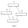
- FIG. 2 schematically illustrates the device for coupling position referencing and a schematic representation of the interacting components.
- the controller 60 selects the measurement and a retrievable Deposit of the measured coupling position causes.
- the determination of the standstill of the clutch and the clutch position measurement is carried out with the aid of a sensor 66, which is a Inkrementalwegmesssensor in a preferred embodiment.
- the control device 60 causes the activation of the clutch actuator 64, in particular of the actuator motor during the active period. Activation takes place by energizing the actuator motor. In a preferred embodiment, the control device causes energization in the form of jittering current.
- the control device causes energization, so that a force effect in the direction of clutch closing is effected by the clutch actuator 64.
- the energization takes place in a manner such that force action is caused in the direction of clutch opening.
- the control device 60 sets the last determined clutch position as the clutch reference position and verifies it. If it is determined by the control device 60 that only one or none of the two conditions is fulfilled, then the control device 60 causes the activation of the clutch actuator during the active period and the subsequent passive switching of the clutch actuator 64 during the passive period as well as the Clutch position determination is performed. The cycling of this process loop is initiated by the controller 60 until the two conditions are met and the controller 60 causes the loop to exit.
Landscapes
- Engineering & Computer Science (AREA)
- General Engineering & Computer Science (AREA)
- Physics & Mathematics (AREA)
- Fluid Mechanics (AREA)
- Mechanical Engineering (AREA)
- Electromagnetism (AREA)
- Hydraulic Clutches, Magnetic Clutches, Fluid Clutches, And Fluid Joints (AREA)
- Braking Arrangements (AREA)
- Mechanical Operated Clutches (AREA)
Claims (10)
- Procédé de commande d'un embrayage (62) non auto-rétentif pouvant être actionné au moyen d'un système d'actionneur d'embrayage (64) à partir d'une alimentation en courant, entre une unité d'entraînement et une transmission, avec un dispositif de commande (60) au moyen duquel sont effectuées une commande du système d'actionneur d'embrayage (64) et une détection de données de mesure d'un capteur (66) pour la détection d'une position d'embrayage, caractérisé en ce que pour vérifier une position de référence d'embrayage, le système d'actionneur d'embrayage (64) est commuté sans courant pendant un premier intervalle de temps passif prédéterminé ou jusqu'à l'apparition d'un arrêt de l'actionneur, et ensuite la position d'embrayage atteinte est déterminée au cours d'une première mesure, et une alimentation en courant du système d'actionneur d'embrayage (64) a lieu pendant un intervalle de temps actif prédéterminé et le système d'actionneur d'embrayage (64) est ensuite à nouveau commuté sans courant pendant un intervalle de temps passif supplémentaire prédéterminé ou jusqu'à l'apparition d'un arrêt de l'actionneur, et ensuite on détermine au cours d'une autre mesure la position d'embrayage et on vérifie ensuite si les positions d'embrayage mesurées peuvent être vérifiées en tant que nouvelle position de référence d'embrayage.
- Procédé selon la revendication 1, caractérisé en ce qu'après la réalisation de la première mesure, on effectue de manière cyclique, dans une boucle de processus au début de la boucle de processus pendant l'intervalle de temps actif prédéterminé une alimentation en courant du système d'actionneur d'embrayage (64) et le système d'actionneur d'embrayage (64) est ensuite commuté à nouveau sans courant pendant l'intervalle de temps passif supplémentaire prédéterminé ou jusqu'à l'apparition de l'arrêt de l'actionneur, et ensuite au cours d'une mesure supplémentaire, on détermine la position d'embrayage et l'on vérifie ensuite si l'une des positions d'embrayage mesurées peut être vérifiée en tant que nouvelle position de référence d'embrayage, et dans ce cas la boucle de processus est également terminée, et sinon, on revient au début de la boucle de processus et on l'exécute encore une fois.
- Procédé selon la revendication 2, caractérisé en ce que les dernières positions d'embrayage mesurées les plus récentes sont vérifiées en tant que position de référence d'embrayage, et l'on établit si les positions d'embrayage déterminées dans la dernière mesure et une mesure précédente coïncident et se situent à l'intérieur d'une plage de valeurs plausible pour la position de référence d'embrayage.
- Procédé selon la revendication 1, caractérisé en ce que pour l'intervalle de temps actif prédéterminé, il se produit une alimentation en courant du système d'actionneur d'embrayage (64) et le système d'actionneur d'embrayage (64) est ensuite commuté à nouveau sans courant pendant un deuxième intervalle de temps passif prédéterminé ou jusqu'à l'apparition d'un arrêt de l'actionneur, et ensuite, au cours d'une deuxième mesure, on détermine la position d'embrayage et ensuite on vérifie si la position d'embrayage mesurée peut être vérifiée en tant que nouvelle position de référence d'embrayage.
- Procédé selon la revendication 4, caractérisé en ce que la deuxième position d'embrayage mesurée est vérifiée en tant que position de référence d'embrayage et l'on établit si les positions d'embrayage déterminées au cours de la première et de la deuxième mesure coïncident et se situent à l'intérieur d'une plage de valeurs plausibles pour la position de référence d'embrayage.
- Procédé selon les revendications 1 à 5, caractérisé en ce que l'alimentation en courant du système d'actionneur d'embrayage (64) se produisant pendant l'intervalle de temps actif provoque une application de force dans la direction de la fermeture de l'embrayage.
- Procédé selon les revendications 1 à 5, caractérisé en ce que l'alimentation en courant du système d'actionneur d'embrayage (64) se produisant pendant l'intervalle de temps actif provoque une application de force dans la direction de l'ouverture de l'embrayage.
- Procédé selon les revendications 1 à 5, caractérisé en ce que l'alimentation en courant du système d'actionneur d'embrayage (64) se produisant pendant l'intervalle de temps actif provoque une application de force alternant dans le temps.
- Procédé selon les revendications 1 à 8, caractérisé en ce que l'alimentation en courant du système d'actionneur d'embrayage s'effectue seulement avec des tensions ou des courants qui n'entraînent aucune surcharge thermique des moteurs d'actionneur.
- Dispositif pour commander un embrayage (62) non auto-rétentif pouvant être actionné au moyen d'un système d'actionneur d'embrayage (64) à partir d'une alimentation en courant, entre une unité d'entraînement et une transmission, avec un dispositif de commande (60) au moyen duquel sont effectuées une commande du système d'actionneur d'embrayage (64) et une détection de données de mesure d'un capteur (66) pour la détection d'une position d'embrayage, caractérisé en ce que le dispositif de commande (60) est réalisé et conçu de telle sorte que la commande du système d'actionneur d'embrayage soit effectuée avec un procédé selon l'une quelconque des revendications 1 à 9.
Applications Claiming Priority (2)
| Application Number | Priority Date | Filing Date | Title |
|---|---|---|---|
| DE102005028844A DE102005028844B4 (de) | 2005-06-22 | 2005-06-22 | Verfahren und Vorrichtung zur Steuerung einer nicht selbsthaltenden Kupplung |
| PCT/DE2006/001041 WO2006136140A1 (fr) | 2005-06-22 | 2006-06-20 | Position de référence d'embrayage |
Publications (2)
| Publication Number | Publication Date |
|---|---|
| EP1896746A1 EP1896746A1 (fr) | 2008-03-12 |
| EP1896746B1 true EP1896746B1 (fr) | 2010-11-17 |
Family
ID=37011965
Family Applications (1)
| Application Number | Title | Priority Date | Filing Date |
|---|---|---|---|
| EP06753279A Not-in-force EP1896746B1 (fr) | 2005-06-22 | 2006-06-20 | Position de référence d'embrayage |
Country Status (8)
| Country | Link |
|---|---|
| US (1) | US7574296B2 (fr) |
| EP (1) | EP1896746B1 (fr) |
| JP (1) | JP5076116B2 (fr) |
| KR (1) | KR101267156B1 (fr) |
| CN (1) | CN101203690B (fr) |
| AT (1) | ATE488706T1 (fr) |
| DE (2) | DE102005028844B4 (fr) |
| WO (1) | WO2006136140A1 (fr) |
Families Citing this family (25)
| Publication number | Priority date | Publication date | Assignee | Title |
|---|---|---|---|---|
| DE102006003711A1 (de) * | 2006-01-26 | 2007-08-02 | Zf Friedrichshafen Ag | Verfahren zur Steuerung eines Kraftfahrzeug-Antriebsstrangs |
| EP1987264B1 (fr) * | 2006-02-16 | 2012-08-08 | Schaeffler Technologies AG & Co. KG | Procede et dispositif de reperage de la position d'un organe d'actionnement |
| DE102008033041A1 (de) | 2007-08-07 | 2009-02-12 | Luk Lamellen Und Kupplungsbau Beteiligungs Kg | Verfahren zur Plausibilisierung eines Referenzpunktes eines Hebelaktors |
| DE102008044823A1 (de) | 2007-09-10 | 2009-03-12 | Luk Lamellen Und Kupplungsbau Beteiligungs Kg | Verfahren zum Steuern einer Reibungskupplung |
| DE102009009999B4 (de) * | 2009-02-23 | 2012-09-13 | Getrag Getriebe- Und Zahnradfabrik Hermann Hagenmeyer Gmbh & Co. Kg | Kupplungssteuerverfahren |
| KR101684714B1 (ko) * | 2009-03-12 | 2016-12-08 | 섀플러 테크놀로지스 아게 운트 코. 카게 | 액추에이터 위치 포착 |
| DE102010014659A1 (de) * | 2009-05-05 | 2010-11-18 | Luk Lamellen Und Kupplungsbau Beteiligungs Kg | Sichere Kupplungsposition |
| KR20150067304A (ko) * | 2012-11-06 | 2015-06-17 | 혼다 기켄 고교 가부시키가이샤 | 고장 검지 장치 및 하이브리드 차량 |
| FR2998934B1 (fr) * | 2012-12-05 | 2016-04-01 | Peugeot Citroen Automobiles Sa | Dispositif et procede d'analyse de la validite d'une position apprise d'un point de lechage d'un embrayage |
| WO2014190987A1 (fr) | 2013-05-28 | 2014-12-04 | Schaeffler Technologies Gmbh & Co. Kg | Système d'actionnement d'embrayage |
| CN105339693A (zh) | 2013-06-27 | 2016-02-17 | 沃尔沃卡车集团 | 自动离合器校准 |
| CN104452191B (zh) * | 2013-09-18 | 2018-06-01 | 安徽聚隆传动科技股份有限公司 | 一种离合器及离合器控制方法 |
| DE102014223479B3 (de) * | 2014-11-18 | 2016-04-07 | Schaeffler Technologies AG & Co. KG | Verfahren zur Einstellung einer Anschlagposition eines hydrostatischen Kupplungsaktors |
| DE102015202827B3 (de) | 2015-02-17 | 2016-04-28 | Schaeffler Technologies AG & Co. KG | Aktor mit Planetenwälzgewindespindeltrieb |
| US10082184B2 (en) * | 2015-03-02 | 2018-09-25 | Rolls-Royce Corporation | System and method for eliminating adverse clutch vibratory responses |
| DE102017113965A1 (de) | 2017-06-23 | 2018-12-27 | Schaeffler Technologies AG & Co. KG | Verfahren zur Einstellung eines maximalen Verfahrweges eines Kupplungsaktors |
| CN109812519B (zh) * | 2017-11-22 | 2020-11-03 | 上海汽车集团股份有限公司 | 一种离合器控制方法、控制器以及控制系统 |
| DE102018100287B4 (de) | 2017-11-28 | 2024-04-25 | Schaeffler Technologies AG & Co. KG | Verfahren zum Ansteuern eines einen Elektromotor umfassenden Kupplungsaktors |
| DE102018104356A1 (de) | 2017-12-11 | 2019-06-13 | Schaeffler Technologies AG & Co. KG | Verfahren zur Steuerung einer Kupplung mit einer automatisierten Kupplungsbetätigung |
| DE102018128722A1 (de) * | 2018-11-15 | 2020-05-20 | Schaeffler Technologies AG & Co. KG | Verfahren zur Bestimmung einer Kennlinie einer Vorrichtung zur Betätigung eines Betätigungselements eines Fahrzeuges, vorzugsweise eines Pedalkraftsimulators |
| WO2021058053A1 (fr) | 2019-09-27 | 2021-04-01 | Schaeffler Technologies AG & Co. KG | Procédé pour commander un embrayage à friction et dispositif de transmission du couple pourvu de cet embrayage à friction |
| DE102021118067A1 (de) | 2020-10-12 | 2022-04-14 | Schaeffler Technologies AG & Co. KG | Verfahren zur Ansteuerung eines elektromagnetischen Aktuators und hydraulisches System mit Druckregelventilen zur Ansteuerung von hydraulischen Aktuatoren |
| WO2022106862A1 (fr) * | 2020-11-18 | 2022-05-27 | 日産自動車株式会社 | Procédé de commande d'embrayage de véhicule et dispositif de commande d'embrayage de véhicule |
| DE102021112647A1 (de) | 2021-05-17 | 2022-11-17 | Bayerische Motoren Werke Aktiengesellschaft | Verfahren und Vorrichtung zur Ermittlung der Kisspoint-Position einer Kupplung |
| KR102931330B1 (ko) | 2021-09-10 | 2026-02-25 | 현대자동차주식회사 | 클러치 제어 기준값 설정방법 |
Family Cites Families (48)
| Publication number | Priority date | Publication date | Assignee | Title |
|---|---|---|---|---|
| FR2526935A1 (fr) * | 1982-05-14 | 1983-11-18 | Thomson Csf | Procede et dispositif de mesure simultanee de caracteristiques geometriques d'une fibre optique |
| JPH0826901B2 (ja) * | 1987-10-31 | 1996-03-21 | いすゞ自動車株式会社 | クラッチ制御装置 |
| US5221983A (en) * | 1989-01-19 | 1993-06-22 | Bell Communications Research, Inc. | Passive photonic loop architecture employing wavelength multiplexing |
| DE3913300A1 (de) * | 1989-04-22 | 1990-10-25 | Standard Elektrik Lorenz Ag | Optisches nachrichtenuebertragungssystem fuer den teilnehmeranschlussbereich |
| US5251001A (en) * | 1991-11-18 | 1993-10-05 | Teradyne, Inc. | Reflected optical power fiber test system |
| US5276543A (en) * | 1991-11-22 | 1994-01-04 | Gte Laboratories Incorporated | Optical signal equalizer for wavelength division multiplexed optical fiber systems |
| US5321541A (en) * | 1991-12-12 | 1994-06-14 | At&T Bell Laboratories | Passive optical communication network with broadband upgrade |
| JP2751789B2 (ja) * | 1993-07-14 | 1998-05-18 | 日本電気株式会社 | 光ファイバ増幅器 |
| US5440417A (en) * | 1993-10-04 | 1995-08-08 | At&T Corp. | System for spectrum-sliced fiber amplifier light for multi-channel wavelength-division-multiplexed applications |
| US5550666A (en) * | 1994-06-17 | 1996-08-27 | Lucent Technologies Inc. | Wavelength division multiplexed multi-frequency optical source and broadband incoherent optical source |
| DE4433825C2 (de) * | 1994-09-22 | 1996-08-01 | Fichtel & Sachs Ag | Stelleinrichtung mit einer Kupplungslageregelung |
| US5680234A (en) * | 1994-10-20 | 1997-10-21 | Lucent Technologies Inc. | Passive optical network with bi-directional optical spectral slicing and loop-back |
| US5907417A (en) * | 1994-12-30 | 1999-05-25 | Lucent Technologies Inc. | Passive optical network with diagnostic loop-back |
| JPH08204636A (ja) * | 1995-01-25 | 1996-08-09 | Kokusai Denshin Denwa Co Ltd <Kdd> | 光通信システム |
| US5661585A (en) * | 1995-02-27 | 1997-08-26 | Lucent Technologies Inc. | Passive optical network having amplified LED transmitters |
| US5625478A (en) * | 1995-09-14 | 1997-04-29 | Lucent Technologies Inc. | Optically restorable WDM ring network using simple add/drop circuitry |
| US5646744A (en) * | 1996-01-11 | 1997-07-08 | Xerox Corporation | Show-through correction for two-sided documents |
| US5835517A (en) * | 1996-10-04 | 1998-11-10 | W. L. Gore & Associates, Inc. | WDM multiplexer-demultiplexer using Fabry-Perot filter array |
| NL1004667C2 (nl) * | 1996-12-02 | 1998-06-03 | Nederland Ptt | Optische systemen met een of meer gestabiliseerde lasersignaalbronnen. |
| US5880865A (en) * | 1996-12-03 | 1999-03-09 | Lucent Technologies Inc. | Wavelength-division-multiplexed network having broadcast capability |
| JP2985804B2 (ja) * | 1996-12-04 | 1999-12-06 | 日本電気株式会社 | 光pll回路 |
| US6304350B1 (en) * | 1997-05-27 | 2001-10-16 | Lucent Technologies Inc | Temperature compensated multi-channel, wavelength-division-multiplexed passive optical network |
| US6034799A (en) * | 1997-06-30 | 2000-03-07 | Lucent Technologies Inc. | Tuning source for lightwave systems |
| US6137611A (en) * | 1997-09-27 | 2000-10-24 | Lucent Technologies Inc. | Suppression of coherent rayleigh noise in bidirectional communication systems |
| JP3560797B2 (ja) * | 1997-12-22 | 2004-09-02 | 本田技研工業株式会社 | ロックアップクラッチ制御装置 |
| US6650840B2 (en) * | 1998-03-27 | 2003-11-18 | Lucent Technologies Inc. | Method for identifying faults in a branched optical network |
| KR100330409B1 (ko) * | 1998-07-23 | 2002-08-27 | 한국과학기술원 | 파장분할다중 방식 다중화/역다중화 장치와 이를 이용한 파장분할다중 방식 수동형 광 가입자망 |
| JP2000174397A (ja) * | 1998-12-02 | 2000-06-23 | Nec Corp | 多波長光源装置及びその発振周波数制御方法 |
| JP2000310800A (ja) * | 1999-02-23 | 2000-11-07 | Atr Adaptive Communications Res Lab | 2光信号発生器 |
| JP2000337542A (ja) * | 1999-05-28 | 2000-12-05 | Aisin Seiki Co Ltd | 比例電磁弁 |
| DE10027330A1 (de) * | 1999-06-08 | 2000-12-14 | Luk Lamellen & Kupplungsbau | Verfahren zum Betreiben einer Drehmoment-Übertragungseinrichtung |
| US6879619B1 (en) * | 1999-07-27 | 2005-04-12 | Intel Corporation | Method and apparatus for filtering an optical beam |
| DE19953292A1 (de) * | 1999-11-05 | 2001-05-10 | Mannesmann Sachs Ag | Verfahren zum Einlernen eines Aktuators für eine Kupplung und/oder ein Getriebe in einem Antriebsstrang |
| KR100325687B1 (ko) * | 1999-12-21 | 2002-02-25 | 윤덕용 | 주입된 비간섭성 광에 파장 잠김된 페브리-페롯 레이저다이오드를 이용한 파장분할 다중방식 광통신용 광원 |
| JP2001203643A (ja) * | 2000-01-21 | 2001-07-27 | Hitachi Ltd | 波長安定化光送信装置 |
| GB2380531B (en) * | 2000-02-15 | 2004-10-20 | Luk Lamellen & Kupplungsbau | Torque transfer device. |
| US6374410B2 (en) * | 2000-06-30 | 2002-04-23 | Robert Lynn Adamson | Knee pad for figure skating |
| JP2002135212A (ja) * | 2000-10-20 | 2002-05-10 | Fujitsu Ltd | 双方向伝送可能な光波長分割多重伝送システム |
| DE10052442C2 (de) * | 2000-10-23 | 2003-06-05 | Methode Electronics Malta Ltd | Stellvorrichtung für ein Fahrzeug mit einem mechanisch verstellbaren Bauteil und Verfahren zum Betreiben der Stellvorrichtung |
| KR100360769B1 (ko) * | 2000-12-05 | 2002-11-13 | 한국전자통신연구원 | 양방향 광분기삽입기 |
| US6628696B2 (en) * | 2001-01-19 | 2003-09-30 | Siros Technologies, Inc. | Multi-channel DWDM transmitter based on a vertical cavity surface emitting laser |
| US20040175188A1 (en) * | 2001-04-18 | 2004-09-09 | Antoine Bellemare | Optical sources and transmitters for optical telecommunications |
| US7116851B2 (en) * | 2001-10-09 | 2006-10-03 | Infinera Corporation | Optical signal receiver, an associated photonic integrated circuit (RxPIC), and method improving performance |
| EP1436931B1 (fr) * | 2001-10-09 | 2005-12-28 | Infinera Corporation | Architecture de reseau optique numerique |
| KR100454887B1 (ko) * | 2002-01-30 | 2004-11-06 | 한국과학기술원 | 파장분할 다중방식 수동 광 네트워크 장치 |
| US7006719B2 (en) * | 2002-03-08 | 2006-02-28 | Infinera Corporation | In-wafer testing of integrated optical components in photonic integrated circuits (PICs) |
| KR100515259B1 (ko) * | 2002-05-03 | 2005-09-15 | 한국과학기술원 | 파장 가변 광원 구현 방법 및 장치와 이 광원을 이용한 파장분할 다중방식 광전송 장치 |
| DE102004009832A1 (de) * | 2003-03-03 | 2004-09-16 | Luk Lamellen Und Kupplungsbau Beteiligungs Kg | Ausrücksysteme |
-
2005
- 2005-06-22 DE DE102005028844A patent/DE102005028844B4/de not_active Expired - Fee Related
-
2006
- 2006-06-20 JP JP2008517312A patent/JP5076116B2/ja not_active Expired - Fee Related
- 2006-06-20 EP EP06753279A patent/EP1896746B1/fr not_active Not-in-force
- 2006-06-20 WO PCT/DE2006/001041 patent/WO2006136140A1/fr not_active Ceased
- 2006-06-20 AT AT06753279T patent/ATE488706T1/de active
- 2006-06-20 KR KR1020077023300A patent/KR101267156B1/ko not_active Expired - Fee Related
- 2006-06-20 DE DE502006008341T patent/DE502006008341D1/de active Active
- 2006-06-20 CN CN2006800225776A patent/CN101203690B/zh not_active Expired - Fee Related
-
2007
- 2007-12-21 US US12/004,669 patent/US7574296B2/en not_active Expired - Fee Related
Also Published As
| Publication number | Publication date |
|---|---|
| JP5076116B2 (ja) | 2012-11-21 |
| US20080215221A1 (en) | 2008-09-04 |
| KR20080017295A (ko) | 2008-02-26 |
| DE102005028844B4 (de) | 2007-07-05 |
| ATE488706T1 (de) | 2010-12-15 |
| US7574296B2 (en) | 2009-08-11 |
| CN101203690B (zh) | 2010-04-14 |
| DE102005028844A1 (de) | 2007-01-11 |
| EP1896746A1 (fr) | 2008-03-12 |
| JP2008546961A (ja) | 2008-12-25 |
| CN101203690A (zh) | 2008-06-18 |
| WO2006136140A1 (fr) | 2006-12-28 |
| DE502006008341D1 (de) | 2010-12-30 |
| KR101267156B1 (ko) | 2013-05-23 |
Similar Documents
| Publication | Publication Date | Title |
|---|---|---|
| DE102005028844B4 (de) | Verfahren und Vorrichtung zur Steuerung einer nicht selbsthaltenden Kupplung | |
| EP2214944B1 (fr) | Frein de stationnement et procédé de fonctionnement | |
| EP1594715B1 (fr) | Procede pour determiner le point d'application de l'embrayage d'une boite de vitesse automatique | |
| DE102018203166A1 (de) | Parksperre in einem Getriebe eines Kraftfahrzeugs | |
| DE102014226856B4 (de) | Verfahren und Vorrichtung zum Betreiben einer Bremseinrichtung, Bremseinrichtung | |
| DE19823089A1 (de) | Verfahren und Vorrichtung zur Steuerung einer Kupplung | |
| DE112010001147B4 (de) | Verfahren und Vorrichtung zum Betreiben einer Antriebseinrichtung zum Verstellen einer automatisierten Kupplung | |
| EP1521917B1 (fr) | Procede et dispositif permettant d'ameliorer la securite de fonctionnement lors de l'actionnement d'un embrayage et/ou d'une boite de vitesses | |
| EP2150718A1 (fr) | Procédé et dispositif de commande d'un embrayage | |
| EP1614922A2 (fr) | Méthode et dispositif pour référencer un capteur incrémentiel de position dans un dispositif d'actuation controllé électroniquement d'un embrayage | |
| DE102015113517A1 (de) | Verfahren zur Steuerung eines motorischen Klappenantriebs und Klappenantrieb zur Einstellung eines Fluidstroms | |
| WO2007079950A1 (fr) | Procédé pour contrôler une fonction de freinage d'un moteur de robot | |
| EP2025964B1 (fr) | Procédé de vérification d'un point de référence d'un actionneur de levier | |
| WO2001063136A1 (fr) | Embrayage automatique pour vehicule automobile, et procede de commande d'un embrayage de vehicule automobile | |
| DE102021207816B3 (de) | Verfahren zum Betätigen einer formschlüssigen Kupplung eines Getriebes sowie Kupplungsvorrichtung | |
| EP1770313A2 (fr) | Procédé et dispositf destinés à l'utilisation d'un dispositif d'entraînement | |
| EP1760349B1 (fr) | Dispositif pour controler une variation de position d'un moteur électrique sans balais | |
| EP3959486B1 (fr) | Procédé de réglage de la position d'un actionneur après une interruption de l'alimentation électrique | |
| DE102005006912A1 (de) | Verfahren zum Abgleichen einer Inkrementalwegmessung und zum Erkennen eines Anschlages bei einer Bewegungsübertragung einer Inkrementalwegmessung sowie Vorrichtung zum Durchführen der Verfahren | |
| DE102011087926A1 (de) | Stellantrieb einer Luftdurchlassvorrichtung | |
| DE10139243B4 (de) | Verfahren zur Überwachung eines elektromagnetisch betriebenen Aktors sowie elektromagnetisch betriebene Kupplung oder Bremse | |
| EP1727274B1 (fr) | Procédé et dispositif de fonctionnement d'un servomoteur | |
| EP1835195A2 (fr) | Procédé pour commander un actionneur à moteur électrique d'un embrayage ou d'une transmission | |
| DE102005030185A1 (de) | Verfahren und Vorrichtung zum Referenzieren eines Inkrementalwegsensors in einer elektronisch gesteuerten Betätigungsvorrichtung einer Kupplung | |
| DE102006043075A1 (de) | Verfahren und Vorrichtung zum Betreiben einer Antriebseinrichtung |
Legal Events
| Date | Code | Title | Description |
|---|---|---|---|
| PUAI | Public reference made under article 153(3) epc to a published international application that has entered the european phase |
Free format text: ORIGINAL CODE: 0009012 |
|
| 17P | Request for examination filed |
Effective date: 20080122 |
|
| AK | Designated contracting states |
Kind code of ref document: A1 Designated state(s): AT BE BG CH CY CZ DE DK EE ES FI FR GB GR HU IE IS IT LI LT LU LV MC NL PL PT RO SE SI SK TR |
|
| DAX | Request for extension of the european patent (deleted) | ||
| RIN1 | Information on inventor provided before grant (corrected) |
Inventor name: MARTIN, JENS Inventor name: BAEHR, MARKUS Inventor name: FUSS, MARTIN Inventor name: SCHWEIZER, ALEXANDER Inventor name: ZIMMERMANN, MARTIN Inventor name: DREHER, FELIX Inventor name: PANZER, MATTHIAS Inventor name: STENGEL, FRANK Inventor name: EHRLICH, MATTHIAS |
|
| DAX | Request for extension of the european patent (deleted) | ||
| GRAP | Despatch of communication of intention to grant a patent |
Free format text: ORIGINAL CODE: EPIDOSNIGR1 |
|
| GRAS | Grant fee paid |
Free format text: ORIGINAL CODE: EPIDOSNIGR3 |
|
| RAP1 | Party data changed (applicant data changed or rights of an application transferred) |
Owner name: SCHAEFFLER TECHNOLOGIES GMBH & CO. KG |
|
| GRAA | (expected) grant |
Free format text: ORIGINAL CODE: 0009210 |
|
| AK | Designated contracting states |
Kind code of ref document: B1 Designated state(s): AT BE BG CH CY CZ DE DK EE ES FI FR GB GR HU IE IS IT LI LT LU LV MC NL PL PT RO SE SI SK TR |
|
| REG | Reference to a national code |
Ref country code: GB Ref legal event code: FG4D Free format text: NOT ENGLISH |
|
| REG | Reference to a national code |
Ref country code: CH Ref legal event code: EP |
|
| REG | Reference to a national code |
Ref country code: IE Ref legal event code: FG4D |
|
| REF | Corresponds to: |
Ref document number: 502006008341 Country of ref document: DE Date of ref document: 20101230 Kind code of ref document: P |
|
| REG | Reference to a national code |
Ref country code: NL Ref legal event code: VDEP Effective date: 20101117 |
|
| LTIE | Lt: invalidation of european patent or patent extension |
Effective date: 20101117 |
|
| PG25 | Lapsed in a contracting state [announced via postgrant information from national office to epo] |
Ref country code: LT Free format text: LAPSE BECAUSE OF FAILURE TO SUBMIT A TRANSLATION OF THE DESCRIPTION OR TO PAY THE FEE WITHIN THE PRESCRIBED TIME-LIMIT Effective date: 20101117 |
|
| PG25 | Lapsed in a contracting state [announced via postgrant information from national office to epo] |
Ref country code: LV Free format text: LAPSE BECAUSE OF FAILURE TO SUBMIT A TRANSLATION OF THE DESCRIPTION OR TO PAY THE FEE WITHIN THE PRESCRIBED TIME-LIMIT Effective date: 20101117 Ref country code: FI Free format text: LAPSE BECAUSE OF FAILURE TO SUBMIT A TRANSLATION OF THE DESCRIPTION OR TO PAY THE FEE WITHIN THE PRESCRIBED TIME-LIMIT Effective date: 20101117 Ref country code: NL Free format text: LAPSE BECAUSE OF FAILURE TO SUBMIT A TRANSLATION OF THE DESCRIPTION OR TO PAY THE FEE WITHIN THE PRESCRIBED TIME-LIMIT Effective date: 20101117 Ref country code: CY Free format text: LAPSE BECAUSE OF FAILURE TO SUBMIT A TRANSLATION OF THE DESCRIPTION OR TO PAY THE FEE WITHIN THE PRESCRIBED TIME-LIMIT Effective date: 20101117 Ref country code: PT Free format text: LAPSE BECAUSE OF FAILURE TO SUBMIT A TRANSLATION OF THE DESCRIPTION OR TO PAY THE FEE WITHIN THE PRESCRIBED TIME-LIMIT Effective date: 20110317 Ref country code: SI Free format text: LAPSE BECAUSE OF FAILURE TO SUBMIT A TRANSLATION OF THE DESCRIPTION OR TO PAY THE FEE WITHIN THE PRESCRIBED TIME-LIMIT Effective date: 20101117 Ref country code: IS Free format text: LAPSE BECAUSE OF FAILURE TO SUBMIT A TRANSLATION OF THE DESCRIPTION OR TO PAY THE FEE WITHIN THE PRESCRIBED TIME-LIMIT Effective date: 20110317 Ref country code: SE Free format text: LAPSE BECAUSE OF FAILURE TO SUBMIT A TRANSLATION OF THE DESCRIPTION OR TO PAY THE FEE WITHIN THE PRESCRIBED TIME-LIMIT Effective date: 20101117 Ref country code: BG Free format text: LAPSE BECAUSE OF FAILURE TO SUBMIT A TRANSLATION OF THE DESCRIPTION OR TO PAY THE FEE WITHIN THE PRESCRIBED TIME-LIMIT Effective date: 20110217 |
|
| REG | Reference to a national code |
Ref country code: IE Ref legal event code: FD4D |
|
| PG25 | Lapsed in a contracting state [announced via postgrant information from national office to epo] |
Ref country code: GR Free format text: LAPSE BECAUSE OF FAILURE TO SUBMIT A TRANSLATION OF THE DESCRIPTION OR TO PAY THE FEE WITHIN THE PRESCRIBED TIME-LIMIT Effective date: 20110218 |
|
| PG25 | Lapsed in a contracting state [announced via postgrant information from national office to epo] |
Ref country code: CZ Free format text: LAPSE BECAUSE OF FAILURE TO SUBMIT A TRANSLATION OF THE DESCRIPTION OR TO PAY THE FEE WITHIN THE PRESCRIBED TIME-LIMIT Effective date: 20101117 Ref country code: EE Free format text: LAPSE BECAUSE OF FAILURE TO SUBMIT A TRANSLATION OF THE DESCRIPTION OR TO PAY THE FEE WITHIN THE PRESCRIBED TIME-LIMIT Effective date: 20101117 Ref country code: ES Free format text: LAPSE BECAUSE OF FAILURE TO SUBMIT A TRANSLATION OF THE DESCRIPTION OR TO PAY THE FEE WITHIN THE PRESCRIBED TIME-LIMIT Effective date: 20110228 Ref country code: IE Free format text: LAPSE BECAUSE OF FAILURE TO SUBMIT A TRANSLATION OF THE DESCRIPTION OR TO PAY THE FEE WITHIN THE PRESCRIBED TIME-LIMIT Effective date: 20101117 |
|
| PG25 | Lapsed in a contracting state [announced via postgrant information from national office to epo] |
Ref country code: DK Free format text: LAPSE BECAUSE OF FAILURE TO SUBMIT A TRANSLATION OF THE DESCRIPTION OR TO PAY THE FEE WITHIN THE PRESCRIBED TIME-LIMIT Effective date: 20101117 Ref country code: SK Free format text: LAPSE BECAUSE OF FAILURE TO SUBMIT A TRANSLATION OF THE DESCRIPTION OR TO PAY THE FEE WITHIN THE PRESCRIBED TIME-LIMIT Effective date: 20101117 Ref country code: PL Free format text: LAPSE BECAUSE OF FAILURE TO SUBMIT A TRANSLATION OF THE DESCRIPTION OR TO PAY THE FEE WITHIN THE PRESCRIBED TIME-LIMIT Effective date: 20101117 Ref country code: RO Free format text: LAPSE BECAUSE OF FAILURE TO SUBMIT A TRANSLATION OF THE DESCRIPTION OR TO PAY THE FEE WITHIN THE PRESCRIBED TIME-LIMIT Effective date: 20101117 |
|
| PLBE | No opposition filed within time limit |
Free format text: ORIGINAL CODE: 0009261 |
|
| STAA | Information on the status of an ep patent application or granted ep patent |
Free format text: STATUS: NO OPPOSITION FILED WITHIN TIME LIMIT |
|
| 26N | No opposition filed |
Effective date: 20110818 |
|
| REG | Reference to a national code |
Ref country code: DE Ref legal event code: R097 Ref document number: 502006008341 Country of ref document: DE Effective date: 20110818 |
|
| PG25 | Lapsed in a contracting state [announced via postgrant information from national office to epo] |
Ref country code: IT Free format text: LAPSE BECAUSE OF FAILURE TO SUBMIT A TRANSLATION OF THE DESCRIPTION OR TO PAY THE FEE WITHIN THE PRESCRIBED TIME-LIMIT Effective date: 20101117 |
|
| BERE | Be: lapsed |
Owner name: SCHAEFFLER TECHNOLOGIES G.M.B.H. & CO. KG Effective date: 20110630 |
|
| REG | Reference to a national code |
Ref country code: CH Ref legal event code: PL |
|
| GBPC | Gb: european patent ceased through non-payment of renewal fee |
Effective date: 20110620 |
|
| PG25 | Lapsed in a contracting state [announced via postgrant information from national office to epo] |
Ref country code: BE Free format text: LAPSE BECAUSE OF NON-PAYMENT OF DUE FEES Effective date: 20110630 |
|
| PG25 | Lapsed in a contracting state [announced via postgrant information from national office to epo] |
Ref country code: CH Free format text: LAPSE BECAUSE OF NON-PAYMENT OF DUE FEES Effective date: 20110630 Ref country code: LI Free format text: LAPSE BECAUSE OF NON-PAYMENT OF DUE FEES Effective date: 20110630 |
|
| PG25 | Lapsed in a contracting state [announced via postgrant information from national office to epo] |
Ref country code: GB Free format text: LAPSE BECAUSE OF NON-PAYMENT OF DUE FEES Effective date: 20110620 |
|
| REG | Reference to a national code |
Ref country code: DE Ref legal event code: R081 Ref document number: 502006008341 Country of ref document: DE Owner name: SCHAEFFLER TECHNOLOGIES AG & CO. KG, DE Free format text: FORMER OWNER: SCHAEFFLER TECHNOLOGIES GMBH & CO. KG, 91074 HERZOGENAURACH, DE Effective date: 20120828 Ref country code: DE Ref legal event code: R081 Ref document number: 502006008341 Country of ref document: DE Owner name: SCHAEFFLER TECHNOLOGIES GMBH & CO. KG, DE Free format text: FORMER OWNER: SCHAEFFLER TECHNOLOGIES GMBH & CO. KG, 91074 HERZOGENAURACH, DE Effective date: 20120828 |
|
| REG | Reference to a national code |
Ref country code: AT Ref legal event code: MM01 Ref document number: 488706 Country of ref document: AT Kind code of ref document: T Effective date: 20110620 |
|
| PG25 | Lapsed in a contracting state [announced via postgrant information from national office to epo] |
Ref country code: AT Free format text: LAPSE BECAUSE OF NON-PAYMENT OF DUE FEES Effective date: 20110620 |
|
| PG25 | Lapsed in a contracting state [announced via postgrant information from national office to epo] |
Ref country code: MC Free format text: LAPSE BECAUSE OF NON-PAYMENT OF DUE FEES Effective date: 20110630 |
|
| PG25 | Lapsed in a contracting state [announced via postgrant information from national office to epo] |
Ref country code: LU Free format text: LAPSE BECAUSE OF NON-PAYMENT OF DUE FEES Effective date: 20110620 |
|
| PG25 | Lapsed in a contracting state [announced via postgrant information from national office to epo] |
Ref country code: TR Free format text: LAPSE BECAUSE OF FAILURE TO SUBMIT A TRANSLATION OF THE DESCRIPTION OR TO PAY THE FEE WITHIN THE PRESCRIBED TIME-LIMIT Effective date: 20101117 |
|
| PG25 | Lapsed in a contracting state [announced via postgrant information from national office to epo] |
Ref country code: HU Free format text: LAPSE BECAUSE OF FAILURE TO SUBMIT A TRANSLATION OF THE DESCRIPTION OR TO PAY THE FEE WITHIN THE PRESCRIBED TIME-LIMIT Effective date: 20101117 |
|
| REG | Reference to a national code |
Ref country code: DE Ref legal event code: R081 Ref document number: 502006008341 Country of ref document: DE Owner name: SCHAEFFLER TECHNOLOGIES GMBH & CO. KG, DE Free format text: FORMER OWNER: SCHAEFFLER TECHNOLOGIES AG & CO. KG, 91074 HERZOGENAURACH, DE Effective date: 20140212 Ref country code: DE Ref legal event code: R081 Ref document number: 502006008341 Country of ref document: DE Owner name: SCHAEFFLER TECHNOLOGIES AG & CO. KG, DE Free format text: FORMER OWNER: SCHAEFFLER TECHNOLOGIES AG & CO. KG, 91074 HERZOGENAURACH, DE Effective date: 20140212 |
|
| REG | Reference to a national code |
Ref country code: DE Ref legal event code: R081 Ref document number: 502006008341 Country of ref document: DE Owner name: SCHAEFFLER TECHNOLOGIES AG & CO. KG, DE Free format text: FORMER OWNER: SCHAEFFLER TECHNOLOGIES GMBH & CO. KG, 91074 HERZOGENAURACH, DE Effective date: 20150123 |
|
| REG | Reference to a national code |
Ref country code: FR Ref legal event code: PLFP Year of fee payment: 10 |
|
| REG | Reference to a national code |
Ref country code: FR Ref legal event code: PLFP Year of fee payment: 11 |
|
| REG | Reference to a national code |
Ref country code: FR Ref legal event code: PLFP Year of fee payment: 12 |
|
| PGFP | Annual fee paid to national office [announced via postgrant information from national office to epo] |
Ref country code: FR Payment date: 20170629 Year of fee payment: 12 |
|
| PGFP | Annual fee paid to national office [announced via postgrant information from national office to epo] |
Ref country code: DE Payment date: 20170831 Year of fee payment: 12 |
|
| REG | Reference to a national code |
Ref country code: DE Ref legal event code: R119 Ref document number: 502006008341 Country of ref document: DE |
|
| PG25 | Lapsed in a contracting state [announced via postgrant information from national office to epo] |
Ref country code: DE Free format text: LAPSE BECAUSE OF NON-PAYMENT OF DUE FEES Effective date: 20190101 Ref country code: FR Free format text: LAPSE BECAUSE OF NON-PAYMENT OF DUE FEES Effective date: 20180630 |
|
| P01 | Opt-out of the competence of the unified patent court (upc) registered |
Effective date: 20230523 |