EP1896747B1 - Verfahren zur steuerung einer kopplungsvorrichtung zwischen einer eingangswelle und einer ausgangswelle - Google Patents
Verfahren zur steuerung einer kopplungsvorrichtung zwischen einer eingangswelle und einer ausgangswelle Download PDFInfo
- Publication number
- EP1896747B1 EP1896747B1 EP06778971A EP06778971A EP1896747B1 EP 1896747 B1 EP1896747 B1 EP 1896747B1 EP 06778971 A EP06778971 A EP 06778971A EP 06778971 A EP06778971 A EP 06778971A EP 1896747 B1 EP1896747 B1 EP 1896747B1
- Authority
- EP
- European Patent Office
- Prior art keywords
- law
- xemb
- clutch
- coupling device
- interpolation
- Prior art date
- Legal status (The legal status is an assumption and is not a legal conclusion. Google has not performed a legal analysis and makes no representation as to the accuracy of the status listed.)
- Ceased
Links
Images

Classifications
-
- F—MECHANICAL ENGINEERING; LIGHTING; HEATING; WEAPONS; BLASTING
- F16—ENGINEERING ELEMENTS AND UNITS; GENERAL MEASURES FOR PRODUCING AND MAINTAINING EFFECTIVE FUNCTIONING OF MACHINES OR INSTALLATIONS; THERMAL INSULATION IN GENERAL
- F16D—COUPLINGS FOR TRANSMITTING ROTATION; CLUTCHES; BRAKES
- F16D48/00—External control of clutches
- F16D48/06—Control by electric or electronic means, e.g. of fluid pressure
-
- B—PERFORMING OPERATIONS; TRANSPORTING
- B60—VEHICLES IN GENERAL
- B60K—ARRANGEMENT OR MOUNTING OF PROPULSION UNITS OR OF TRANSMISSIONS IN VEHICLES; ARRANGEMENT OR MOUNTING OF PLURAL DIVERSE PRIME-MOVERS IN VEHICLES; AUXILIARY DRIVES FOR VEHICLES; INSTRUMENTATION OR DASHBOARDS FOR VEHICLES; ARRANGEMENTS IN CONNECTION WITH COOLING, AIR INTAKE, GAS EXHAUST OR FUEL SUPPLY OF PROPULSION UNITS IN VEHICLES
- B60K6/00—Arrangement or mounting of plural diverse prime-movers for mutual or common propulsion, e.g. hybrid propulsion systems comprising electric motors and internal combustion engines
- B60K6/20—Arrangement or mounting of plural diverse prime-movers for mutual or common propulsion, e.g. hybrid propulsion systems comprising electric motors and internal combustion engines the prime-movers consisting of electric motors and internal combustion engines, e.g. HEVs
- B60K6/22—Arrangement or mounting of plural diverse prime-movers for mutual or common propulsion, e.g. hybrid propulsion systems comprising electric motors and internal combustion engines the prime-movers consisting of electric motors and internal combustion engines, e.g. HEVs characterised by apparatus, components or means specially adapted for HEVs
- B60K6/38—Arrangement or mounting of plural diverse prime-movers for mutual or common propulsion, e.g. hybrid propulsion systems comprising electric motors and internal combustion engines the prime-movers consisting of electric motors and internal combustion engines, e.g. HEVs characterised by apparatus, components or means specially adapted for HEVs characterised by the driveline clutches
- B60K6/387—Actuated clutches, i.e. clutches engaged or disengaged by electric, hydraulic or mechanical actuating means
-
- F—MECHANICAL ENGINEERING; LIGHTING; HEATING; WEAPONS; BLASTING
- F16—ENGINEERING ELEMENTS AND UNITS; GENERAL MEASURES FOR PRODUCING AND MAINTAINING EFFECTIVE FUNCTIONING OF MACHINES OR INSTALLATIONS; THERMAL INSULATION IN GENERAL
- F16D—COUPLINGS FOR TRANSMITTING ROTATION; CLUTCHES; BRAKES
- F16D2500/00—External control of clutches by electric or electronic means
- F16D2500/10—System to be controlled
- F16D2500/104—Clutch
- F16D2500/10406—Clutch position
- F16D2500/10412—Transmission line of a vehicle
-
- F—MECHANICAL ENGINEERING; LIGHTING; HEATING; WEAPONS; BLASTING
- F16—ENGINEERING ELEMENTS AND UNITS; GENERAL MEASURES FOR PRODUCING AND MAINTAINING EFFECTIVE FUNCTIONING OF MACHINES OR INSTALLATIONS; THERMAL INSULATION IN GENERAL
- F16D—COUPLINGS FOR TRANSMITTING ROTATION; CLUTCHES; BRAKES
- F16D2500/00—External control of clutches by electric or electronic means
- F16D2500/10—System to be controlled
- F16D2500/104—Clutch
- F16D2500/10443—Clutch type
- F16D2500/1045—Friction clutch
-
- F—MECHANICAL ENGINEERING; LIGHTING; HEATING; WEAPONS; BLASTING
- F16—ENGINEERING ELEMENTS AND UNITS; GENERAL MEASURES FOR PRODUCING AND MAINTAINING EFFECTIVE FUNCTIONING OF MACHINES OR INSTALLATIONS; THERMAL INSULATION IN GENERAL
- F16D—COUPLINGS FOR TRANSMITTING ROTATION; CLUTCHES; BRAKES
- F16D2500/00—External control of clutches by electric or electronic means
- F16D2500/10—System to be controlled
- F16D2500/106—Engine
- F16D2500/1066—Hybrid
-
- F—MECHANICAL ENGINEERING; LIGHTING; HEATING; WEAPONS; BLASTING
- F16—ENGINEERING ELEMENTS AND UNITS; GENERAL MEASURES FOR PRODUCING AND MAINTAINING EFFECTIVE FUNCTIONING OF MACHINES OR INSTALLATIONS; THERMAL INSULATION IN GENERAL
- F16D—COUPLINGS FOR TRANSMITTING ROTATION; CLUTCHES; BRAKES
- F16D2500/00—External control of clutches by electric or electronic means
- F16D2500/30—Signal inputs
- F16D2500/302—Signal inputs from the actuator
- F16D2500/3026—Stroke
-
- F—MECHANICAL ENGINEERING; LIGHTING; HEATING; WEAPONS; BLASTING
- F16—ENGINEERING ELEMENTS AND UNITS; GENERAL MEASURES FOR PRODUCING AND MAINTAINING EFFECTIVE FUNCTIONING OF MACHINES OR INSTALLATIONS; THERMAL INSULATION IN GENERAL
- F16D—COUPLINGS FOR TRANSMITTING ROTATION; CLUTCHES; BRAKES
- F16D2500/00—External control of clutches by electric or electronic means
- F16D2500/70—Details about the implementation of the control system
- F16D2500/702—Look-up tables
- F16D2500/70252—Clutch torque
- F16D2500/70264—Stroke
-
- F—MECHANICAL ENGINEERING; LIGHTING; HEATING; WEAPONS; BLASTING
- F16—ENGINEERING ELEMENTS AND UNITS; GENERAL MEASURES FOR PRODUCING AND MAINTAINING EFFECTIVE FUNCTIONING OF MACHINES OR INSTALLATIONS; THERMAL INSULATION IN GENERAL
- F16D—COUPLINGS FOR TRANSMITTING ROTATION; CLUTCHES; BRAKES
- F16D2500/00—External control of clutches by electric or electronic means
- F16D2500/70—Details about the implementation of the control system
- F16D2500/706—Strategy of control
- F16D2500/70605—Adaptive correction; Modifying control system parameters, e.g. gains, constants, look-up tables
Definitions
- the present invention relates to controlling a coupling device between an input shaft driven by a motor and an output shaft capable of transmitting a maximum torque as a function of the position of an actuator of the coupling device according to a law. behavior of the coupling means.
- a hybrid traction system consisting for example of a heat engine coupled to an electric machine via a clutch, and driving an input shaft into a gearbox which drives the same.
- Wheels of a motor vehicle requires driving in torque of the motor organs, namely the engine and the electric machine, so as to best respect the will of the driver expressed in the form of torques to provide the wheel.
- the torque to be supplied to the wheel is distributed between the engine and the electric machine according to the particular operating conditions of the vehicle, in particular to optimize the energy consumption of the power train.
- This assembly In order to control this assembly, it is necessary to vary the distribution of the torque between the heat engine and the electric machine. This requires to be able to couple and decouple the engine and the electrical machine using a coupling means between the engine and the electric machine.
- This coupling member which is generally a friction clutch, must be controlled so as to accurately determine at least during slip periods, the torque that is transmitted by the clutch.
- Conventional traction chains also include coupling / decoupling means that can be controlled.
- the control must also control the transmitted torque, in particular during start-up or during transmission gearbox changes.
- the object of the present invention is to remedy this drawback by proposing a means for adapting the behavior laws of the clutch according to the use of the clutch so as to have, at each moment, the best possible modeling of the clutch. clutch behavior to get a good control of the clutch.
- the subject of the invention is a method for controlling a coupling device between an input shaft driven by a motor and a shaft. output, able to transmit a maximum torque depending on the position of an actuator of the coupling device, according to claim 1.
- the constitutive law at each instant of the coupling device is equal to the intermediate behavior law at each instant of the coupling device.
- the first law of reference is the constitutive law of the coupling means when it is new and cold and the second law of reference is the constitutive law of the coupling means when it is new and hot.
- an interpolation is performed between the intermediate behavior law and a third reference law corresponding to the used coupling device, by using an interpolation coefficient ⁇ , which is adapted by using a second gain K ⁇ , of a sign contrary to the first K ⁇ gain and small in absolute value compared to the first gain.
- the adaptation of the second interpolation coefficient ⁇ is carried out continuously throughout the lifetime of the coupling device and the adaptation of the first coupling coefficient is made, the period of use of the device per period of time. use, resetting it at the beginning of each usage period.
- the coupling device is for example a controlled clutch and can be incorporated in a traction chain, in particular a hybrid power train, of a motor vehicle.
- the invention also relates to a coupling device comprising the control means adapted to implement the method according to the invention.
- the coupling device is, for example, incorporated into the drive train of a motor vehicle.
- control device 2 which delivers to the clutch a positioning instruction of the control device of the clutch Xemb, cons.
- This device 2 for controlling the clutch receives as input a torque setpoint for the clutch Cemb, cons.
- the clutch control device 2 comprises a first so-called closed loop which makes it possible to estimate the torque effectively transmitted by the clutch when the clutch it operates in sliding mode, from a measurement of the actual position of the actuator of the clutch Xemb, mes and measurements of the engine torque Cmot and the engine speed Wmot of the drive motor of the input torque of the input shaft of the clutch, this estimator giving a magnitude Cemb, bf which is compared to the clutch setpoint provided by the drive system of the drive train.
- Such an estimator which uses in particular a modeling of the dynamic behavior of the traction chain, is known in itself to those skilled in the art.
- the torque setpoint for the clutch Cemb, cons and the closed-loop estimation of the torque effectively transmitted by the clutch Cemb, bf are compared in a first comparator 4 which makes the difference between these two pairs.
- This difference is sent as input to a calculation module of a regulation torque Cemb, r which is the instruction of torque that will be used to determine the adjustment positioning setpoint of the control means of the clutch.
- a regulation torque Cemb, r is the instruction of torque that will be used to determine the adjustment positioning setpoint of the control means of the clutch.
- the regulation torque Cemb, r is converted by a module 6 into a position setpoint for the actuator of the clutch Xemb, cons.
- the module 6 uses a behavior law of the clutch at time t Cemb (Xemb; t) which determines the relationship between the maximum torque transmissible by the clutch and the position of the control member.
- the position setpoint of the actuator Xemb, cons is sent into a module 7 for dynamic modeling of the clutch which takes into account the dynamic positioning of the clutch action means, and therefore takes into account the offsets. in time, to determine the theoretical position of the control member of the clutch at time t.
- This value is then transformed by a module 6 'which uses the same constitutive law of the clutch as the module 6, in an open loop estimate Cemb, bo of the maximum torque that could transmit the clutch at time t.
- the law used by the modules 6, 6 'and 6 is adapted by means of a self-adaptation procedure which takes into account a comparison in a comparator 8, of the open-loop estimation Cemb, bo of the maximum torque that can transmit the clutch at time t, and of the closed-loop estimation of the torque effectively transmitted by the clutch to the instant t Cemb, bf
- the difference between these two open-loop and closed-loop estimates of the torque transmissible or transmitted by the clutch is used to adapt the behavior laws of the clutch using a module 9d. self-adaptation using procedures of the type integration using gains that can be adjusted for the behavior desired for adaptation.
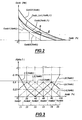
- Cemb1 (Xemb) which represents the law of behavior of the clutch when it is new and cold, that is to say when the linings are not worn or heated by a use.
- Cemb2 (Xemb) is also considered, which corresponds to the behavior of the hot new clutch, that is to say of the new clutch when it has been used and that it is at its maximum temperature of use.
- Cemb, int, (Xemb, t) corresponds to the constitutive law of the clutch in new condition under the actual conditions of use.
- a third law Cemb3 (Xemb) is used, which corresponds to the law of behavior of the clutch when it is worn and which is shifted with respect to the other laws, in particular because of the wear of the lining of the clutch which modifies therefore the geometry of the clutch.
- This law is characterized by the fact that the point of contact of the two plates of the clutch is substantially offset from what it is when the clutch is new.
- the stiffness of the control mechanism and the characteristics of the friction materials change over the life of the clutch.
- a law Cemb (Xemb, t) obtained by interpolation is used. between the intermediate law of behavior of the clutch and the law of behavior of the used clutch.
- an interpolation coefficient ⁇ is used which is such that at maximum torque transmissible by the given clutch, the position Xemb of the control means of the effective clutch is obtained by a linear interpolation between the instructions of positioning the clutch control means, on the one hand, when the clutch is completely worn and, on the other hand, when the clutch follows the intermediate behavior law of the clutch as it comes from to be defined.
- the estimation of the open loop torque corresponds to the value calculated from the estimated behavior of the clutch, and the closed loop estimate is close to the actual torque.
- the closed-loop estimation is greater than the open-loop estimate, it can be concluded that the estimated behavior of the clutch underestimates the torque transmitted by the clutch.
- the calculated torque for the cold clutch is less than the calculated torque for the hot clutch.
- a procedure is introduced in the regulation system for adapting the interpolation function ⁇ which consists of changing this function so that the derivative with respect to the time of the value of the function ⁇ is proportional to the difference found between the estimation of the closed loop torque and the estimation of the open loop torque.
- the coefficient of proportionality is a gain K ⁇ .
- the coefficient ⁇ is used to adapt a law which is such that the derivative of the coefficient ⁇ with respect to time is proportional to the difference observed between the estimate of the closed-loop torque and the estimate of the open-loop torque, with a coefficient of proportionality, or gain K ⁇ much smaller in absolute values than the coefficient K ⁇ and opposite sign to the coefficient K ⁇ .
- Cemb Xemb, t
- the heating of the clutch is a variable phenomenon that occurs only during periods of use of the clutch and disappears when the clutch is left at rest for a while while the phenomenon of wear is a permanent phenomenon, the adaptations of the interpolation function ⁇ and the interpolation coefficient ⁇ are different.
- the results of the interpolation are canceled after each period of non-use of the clutch sufficiently long for its temperature to return to normal temperature.
- the adaptations of the coefficient ⁇ are cumulative throughout the life of the clutch.
- the interpolation between the intermediate behavior law of the clutch and the law of behavior of the clutch when it is completely worn is done using a single interpolation coefficient ⁇ .
- the interpolation between a law of behavior of the new clutch and a law of behavior of the hot clutch is preferably by an interpolation which is not constant over the whole of the operating range of the clutch but which is operating interval per operating interval of the clutch as will be explained now and, therefore, we use not an interpolation coefficient but an interpolation function ⁇ (Xemb , t) which, not only varies with time, like the coefficient ⁇ , but which, in addition, depends on the position Xemb of the control member of the clutch.
- the variation range of the position of the clutch control means Xemb is divided into a number of segments, for example, as shown in the figure, in six segments, a first segment 11 which corresponds to a clutch. between 0 and 10%, a second segment 12 centered on 20% and which corresponds to the interval between 10 and 30%, an interval 13 centered on 40%, an interval I 4 centered on 60%, an interval I 5 centered on 80%, and an interval I 6 which ranges from 90 to 100%.
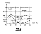
- an interpolation coefficient ⁇ 0 for the first interval ⁇ 20 for the second interval, ⁇ 40 for the third interval, ⁇ 60 for the fourth, ⁇ 80 for the fifth, ⁇ 100 for the last interval.
- Smoothing functions are also defined which are represented at figure 3 , which correspond to each of the intervals and which are such that the sum of these smoothing functions for any point of adjustment of the control means of the clutch, is equal to 1. These functions are respectively called Li (Xemb), L 2 (Xemb), L 3 (Xemb), L 4 (Xemb), L 5 (Xemb), L 6 (Xemb).
- Each smoothing function induces a weighting on the interval I x with which it is associated, as well as on the adjacent intervals I x-1 and I x + 1, and thus generates a smoothing.
- ⁇ (Xemb) ⁇ ⁇ 0 x L ⁇ 1 Xemb + ⁇ ⁇ 20 x L ⁇ 2 Xemb + .... + ⁇ ⁇ 100 x L ⁇ 6 Xemb .
- each instant t is determined in which operating interval is the clutch and the adaptation of the coefficient ⁇ i of the corresponding interval.
- the adaptations of the different interpolation coefficients are carried out interval by interval, which makes it possible, by introducing them into the formula which defines the interpolation function, to adapt this function of interpolation.
- This interpolation by segment is done only on the coefficient ⁇ which corresponds to the consideration of the heating of the clutch. Indeed, the heating phenomenon has effects depending on the operating page of the clutch.
- the use of the smoothing functions as described has the advantage of preventing this self-adaptation by segment leading to irregularities in the evolution of the constitutive law of the calculated clutch, irregular evolution that could lead to difficulties in steering the clutch. In particular, this smoothing avoids that there are non monotonies of the law of behavior of the clutch which would lead to impossibilities of inversion.
- the interpolation coefficients ⁇ 0, ⁇ 20, ⁇ 40, ⁇ 60, etc ... have varied substantially with respect to the initialization value which was equal to 0.5 , so that the weight of each of the smoothing laws has changed significantly, which leads to the smoothed interpolation function represented in FIG. figure 4 .
- the self-adaptation process takes into account two interpolations, one corresponding to the heating of the clutch, the other to wear.
- one of the interpolations is complex since it is done in segments. But we can realize simpler self-adaptations, for example by making only one interpolation and a law relating to the hot new clutch and the used clutch, and / or by not segmenting one of the interpolations.
- This method can be implemented by a control device which comprises a computer, adapted to control a coupling / decoupling device such as a clutch of a traction chain, for example a vehicle and in particular a vehicle automobile.
- a coupling / decoupling device such as a clutch of a traction chain, for example a vehicle and in particular a vehicle automobile.
Landscapes
- Engineering & Computer Science (AREA)
- General Engineering & Computer Science (AREA)
- Physics & Mathematics (AREA)
- Fluid Mechanics (AREA)
- Mechanical Engineering (AREA)
- Hydraulic Clutches, Magnetic Clutches, Fluid Clutches, And Fluid Joints (AREA)
- Arrangement And Driving Of Transmission Devices (AREA)
- Mechanical Operated Clutches (AREA)
- Paper (AREA)
- Structure Of Transmissions (AREA)
- Arrangement And Mounting Of Devices That Control Transmission Of Motive Force (AREA)
Claims (9)
- Verfahren zum Steuern einer Vorrichtung zum Kuppeln zwischen einer Eingangswelle, die von einem Motor angetrieben wird, und einer Ausgangswelle, die ein maximales Moment (Cemb) übertragen kann, das von der Position (Xemb) eines Stellantriebs der Kupplungsvorrichtung gemäß einem Verhaltensgesetz des Kupplungsmittels abhängt, das von der Zeit (Cemb = Cemb (Xemb; t)) abhängt, gemäß dem man in jedem Augenblick:- einen Sollwert (Cemb, cons) für das maximal zu übertragende Moment definiert,- die reale Position (Xemb, mes) des Stellantriebs der Kupplungsvorrichtung misst,- unter Einsatz des Sollwerts des maximal zu übertragenden Moments (Cemb, cons), der realen Messung der Position des Stellantriebs (Xemb, mes) und dem Verhaltensgesetz des Kupplungsmittels im Augenblick t (Cemb(Xemb; t)) einen Sollwert (Xemb, cons) für den Stellantrieb der Kupplungsvorrichtung bestimmt, den man an den Stellantrieb der Kupplungsvorrichtung sendet,- unter Einsatz eines Verhaltensgesetzes des Kupplungsmittels im Augenblick t, erzielt durch Interpolation zwischen einem ersten Verhaltensbezugsgesetz des Kupplungsmittels (Cemb1(Xemb)) und mindestens einem zweiten Verhaltensbezugsgesetz des Kupplungsmittels (Cemb2(Xemb), Cemb3(Xemb)), undgekennzeichnet durch
eine Selbstanpassung der Interpolation des Verhaltsgesetzes des Kupplungsmittels durch Integration der Abweichung zwischen der Schätzung in offener Schleife (Cemb, bo(t)) des maximalen Moments, das die Kupplungsvorrichtung in einem Augenblick t übertragen kann, und der Schätzung in geschlossener Schleife (Cemb, bf(t)) des Moments, das die Kupplungsvorrichtung im Augenblick t überträgt,
dadurch gekennzeichnet, dass man mindestens eine Interpolation zwischen einem ersten Bezugsgesetz (Cemb1(Xemb)) und einem zweiten Bezugsgesetz (Cemb2(Xemb)) ausführt, um durch Interpolation mit Hilfe einer Interpolationsfunktion α((Xemb;t), abhängig von der Stellung (Xemb) des Stellantriebs der Kupplungsvorrichtung, ein Zwischenverhaltensgesetz im Augenblick t (Cemb, int(xemb; t)) zu bestimmen, das man verwendet, um das Verhaltensgesetz des Kupplungsmittels zu bestimmen, und dass die Interpolationsfunktion mit einer ersten Verstärkung Kα angepasst wird,
und dass man den Schwankungsbereich der Stellung des Stellantriebs der Kupplungsvorrichtung in eine Vielzahl von Intervallen unterteilt, und dass man das Anpassen der Interpolationsfunktion intervallweise ausführt. - Verfahren nach Anspruch 1, dadurch gekennzeichnet, dass man ein Glätten der Interpolationsfunktion ausführt.
- Verfahren nach einem der Ansprüche 1 bis 2, dadurch gekennzeichnet, dass das Gesetz des Verhaltens im Augenblick t der Kupplungsvorrichtung (Cemb(Xemb;t)) gleich dem Verhaltenszwischengesetz im Augenblick t der Kupplungsvorrichtung (Cemb, int(Xemb, t)) ist;
- Verfahren nach einem der Ansprüche 1 bis 3, dadurch gekennzeichnet, dass das erste Bezugsgesetz das Verhaltensgesetz des Kupplungsmittels ist, wenn es neu und kalt ist, und dass das zweite Bezugsgesetz das Verhaltensgesetz des Kupplungsmittels ist, wenn es neu und warm ist, und dass man eine Interpolation zwischen dem Verhaltenszwischengesetz im Augenblick t und einem dritten Bezugsgesetz (Cemb3(Xemb)), das der abgenutzten Kupplungsvorrichtung entspricht, ausführt, indem man einen Interpolationskoeffizienten β verwendet, und dass man den Interpolationskoeffizenten β durch Verwenden einer zweiten Verstärkung Kβ mit gegenteiligem Vorzeichen zu dem der ersten Verstärkung Kα und im Absolutwert verglichen mit der ersten Verstärkung klein anpasst.
- Verfahren nach Anspruch 4, dadurch gekennzeichnet, dass man die Anpassung des zweiten Interpolationskoeffizienten β ununterbrochen während der ganzen Lebensdauer der Kupplungsvorrichtung anpasst, und dass man die Anpassung des ersten Kupplungskoeffizenten, eine Nutzungsperiode der Vorrichtung nach der anderen durch Neuinitialisieren zu Beginn jeder Nutzungsperiode vornimmt.
- Verfahren nach einem der Ansprüche 1 bis 5, dadurch gekennzeichnet, dass die Kupplungsvorrichtung eine gesteuerte Kupplung ist.
- Verfahren nach einem der Ansprüche 1 bis 6, dadurch gekennzeichnet, dass die Kupplungsvorrichtung in eine Zugkette und insbesondere in eine hybride Zugkette eines Kraftfahrzeugs eingebaut ist.
- Vorrichtung zum Kuppeln zwischen einer Eingangswelle und einer Ausgangwelle, wie zum Beispiel ein Kupplung, die ein Steuermittel aufweist, dadurch gekennzeichnet, dass das Steuermittel das Verfahren nach einem der Ansprüche 1 bis 6 umsetzen kann.
- Vorrichtung zum Kuppeln nach Anspruch 8, dadurch gekennzeichnet, dass sie in die Zugkette eines Kraftfahrzeugs eingebaut ist.
Applications Claiming Priority (2)
| Application Number | Priority Date | Filing Date | Title |
|---|---|---|---|
| FR0506513A FR2887606B1 (fr) | 2005-06-27 | 2005-06-27 | Procede de pilotage d'un dispositif de couplage entre un arbre d'entree et un arbre de sortie |
| PCT/FR2006/050626 WO2007000553A2 (fr) | 2005-06-27 | 2006-06-23 | Procede de pilotage d'un dispositif de couplage entre un arbre d'entree et un arbre de sortie |
Publications (2)
| Publication Number | Publication Date |
|---|---|
| EP1896747A2 EP1896747A2 (de) | 2008-03-12 |
| EP1896747B1 true EP1896747B1 (de) | 2010-05-12 |
Family
ID=35712952
Family Applications (1)
| Application Number | Title | Priority Date | Filing Date |
|---|---|---|---|
| EP06778971A Ceased EP1896747B1 (de) | 2005-06-27 | 2006-06-23 | Verfahren zur steuerung einer kopplungsvorrichtung zwischen einer eingangswelle und einer ausgangswelle |
Country Status (9)
| Country | Link |
|---|---|
| US (1) | US7908070B2 (de) |
| EP (1) | EP1896747B1 (de) |
| JP (1) | JP5142992B2 (de) |
| CN (1) | CN101213386B (de) |
| AT (1) | ATE467775T1 (de) |
| BR (1) | BRPI0613213A2 (de) |
| DE (1) | DE602006014271D1 (de) |
| FR (1) | FR2887606B1 (de) |
| WO (1) | WO2007000553A2 (de) |
Families Citing this family (8)
| Publication number | Priority date | Publication date | Assignee | Title |
|---|---|---|---|---|
| DE102007038151A1 (de) * | 2007-08-13 | 2009-02-19 | Magna Powertrain Ag & Co Kg | Verfahren zum Nachjustieren eines Aktuators einer Allradkupplung |
| FR2929672B1 (fr) * | 2008-04-04 | 2010-08-27 | Peugeot Citroen Automobiles Sa | Procede de determination automatique du point de lechage d'un embrayage par apprentissage |
| FR2929673B1 (fr) * | 2008-04-04 | 2010-08-27 | Peugeot Citroen Automobiles Sa | Procede de determination automatique du point de lechage d'un embrayage par apprentissage |
| FR2933462B1 (fr) | 2008-07-04 | 2010-07-30 | Inst Francais Du Petrole | Procede pour controler la phase de fermeture d'un embrayage d'un systeme de transmission robotisee automobile |
| IT1394918B1 (it) * | 2009-03-04 | 2012-07-27 | Ferrari Spa | Metodo di controllo per la chiusura di una frizione in una trasmissione manuale automatica |
| FR2950303B1 (fr) | 2009-09-24 | 2011-10-28 | Peugeot Citroen Automobiles Sa | Procede d'apprentisage du point de lechage d'un embrayage par la courbe caracteristique de l'embrayage pour un vehicule hybride |
| FR2954441B1 (fr) * | 2009-12-17 | 2012-03-09 | Peugeot Citroen Automobiles Sa | Procede et systeme d'accouplement d'une machine electrique sur un train roulant de vehicule, notamment d'un vehicule automobile hybride |
| FR3010473B1 (fr) * | 2013-09-12 | 2015-08-21 | Valeo Embrayages | Procede et systeme de pilotage d'un embrayage |
Family Cites Families (14)
| Publication number | Priority date | Publication date | Assignee | Title |
|---|---|---|---|---|
| US5119695A (en) * | 1991-06-27 | 1992-06-09 | Saturn Corporation | Open-loop clutch-to-clutch upshift control having clutch overlap regulation |
| NO314174B1 (no) * | 1995-12-18 | 2003-02-10 | Luk Getriebe Systeme Gmbh | Motorkjöretöy |
| JP3901852B2 (ja) * | 1998-07-22 | 2007-04-04 | 日野自動車株式会社 | クラッチ制御装置 |
| JP4501268B2 (ja) * | 2000-10-18 | 2010-07-14 | いすゞ自動車株式会社 | 車両用駆動装置の摩擦クラッチ制御装置 |
| WO2002059493A1 (de) * | 2001-01-24 | 2002-08-01 | Luk Lamellen Und Kupplungsbau Beteiligungs Kg | Verfahren zur anpassung der kupplungskennlinie einer automatisie rten kupplung eines fahrzeuges |
| JP4050002B2 (ja) * | 2001-02-28 | 2008-02-20 | ジヤトコ株式会社 | パラレルハイブリッド車両 |
| AU2002311074A1 (en) * | 2001-04-02 | 2002-10-15 | Luk Lamellen Und Kupplungsbau Beteiligungs Kg | Method for controlling an automatic clutch |
| JP4093050B2 (ja) * | 2002-12-19 | 2008-05-28 | トヨタ自動車株式会社 | 自動クラッチシステムの制御装置 |
| EP1437520A3 (de) * | 2003-01-13 | 2009-09-02 | Continental Automotive GmbH | Verfahren zum Steuern einer automatisch betätigten Kupplung |
| US7121390B2 (en) * | 2003-02-20 | 2006-10-17 | Luk Lamellen Und Kupplungsbau Beteiligungs Kg | Method and apparatus for adapting a clutch torque |
| FR2859258B1 (fr) * | 2003-08-29 | 2006-02-24 | Renault Sa | Procede pour selectioner une loi de commande du systeme de pilotage d'un embrayage en determinant trois points de fonctionnement |
| US7010406B2 (en) * | 2004-02-14 | 2006-03-07 | General Motors Corporation | Shift inhibit control for multi-mode hybrid drive |
| FR2887495B1 (fr) * | 2005-06-27 | 2007-09-28 | Peugeot Citroen Automobiles Sa | Procede pour piloter le couplage et le decouplage du premier moteur et du deuxieme moteur d'un groupe motopropulseur hybride parallele |
| US20070294017A1 (en) * | 2006-06-20 | 2007-12-20 | Eaton Corporation | Method for estimating clutch engagement parameters in a strategy for clutch management in a vehicle powertrain |
-
2005
- 2005-06-27 FR FR0506513A patent/FR2887606B1/fr not_active Expired - Fee Related
-
2006
- 2006-06-23 JP JP2008517565A patent/JP5142992B2/ja not_active Expired - Fee Related
- 2006-06-23 US US11/993,853 patent/US7908070B2/en not_active Expired - Fee Related
- 2006-06-23 AT AT06778971T patent/ATE467775T1/de not_active IP Right Cessation
- 2006-06-23 CN CN2006800199964A patent/CN101213386B/zh not_active Expired - Fee Related
- 2006-06-23 DE DE602006014271T patent/DE602006014271D1/de active Active
- 2006-06-23 EP EP06778971A patent/EP1896747B1/de not_active Ceased
- 2006-06-23 WO PCT/FR2006/050626 patent/WO2007000553A2/fr not_active Ceased
- 2006-06-23 BR BRPI0613213-8A patent/BRPI0613213A2/pt not_active Application Discontinuation
Also Published As
| Publication number | Publication date |
|---|---|
| FR2887606A1 (fr) | 2006-12-29 |
| US7908070B2 (en) | 2011-03-15 |
| JP5142992B2 (ja) | 2013-02-13 |
| CN101213386B (zh) | 2010-05-19 |
| DE602006014271D1 (de) | 2010-06-24 |
| WO2007000553A3 (fr) | 2007-05-03 |
| US20100161189A1 (en) | 2010-06-24 |
| JP2008544189A (ja) | 2008-12-04 |
| FR2887606B1 (fr) | 2008-09-12 |
| EP1896747A2 (de) | 2008-03-12 |
| WO2007000553A2 (fr) | 2007-01-04 |
| CN101213386A (zh) | 2008-07-02 |
| ATE467775T1 (de) | 2010-05-15 |
| BRPI0613213A2 (pt) | 2012-10-09 |
Similar Documents
| Publication | Publication Date | Title |
|---|---|---|
| EP1896747A2 (de) | Verfahren zur steuerung einer kopplungsvorrichtung zwischen einer eingangswelle und einer ausgangswelle | |
| EP3593005B1 (de) | Verfahren zur steuerung einer an eine elektrische maschine beim start eines verbrennungsmotors angeschlossenen kupplung | |
| WO2015036718A1 (fr) | Determination d'un couple dans une chaine de transmission de vehicule automobile | |
| CA2827403C (fr) | Procede de calibration d'un couplemetre a torsion | |
| EP2297476B1 (de) | Modul zur drehmomentsteuerung einer reibkupplungsvorrichtung eines kraftfahrzeugantriebsstrangs mit zustandsbeobachter | |
| EP1510717B1 (de) | Auswahlverfahren für Verhältnis einer Kupplungssteuerung mittels drei Fonctionspunkten | |
| EP1651880B1 (de) | Adaptives kupplungssteuerungssystem eines fahrzeugsantriebsstrangs | |
| FR3008916A1 (fr) | Procede de commande d'un segment de bras de comanipulateur | |
| FR2920848A1 (fr) | Procede et dispositif de commande d'un embrayage par determination du couple transmis pour un vehicule automobile. | |
| EP2926019B1 (de) | Verfahren und vorrichtung zur anpassung der nominalen eigenschaft eines von einer kupplung als funktion geschätzter drehmomentunterschiede übertragenen drehmoments | |
| EP4272038B1 (de) | Verfahren zur steuerung einer betätigungsanordnung | |
| FR3109337A1 (fr) | Procede de pilotage du couple produit sur l’arbre primaire d’un groupe motopropulseur de vehicule automobile hybride | |
| EP2354599A1 (de) | System und Verfahren zum Steuern eines automatischen Getriebes | |
| EP3040228B1 (de) | Kraftfahrzeug mit hydraulischer übertragung des motordrehmoments | |
| EP4028677B1 (de) | Verfahren und vorrichtung zur bestimmung des von einer kupplung übertragenen drehmoments | |
| FR2919697A1 (fr) | Procede de commande d'un groupe moto propulseur de vehicule. | |
| EP1429011A1 (de) | Verfahren und System zur Steuerung des Drehmoments eines Verbrennungsmotors für ein Automobil | |
| JP5016640B2 (ja) | 駆動装置および速度指令生成装置 | |
| WO2006027527A1 (fr) | Procede de commande d'un systeme de transmission de couple de vehicule automobile et systeme de commande correspondant | |
| FR2947768A1 (fr) | Gestion du couple d’un actionneur de vehicule automobile a quatre roues motrices | |
| FR2797928A1 (fr) | Procede pour determiner le couple transmis par un embrayage a friction d'une boite de vitesses commandee en charge, couplee a un moteur d'entrainement | |
| FR2921525A1 (fr) | Dispositif d'asservissement en couple d'une machine electrique d'une chaine de traction electrique d'un vehicule comportant un estimateur de couple parasite | |
| FR3148354A1 (fr) | Procédé de régulation du régime d’un rotor d’une faucheuse débroussailleuse au moins en fonction de la charge, et dispositif pour la mise en œuvre du procédé | |
| EP2806187A1 (de) | Verbrennungsmotor eines Kraftfahrzeugs mit adaptivem Riemenspanner | |
| FR3103440A1 (fr) | Procede de determination du couple transmis par le moteur a la chaine de traction |
Legal Events
| Date | Code | Title | Description |
|---|---|---|---|
| PUAI | Public reference made under article 153(3) epc to a published international application that has entered the european phase |
Free format text: ORIGINAL CODE: 0009012 |
|
| 17P | Request for examination filed |
Effective date: 20071107 |
|
| AK | Designated contracting states |
Kind code of ref document: A2 Designated state(s): AT BE BG CH CY CZ DE DK EE ES FI FR GB GR HU IE IS IT LI LT LU LV MC NL PL PT RO SE SI SK TR |
|
| DAX | Request for extension of the european patent (deleted) | ||
| 17Q | First examination report despatched |
Effective date: 20080411 |
|
| DAX | Request for extension of the european patent (deleted) | ||
| GRAP | Despatch of communication of intention to grant a patent |
Free format text: ORIGINAL CODE: EPIDOSNIGR1 |
|
| GRAS | Grant fee paid |
Free format text: ORIGINAL CODE: EPIDOSNIGR3 |
|
| GRAA | (expected) grant |
Free format text: ORIGINAL CODE: 0009210 |
|
| AK | Designated contracting states |
Kind code of ref document: B1 Designated state(s): AT BE BG CH CY CZ DE DK EE ES FI FR GB GR HU IE IS IT LI LT LU LV MC NL PL PT RO SE SI SK TR |
|
| REG | Reference to a national code |
Ref country code: GB Ref legal event code: FG4D Free format text: NOT ENGLISH |
|
| REG | Reference to a national code |
Ref country code: CH Ref legal event code: EP |
|
| REG | Reference to a national code |
Ref country code: IE Ref legal event code: FG4D Free format text: LANGUAGE OF EP DOCUMENT: FRENCH |
|
| REF | Corresponds to: |
Ref document number: 602006014271 Country of ref document: DE Date of ref document: 20100624 Kind code of ref document: P |
|
| REG | Reference to a national code |
Ref country code: NL Ref legal event code: VDEP Effective date: 20100512 |
|
| LTIE | Lt: invalidation of european patent or patent extension |
Effective date: 20100512 |
|
| REG | Reference to a national code |
Ref country code: GB Ref legal event code: 746 Effective date: 20101006 |
|
| PG25 | Lapsed in a contracting state [announced via postgrant information from national office to epo] |
Ref country code: SE Free format text: LAPSE BECAUSE OF FAILURE TO SUBMIT A TRANSLATION OF THE DESCRIPTION OR TO PAY THE FEE WITHIN THE PRESCRIBED TIME-LIMIT Effective date: 20100512 Ref country code: NL Free format text: LAPSE BECAUSE OF FAILURE TO SUBMIT A TRANSLATION OF THE DESCRIPTION OR TO PAY THE FEE WITHIN THE PRESCRIBED TIME-LIMIT Effective date: 20100512 Ref country code: LT Free format text: LAPSE BECAUSE OF FAILURE TO SUBMIT A TRANSLATION OF THE DESCRIPTION OR TO PAY THE FEE WITHIN THE PRESCRIBED TIME-LIMIT Effective date: 20100512 Ref country code: ES Free format text: LAPSE BECAUSE OF FAILURE TO SUBMIT A TRANSLATION OF THE DESCRIPTION OR TO PAY THE FEE WITHIN THE PRESCRIBED TIME-LIMIT Effective date: 20100823 |
|
| PG25 | Lapsed in a contracting state [announced via postgrant information from national office to epo] |
Ref country code: AT Free format text: LAPSE BECAUSE OF FAILURE TO SUBMIT A TRANSLATION OF THE DESCRIPTION OR TO PAY THE FEE WITHIN THE PRESCRIBED TIME-LIMIT Effective date: 20100512 Ref country code: FI Free format text: LAPSE BECAUSE OF FAILURE TO SUBMIT A TRANSLATION OF THE DESCRIPTION OR TO PAY THE FEE WITHIN THE PRESCRIBED TIME-LIMIT Effective date: 20100512 Ref country code: IS Free format text: LAPSE BECAUSE OF FAILURE TO SUBMIT A TRANSLATION OF THE DESCRIPTION OR TO PAY THE FEE WITHIN THE PRESCRIBED TIME-LIMIT Effective date: 20100912 Ref country code: LV Free format text: LAPSE BECAUSE OF FAILURE TO SUBMIT A TRANSLATION OF THE DESCRIPTION OR TO PAY THE FEE WITHIN THE PRESCRIBED TIME-LIMIT Effective date: 20100512 Ref country code: SI Free format text: LAPSE BECAUSE OF FAILURE TO SUBMIT A TRANSLATION OF THE DESCRIPTION OR TO PAY THE FEE WITHIN THE PRESCRIBED TIME-LIMIT Effective date: 20100512 |
|
| REG | Reference to a national code |
Ref country code: IE Ref legal event code: FD4D |
|
| BERE | Be: lapsed |
Owner name: PEUGEOT CITROEN AUTOMOBILES S.A. Effective date: 20100630 |
|
| PG25 | Lapsed in a contracting state [announced via postgrant information from national office to epo] |
Ref country code: GR Free format text: LAPSE BECAUSE OF FAILURE TO SUBMIT A TRANSLATION OF THE DESCRIPTION OR TO PAY THE FEE WITHIN THE PRESCRIBED TIME-LIMIT Effective date: 20100813 Ref country code: CY Free format text: LAPSE BECAUSE OF FAILURE TO SUBMIT A TRANSLATION OF THE DESCRIPTION OR TO PAY THE FEE WITHIN THE PRESCRIBED TIME-LIMIT Effective date: 20100526 Ref country code: PL Free format text: LAPSE BECAUSE OF FAILURE TO SUBMIT A TRANSLATION OF THE DESCRIPTION OR TO PAY THE FEE WITHIN THE PRESCRIBED TIME-LIMIT Effective date: 20100512 |
|
| PG25 | Lapsed in a contracting state [announced via postgrant information from national office to epo] |
Ref country code: MC Free format text: LAPSE BECAUSE OF NON-PAYMENT OF DUE FEES Effective date: 20100630 Ref country code: IE Free format text: LAPSE BECAUSE OF FAILURE TO SUBMIT A TRANSLATION OF THE DESCRIPTION OR TO PAY THE FEE WITHIN THE PRESCRIBED TIME-LIMIT Effective date: 20100512 Ref country code: DK Free format text: LAPSE BECAUSE OF FAILURE TO SUBMIT A TRANSLATION OF THE DESCRIPTION OR TO PAY THE FEE WITHIN THE PRESCRIBED TIME-LIMIT Effective date: 20100512 Ref country code: EE Free format text: LAPSE BECAUSE OF FAILURE TO SUBMIT A TRANSLATION OF THE DESCRIPTION OR TO PAY THE FEE WITHIN THE PRESCRIBED TIME-LIMIT Effective date: 20100512 Ref country code: PT Free format text: LAPSE BECAUSE OF FAILURE TO SUBMIT A TRANSLATION OF THE DESCRIPTION OR TO PAY THE FEE WITHIN THE PRESCRIBED TIME-LIMIT Effective date: 20100913 |
|
| REG | Reference to a national code |
Ref country code: CH Ref legal event code: PL |
|
| PG25 | Lapsed in a contracting state [announced via postgrant information from national office to epo] |
Ref country code: CZ Free format text: LAPSE BECAUSE OF FAILURE TO SUBMIT A TRANSLATION OF THE DESCRIPTION OR TO PAY THE FEE WITHIN THE PRESCRIBED TIME-LIMIT Effective date: 20100512 Ref country code: RO Free format text: LAPSE BECAUSE OF FAILURE TO SUBMIT A TRANSLATION OF THE DESCRIPTION OR TO PAY THE FEE WITHIN THE PRESCRIBED TIME-LIMIT Effective date: 20100512 Ref country code: SK Free format text: LAPSE BECAUSE OF FAILURE TO SUBMIT A TRANSLATION OF THE DESCRIPTION OR TO PAY THE FEE WITHIN THE PRESCRIBED TIME-LIMIT Effective date: 20100512 |
|
| PLBE | No opposition filed within time limit |
Free format text: ORIGINAL CODE: 0009261 |
|
| STAA | Information on the status of an ep patent application or granted ep patent |
Free format text: STATUS: NO OPPOSITION FILED WITHIN TIME LIMIT |
|
| PG25 | Lapsed in a contracting state [announced via postgrant information from national office to epo] |
Ref country code: IT Free format text: LAPSE BECAUSE OF FAILURE TO SUBMIT A TRANSLATION OF THE DESCRIPTION OR TO PAY THE FEE WITHIN THE PRESCRIBED TIME-LIMIT Effective date: 20100512 |
|
| 26N | No opposition filed |
Effective date: 20110215 |
|
| PG25 | Lapsed in a contracting state [announced via postgrant information from national office to epo] |
Ref country code: CH Free format text: LAPSE BECAUSE OF NON-PAYMENT OF DUE FEES Effective date: 20100630 Ref country code: LI Free format text: LAPSE BECAUSE OF NON-PAYMENT OF DUE FEES Effective date: 20100630 |
|
| REG | Reference to a national code |
Ref country code: DE Ref legal event code: R097 Ref document number: 602006014271 Country of ref document: DE Effective date: 20110214 |
|
| PG25 | Lapsed in a contracting state [announced via postgrant information from national office to epo] |
Ref country code: BE Free format text: LAPSE BECAUSE OF NON-PAYMENT OF DUE FEES Effective date: 20100630 |
|
| PG25 | Lapsed in a contracting state [announced via postgrant information from national office to epo] |
Ref country code: HU Free format text: LAPSE BECAUSE OF FAILURE TO SUBMIT A TRANSLATION OF THE DESCRIPTION OR TO PAY THE FEE WITHIN THE PRESCRIBED TIME-LIMIT Effective date: 20101113 Ref country code: BG Free format text: LAPSE BECAUSE OF FAILURE TO SUBMIT A TRANSLATION OF THE DESCRIPTION OR TO PAY THE FEE WITHIN THE PRESCRIBED TIME-LIMIT Effective date: 20100512 Ref country code: LU Free format text: LAPSE BECAUSE OF NON-PAYMENT OF DUE FEES Effective date: 20100623 |
|
| PG25 | Lapsed in a contracting state [announced via postgrant information from national office to epo] |
Ref country code: TR Free format text: LAPSE BECAUSE OF FAILURE TO SUBMIT A TRANSLATION OF THE DESCRIPTION OR TO PAY THE FEE WITHIN THE PRESCRIBED TIME-LIMIT Effective date: 20100512 |
|
| PG25 | Lapsed in a contracting state [announced via postgrant information from national office to epo] |
Ref country code: BG Free format text: LAPSE BECAUSE OF FAILURE TO SUBMIT A TRANSLATION OF THE DESCRIPTION OR TO PAY THE FEE WITHIN THE PRESCRIBED TIME-LIMIT Effective date: 20100812 |
|
| REG | Reference to a national code |
Ref country code: FR Ref legal event code: PLFP Year of fee payment: 11 |
|
| REG | Reference to a national code |
Ref country code: FR Ref legal event code: PLFP Year of fee payment: 12 |
|
| PGFP | Annual fee paid to national office [announced via postgrant information from national office to epo] |
Ref country code: FR Payment date: 20170523 Year of fee payment: 12 Ref country code: DE Payment date: 20170522 Year of fee payment: 12 Ref country code: GB Payment date: 20170526 Year of fee payment: 12 |
|
| REG | Reference to a national code |
Ref country code: FR Ref legal event code: CA Effective date: 20180312 Ref country code: FR Ref legal event code: CD Owner name: PEUGEOT CITROEN AUTOMOBILES SA, FR Effective date: 20180312 |
|
| REG | Reference to a national code |
Ref country code: DE Ref legal event code: R119 Ref document number: 602006014271 Country of ref document: DE |
|
| GBPC | Gb: european patent ceased through non-payment of renewal fee |
Effective date: 20180623 |
|
| PG25 | Lapsed in a contracting state [announced via postgrant information from national office to epo] |
Ref country code: GB Free format text: LAPSE BECAUSE OF NON-PAYMENT OF DUE FEES Effective date: 20180623 Ref country code: DE Free format text: LAPSE BECAUSE OF NON-PAYMENT OF DUE FEES Effective date: 20190101 Ref country code: FR Free format text: LAPSE BECAUSE OF NON-PAYMENT OF DUE FEES Effective date: 20180630 |