EP1896816B1 - Vorrichtung zur bestimmung des klopfzustands - Google Patents
Vorrichtung zur bestimmung des klopfzustands Download PDFInfo
- Publication number
- EP1896816B1 EP1896816B1 EP06767568.6A EP06767568A EP1896816B1 EP 1896816 B1 EP1896816 B1 EP 1896816B1 EP 06767568 A EP06767568 A EP 06767568A EP 1896816 B1 EP1896816 B1 EP 1896816B1
- Authority
- EP
- European Patent Office
- Prior art keywords
- value
- intensity
- knock
- determination level
- knocking
- Prior art date
- Legal status (The legal status is an assumption and is not a legal conclusion. Google has not performed a legal analysis and makes no representation as to the accuracy of the status listed.)
- Not-in-force
Links
- 238000002485 combustion reaction Methods 0.000 claims description 73
- 238000003860 storage Methods 0.000 claims description 5
- 238000009826 distribution Methods 0.000 description 35
- 230000006399 behavior Effects 0.000 description 8
- 238000001514 detection method Methods 0.000 description 8
- 230000001186 cumulative effect Effects 0.000 description 7
- 238000000034 method Methods 0.000 description 6
- 238000010606 normalization Methods 0.000 description 5
- 230000001276 controlling effect Effects 0.000 description 4
- 239000000446 fuel Substances 0.000 description 4
- 230000007423 decrease Effects 0.000 description 3
- 239000000203 mixture Substances 0.000 description 3
- XLYOFNOQVPJJNP-UHFFFAOYSA-N water Substances O XLYOFNOQVPJJNP-UHFFFAOYSA-N 0.000 description 3
- 230000009467 reduction Effects 0.000 description 2
- 230000000979 retarding effect Effects 0.000 description 2
- 230000007704 transition Effects 0.000 description 2
- 239000003054 catalyst Substances 0.000 description 1
- 238000006243 chemical reaction Methods 0.000 description 1
- 239000000498 cooling water Substances 0.000 description 1
- 230000001419 dependent effect Effects 0.000 description 1
- 230000006866 deterioration Effects 0.000 description 1
- 238000011161 development Methods 0.000 description 1
- 230000018109 developmental process Effects 0.000 description 1
- 238000010586 diagram Methods 0.000 description 1
- 230000004907 flux Effects 0.000 description 1
- 230000006870 function Effects 0.000 description 1
- 230000010354 integration Effects 0.000 description 1
- 238000004519 manufacturing process Methods 0.000 description 1
- 230000001105 regulatory effect Effects 0.000 description 1
- 230000000630 rising effect Effects 0.000 description 1
- 238000004088 simulation Methods 0.000 description 1
- 230000002123 temporal effect Effects 0.000 description 1
Images


Classifications
-
- G—PHYSICS
- G01—MEASURING; TESTING
- G01L—MEASURING FORCE, STRESS, TORQUE, WORK, MECHANICAL POWER, MECHANICAL EFFICIENCY, OR FLUID PRESSURE
- G01L23/00—Devices or apparatus for measuring or indicating or recording rapid changes, such as oscillations, in the pressure of steam, gas, or liquid; Indicators for determining work or energy of steam, internal-combustion, or other fluid-pressure engines from the condition of the working fluid
- G01L23/22—Devices or apparatus for measuring or indicating or recording rapid changes, such as oscillations, in the pressure of steam, gas, or liquid; Indicators for determining work or energy of steam, internal-combustion, or other fluid-pressure engines from the condition of the working fluid for detecting or indicating knocks in internal-combustion engines; Units comprising pressure-sensitive members combined with ignitors for firing internal-combustion engines
- G01L23/221—Devices or apparatus for measuring or indicating or recording rapid changes, such as oscillations, in the pressure of steam, gas, or liquid; Indicators for determining work or energy of steam, internal-combustion, or other fluid-pressure engines from the condition of the working fluid for detecting or indicating knocks in internal-combustion engines; Units comprising pressure-sensitive members combined with ignitors for firing internal-combustion engines for detecting or indicating knocks in internal combustion engines
- G01L23/225—Devices or apparatus for measuring or indicating or recording rapid changes, such as oscillations, in the pressure of steam, gas, or liquid; Indicators for determining work or energy of steam, internal-combustion, or other fluid-pressure engines from the condition of the working fluid for detecting or indicating knocks in internal-combustion engines; Units comprising pressure-sensitive members combined with ignitors for firing internal-combustion engines for detecting or indicating knocks in internal combustion engines circuit arrangements therefor
Definitions
- the present invention relates to a technique for determining a knocking state by knocking state determination device, and in particular, relates to a technique in which intensity values relating to the intensity of vibration of an internal combustion engine are detected, and based on the intensity values larger than a desired value, a knocking state is determined.
- a knock determination level is set by multiplying an average value of knock sensor signals with a constant K.
- KCS Kernel Control System
- knock intensity values V those higher than knock determination level VKD are determined as knock intensity values V caused by knocking. That is, the number (frequency) of knock intensity values higher than knock determination level VKD are determined as the number of times (frequency) that knocking has occurred.
- the prior art document US 5 215 058 A discloses a knock control apparatus for internal combustion engines which comprises a unit for calculating a mean value of the knock intensity value, a unit for calculating a mean deviation between the knock intensity value and the mean value and a knock decision level calculating unit for calculating a knock decision level. Based on a comparison between the knock intensity value and the knock decision level knock control factors are controlled.
- a knocking state determination device determines a state of knocking in an internal combustion engine.
- This knocking state determination device includes: a detector for detecting a plurality of intensity values relating to the intensity of vibration caused in the internal combustion engine; a calculator for calculating a second value based on intensity values not more than a first value, among the plurality of intensity values; a corrector for correcting the first value such that a deviation between the first value and the second value becomes smaller than a predetermined deviation when the deviation between the first value and the second value is larger than the predetermined deviation; and a determiner for determining a knocking occurrence state based on intensity values larger than at least one of the corrected first value and a second value calculated based on intensity values not more than the corrected first value.
- the detector detects a plurality of intensity values relating to the intensity of vibration caused in the internal combustion engine. Based on intensity values not more than the first value among the plurality of intensity values, the calculator calculates the second value. For example, the median of the intensity values not more than the first value and the standard deviation value from the minimum value of the intensity values to the intensity values not more than the first value are calculated. By adding a product of a predetermined coefficient and the standard deviation value to the median, the second value is calculated. When the deviation between the second value calculated in this way and the first value is larger than a predetermined deviation, the first value is corrected such that the deviation between the first value and the second value becomes smaller than the predetermined deviation.
- the first value is, for example, decremented.
- the second value is also decremented corresponding to the correction of the first value.
- the determiner determines a knocking occurrence state based on intensity values larger than at least one value of the corrected first value and the second value calculated based on the intensity values not more than the corrected first value. For example, the number of intensity values larger than at least one value of the corrected first value and the second value calculated based on the intensity values not more than the corrected first value is determined as the number of times that knocking has occurred. Thereby, it is possible to determine a knocking occurrence state by using at least one of the second value smaller than the case of calculating the second value based on all of the plurality of intensity values and the first value having a smaller deviation with the second value, as a threshold.
- the determiner includes a number determiner which determines the number of intensity values larger than at least one value of the corrected first value and the second value calculated based on the intensity values not more than the corrected first value, as the number of times that knocking has occurred.
- the number of intensity values larger than at least one of the corrected first value and the second value calculated based on the intensity values not more than the corrected first value is determined as the number of times that knocking has occurred. Therefore, in the case where a large number of large intensity values are detected, it is possible to prevent the number of times that knocking has occurred from becoming smaller than the actual number of occurrences due to a threshold for determining presence or absence of knocking becoming high. Consequently, it is possible to determine a knocking occurrence state with high accuracy.
- the knocking state determination device further includes: a median calculator for calculating the median of intensity values not more than the first value; and a standard deviation value calculator for calculating the standard deviation value from the minimum value of the intensity values to the intensity values not more than the first value.
- the calculator calculates the second value by adding a product of a predetermined coefficient and the standard deviation value to the median.
- the second value is calculated by adding a product of the standard deviation from the minimum value of the intensity values to the intensity values not more than the first value and a coefficient, to the median. Therefore, it is possible to calculate the second value to be used for determining a knocking occurrence state.
- the corrector corrects the first value to be decremented.
- the corrector decrements the first value.
- the second value is calculated from frequency distribution of intensity values, so when the first value is decremented so that the intensity values used for calculating the second value are decremented, the second value is decremented.
- a threshold which is to be used for determining presence or absence of knocking. Therefore, it is possible to prevent the detected number of times that knocking has occurred from becoming smaller than the actual number of occurrences due to a threshold for determining presence or absence of knocking becoming high.
- the knocking state determination device further includes an intensity detector for detecting the intensity of vibration caused by combustion of the internal combustion engine.
- the intensity value is a value that a peak value of the intensity of vibration of the internal combustion engine in a predetermined crank angle is logarithmically converted.
- a value that a peak value of the intensity of vibration is logarithmically converted is used as an intensity value.
- the knocking state determination device further includes: an intensity detector for detecting the intensity of vibration caused by combustion of the internal combustion engine; a storage for previously storing a waveform of vibration of the internal combustion engine in a predetermined crank angle; a waveform detector for detecting a waveform of vibration of the internal combustion engine in a predetermined crank angle; and a deviation calculator for calculating a value relating to a deviation between a stored waveform and a detected waveform, based on the result of comparing the stored waveform with the detected waveform.
- An intensity value is a value that a product of a peak value of the intensity of vibration of the internal combustion engine in a predetermined crank angle and a value relating to the deviation is logarithmically converted.
- a waveform of vibration of the internal combustion engine is detected.
- This waveform is, for example, compared with a waveform previously stored as a waveform when knocking occurs.
- a value relating to the deviation between the detected waveform and the stored waveform is calculated.
- an intensity value a value that a product of a peak value of the intensity and a value relating to the deviation is logarithmically converted is used.
- an intensity value considering a waveform (behavior) of vibration in addition to the magnitude of vibration. Therefore, the detected intensity of vibration can be analyzed multilaterally.
- the knocking state determination device further includes an intensity detector for detecting the intensity of vibration of an in-cylinder pressure of the internal combustion engine.
- An intensity value is a value that a peak value of the intensity of vibration of the in-cylinder pressure in a predetermined crank angle is logarithmically converted.
- a value that a peak value of the intensity of vibration of the in-cylinder pressure is logarithmically converted is used as an intensity value.
- a knocking state determination device determines a knocking state in an internal combustion engine.
- This knocking state determination device includes: a detector for detecting a plurality of intensity values relating to the intensity of vibration caused in the internal combustion engine; a calculator for calculating a second value based on intensity values not more than a first value, among the plurality of intensity values; a corrector for correcting the first value such that the first value becomes not less than the second value when the first value is smaller than the second value, and the first value becomes not more than the second value when the first value is larger than the second value; and a determiner for determining a knocking occurrence state based on intensity values larger than at least one of the corrected first value and a second value calculated based on the intensity values not more than the corrected first value.
- the detector detects a plurality of intensity values relating to the intensity of vibration caused in the internal combustion engine. Based on intensity values not more than a first value among the plurality of intensity values, the calculator calculates a second value. For example, the median of the intensity values not more than the first value and the standard deviation value from the minimum value of the intensity values to the intensity values not more than the first value are calculated. By adding a product of a predetermined coefficient and the standard deviation value to the median, the second value is calculated. By comparing the second value calculated in this way with the first value, the first value is corrected such that the first value becomes not less than the second value when the first value is smaller than the second value, and the first value becomes not more than the second value when the first value is larger than the second value.
- the first value is, for example, decremented.
- the second value is decremented corresponding to the correction of the first value.
- the determiner determines a knocking occurrence state based on intensity values larger than at least one value of the corrected first value and the second value calculated based on the intensity values not more than the corrected first value. For example, the number of intensity values larger than at least one value of the corrected first value and the second value calculated based on the intensity values not more than the corrected first value is determined as the number of times that knocking has occurred.
- the determiner includes a number determiner which determines the number of intensity values larger than at least one value of the corrected first value and the second value calculated based on the intensity values not more than the corrected first value, as the number of times that knocking has occurred.
- the number of intensity values larger than at least one of the corrected first value and the second value calculated based on the intensity values not more than the corrected first value is determined as the number of times that knocking has occurred.
- the knocking state determination device further includes: a median calculator for calculating the median of intensity values not more than the first value; and a standard deviation value calculator for calculating the standard deviation value from the minimum value of the intensity values to intensity values not more than the first value.
- the calculator calculates the second value by adding a product of a predetermined coefficient and the standard deviation value to the median.
- the second value is calculated by adding a product of the standard deviation from the minimum value of the intensity values to the intensity values not more than the first value and a coefficient, to the median.
- the corrector corrects the first value to be decremented.
- the corrector decrements the first value.
- the second value is calculated from frequency distribution of intensity values, so when the first value is decremented so that the intensity values used for calculating the second value are decremented, the second value is decremented.
- the threshold which is to be used for determining presence or absence of knocking. Therefore, so it is possible to prevent the number of times that knocking is determined to have occurred from becoming smaller than the actual number of occurrences due to the threshold for determining presence or absence of knocking becoming high.
- the knocking state determination device further includes an intensity detector for detecting the intensity of vibration caused by combustion of the internal combustion engine.
- An intensity value is a value that a peak value of the intensity of vibration of the internal combustion engine in a predetermined crank angle is logarithmically converted.
- a value that a peak value of the intensity of vibration is logarithmically converted is used as an intensity value.
- the knocking state determination device further includes: an intensity detector for detecting the intensity of vibration caused by combustion of the internal combustion engine; a storage for previously storing a waveform of vibration of the internal combustion engine in a predetermined crank angle; a waveform detector for detecting a waveform of vibration of the internal combustion engine in a predetermined crank angle; and a deviation calculator for calculating a value relating to the deviation between a stored waveform and a detected waveform, based on the result of comparing the stored waveform with the detected waveform.
- An intensity value is a value in which a product of a peak value of the intensity of vibration of the internal combustion engine in a predetermined crank angle and a value relating to the deviation is logarithmically converted.
- a waveform of vibration of the internal combustion engine is detected.
- This waveform is, for example, compared with a waveform previously stored as a waveform when knocking occurs.
- a value relating to the deviation between the detected waveform and the stored waveform is calculated.
- an intensity value a value that a product of a peak value of the intensity and a value relating to the deviation is used.
- an intensity value considering a waveform (behavior) of vibration in addition to the magnitude of vibration. Therefore, the detected intensity of vibration can be analyzed multilaterally.
- the knocking state determination device further includes an intensity detector for detecting the intensity of vibration of an in-cylinder pressure of the internal combustion engine.
- An intensity value is a value that a peak value of the intensity of vibration of the in-cylinder pressure in a predetermined crank angle is logarithmically converted.
- a value that a peak value of the intensity of vibration of the in-cylinder pressure is logarithmically converted is used as an intensity value.
- a knocking state determination device determines a knocking state in an internal combustion engine.
- This knocking state determination device includes: a detector for detecting a plurality of intensity values relating to the intensity of vibration caused in the internal combustion engine; a calculator for calculating a knock determination level by calculating the standard deviation value and the median of at least a part of the plurality of intensity values, and adding a product of a predetermined coefficient and the standard deviation to the median; a remover for repeatedly removing maximum values from the intensity values used for calculating the knock determination level such that a deviation between the maximum value of the intensity values used for calculating the knock determination level and the knock determination level becomes smaller when the deviation between the maximum value of the intensity values used for calculating the knock determination level and the knock determination level is larger than a predetermined deviation, whereby reducing the intensity values used for calculating the knock determination level; and a determiner for determining a knocking occurrence state based on intensity values larger than at least one of the maximum value of the intensity values used for calculating the knock
- the detector detects a plurality of intensity values relating to the intensity of vibration caused in the internal combustion engine. Then, the standard deviation value and the median of at least a part of the plurality of intensity values are calculated, and a product of a predetermined coefficient and the standard deviation value is added to the median, whereby a knock determination level is calculated.
- a knock determination level is calculated.
- the determiner determines a knocking occurrence state based on intensity values larger than at least one value of the maximum value of selected intensity values and the knock determination level. For example, it is determined that the number of intensity values larger than at least one value of the maximum value of the selected intensity values and the knock determination level as the number of times that knocking has occurred. Thereby, it is possible to determine a knocking occurrence state by using at least one of a knock determination level smaller than the case of calculating a knock determination level based on all of the plurality of intensity values and a maximum value having a smaller deviation with the knock determination level, as a threshold.
- the knocking state determination device is, the determiner includes a number determiner which determines the number of intensity values larger than at least one value of the maximum value in the intensity values used for calculating the knock determination level and the knock determination level as the number of times that knocking is determined to have occurred.
- the number of intensity values larger than at least one value of the maximum value of the intensity values used for calculating the knock determination level and the knock determination level is determined as the number of times that knocking has occurred.
- the knocking state determination device further includes an intensity detector for detecting the intensity of vibration caused by combustion of the internal combustion engine.
- An intensity value is a value in which a peak value of the intensity of vibration of the internal combustion engine in a predetermined crank angle is logarithmically converted.
- an intensity value a value in which a peak value of the intensity of vibration is logarithmically converted.
- the knocking state determination device further includes: an intensity detector for detecting the intensity of vibration caused by combustion of the internal combustion engine; a storage for previously storing a waveform of vibration of the internal combustion engine in a predetermined crank angle; a waveform detector for detecting a waveform of vibration of the internal combustion engine in a predetermined crank angle; and a deviation calculator for calculating a value relating to the deviation between a stored waveform and a detected waveform, based on the result of comparing the stored waveform with the detected waveform.
- the intensity value is a value that a product of a peak value of the intensity of vibration of the internal combustion engine in a predetermined crank angle and a value relating to the deviation is logarithmically converted.
- a waveform of vibration of the internal combustion engine is detected.
- This waveform is, for example, compared with the waveform previously stored as a waveform when knocking occurs. Through comparison, a value relating to the deviation between the detected waveform and the stored waveform is calculated. Thereby, it is possible to compare the detected vibration from the waveform (behavior) of vibration whether the detected vibration is caused due to knocking, and to digitize it.
- an intensity value a value that a product of a peak value of the intensity and a value relating to the deviation is logarithmically converted is used. Thereby, an intensity value can be obtained while considering the waveform (behavior) of vibration in addition to the magnitude of vibration. Therefore, it is possible to analyze the intensity of vibration detected multilaterally.
- the knocking state determination device further includes an intensity detector for detecting the intensity of vibration of an in-cylinder pressure of the internal combustion engine.
- An intensity value is a value that a peak value of the intensity of vibration of the in-cylinder pressure in a predetermined crank angle is logarithmically converted.
- an intensity value a value in which a peak value of the intensity of vibration of the in-cylinder pressure is used.
- a knocking state determination device determines a knocking state in an internal combustion engine.
- This knocking state determination device includes: a detector for detecting a plurality of intensity values relating to the intensity of vibration caused in the internal combustion engine; a calculator for calculating a knock determination level by calculating the standard deviation value and the median of at least a part of the plurality of intensity values, and adding a product of a predetermined coefficient and the standard deviation to the median; a remover for repeatedly removing maximum values from intensity values used for calculating the knock determination level such that the maximum value of the intensity values used for calculating the knock determination level becomes not less than the knock determination level when the maximum value of the intensity values used for calculating the knock determination level is smaller than the knock determination level, and the maximum value of intensity values used for calculating the knock determination level becomes not more than the knock determination level when the maximum value of the intensity values used for calculating the knock determination level is larger than the knock determination level, whereby reducing the intensity values used for calculating the knock determination level; and a determiner
- the detector detects a plurality of intensity values relating to the intensity of vibration caused in the internal combustion engine.
- the standard deviation value and the median of at least a part of the plurality of intensity values are calculated, and a product of a predetermined coefficient and the standard deviation is added to the median, whereby a knock determination level is calculated.
- the knock determination level calculated in this way and the maximum value of the selected intensity values are compared.
- maximum values are removed repeatedly from the intensity values used for calculating the knock determination level such that the maximum value becomes not less than the knock determination level, whereby the intensity values used for calculating the knock determination level are reduced.
- the determiner determines a knocking occurrence state based on intensity values larger than at least one value of the maximum value of the selected intensity values and the knock determination level. For example, the number of intensity values larger than at least one value of the maximum value of the selected intensity values and the knock determination level is determined as the number of times that knocking has occurred.
- a knocking occurrence state by using at least one of a knock determination level smaller than the case of calculating a knock determination level based on all of the plurality of intensity values and a maximum value having a smaller deviation with the knock determination level, as a threshold. Therefore, in the case where a large number of large intensity values are detected, it is possible to prevent the number of times that knocking is determined to have occurred from becoming smaller than the actual number of occurrences due to the threshold for determining presence or absence of knocking becoming high. Consequently, it is possible to provide a knocking state determination device capable of determining a knocking occurrence state with high accuracy.
- the knocking state determination device is, the determiner includes a number determiner which determines the number of intensity values larger than at least one value of the maximum value in the intensity values used for calculating the knock determination level and the knock determination level, as the number of times that knocking has occurred.
- the number of intensity values larger than at least one value of the maximum value of the intensity values used for calculating the knock determination level and the knock determination level is determined as the number of times that knocking has occurred.
- the knocking state determination device further includes an intensity detector for detecting the intensity of vibration caused by combustion of the internal combustion engine.
- An intensity value is a value that a peak value of the intensity of vibration of the internal combustion engine in a predetermined crank angle is logarithmically converted.
- an intensity value a value in which a peak value of the intensity of vibration is logarithmically converted is used.
- the knocking state determination device further includes: an intensity detector for detecting the intensity of vibration caused by combustion of the internal combustion engine; a storage for previously storing a waveform of vibration of the internal combustion engine in a predetermined crank angle; a waveform detector for detecting a waveform of vibration of the internal combustion engine in a predetermined crank angle; and a deviation calculator for calculating a value relating to a deviation between a stored waveform and a detected waveform, based on the result of comparing the stored waveform with the detected waveform.
- An intensity value is a value that a product of a peak value of the intensity of vibration of the internal combustion engine in a predetermined crank angle and a value relating to the deviation is logarithmically converted.
- a waveform of vibration of the internal combustion engine is detected.
- This waveform is, for example, compared with the waveform previously stored as a waveform when knocking occurs. Through comparison, a value relating to a deviation between the detected waveform and the stored waveform is calculated. Thereby, it is possible to compare the detected vibration from the waveform (behavior) of vibration whether the detected vibration is caused due to knocking, and to digitize it.
- an intensity value a value that a product of a peak value of the intensity and a value relating to the deviation is logarithmically converted is used. Thereby, an intensity value can be obtained considering the waveform (behavior) of vibration in addition to the magnitude of vibration. Therefore, the detected intensity of vibration can be analyzed multilaterally.
- the knocking state determination device further includes an intensity detector for detecting the intensity of vibration of an in-cylinder pressure of the internal combustion engine.
- An intensity value is a value that a peak value of the intensity of vibration of the in-cylinder pressure in a predetermined crank angle is logarithmically converted.
- an intensity value a value that a peak value of the intensity of vibration of the in-cylinder pressure is used.
- intensity values appropriate for analyzing the magnitude of vibration by an in-cylinder pressure sensor provided in a cylinder for example.
- the knocking occurrence number determination device is realized by, for example, a program executed by an engine ECU (Electronic Control Unit) 200.
- ECU Electronic Control Unit
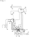
- Engine 100 is an internal combustion engine which ignites an air taken from an air cleaner 102 and an air-fuel mixture injected from an injector 104 with an ignition plug 106 in a combustion chamber and burns them.
- a piston 108 When the air-fuel mixture is burnt, a piston 108 is pressed downward by a combustion pressure, and a crankshaft 110 rotates.
- the burnt air-fuel mixture (exhaust gas) is purified by a three way catalyst 112, and then discharged to the outside of the vehicle.
- the amount of air taken into engine 100 is regulated by a throttle valve 114.
- Engine 100 is controlled by engine ECU 200.
- Engine ECU 200 is connected with a knock sensor 300, a water temperature sensor 302, a crank position sensor 306 provided opposite to a timing rotor 304, a throttle opening sensor 308, a vehicle speed sensor 310, and an ignition switch 312.
- Knock sensor 300 consists of a piezoelectric element. Knock sensor 300 generates voltage by vibration of engine 100. The magnitude of voltage corresponds to the magnitude of vibration. Knock sensor 300 transmits signals indicating voltage to engine ECU 200. Water temperature sensor 302 detects temperature of cooling water inside a water jacket of engine 100, and transmits signals indicating the detection result to engine ECU 200.
- Timing rotor 304 is provided to a crank shaft 110, and rotates together with crank shaft 110. On the outer periphery of timing rotor 304, a plurality of protrusions are provided at predetermined intervals. Crank position sensor 306 is provided opposite to the protrusions of timing rotor 304. When timing rotor 304 rotates, an air gap between the protrusions of timing rotor 304 and crank position sensor 306 changes, so a magnetic flux passing through a coil part of cramp position sensor 306 increases or decreases, whereby electromotive force is generated in the coil part. Cramk position sensor 306 transmits a signal indicating the electromotive force to engine ECU 200. Engine ECU 200 detects a crank angle based on the signal transmitted from crank position sensor 306.
- Throttle opening sensor 308 detects throttle opening and transmits a signal indicating the detection result to engine ECU 200.
- Vehicle speed sensor 310 detects the number of rotations of a wheel (not shown), and transmits a signal indicating the detection result to engine ECU 200.
- Engine ECU 200 calculates the vehicle speed from the number of rotations of the wheel.
- Ignition switch 312 is operated to be turned on by a driver before starting engine 100.
- Engine ECU 200 performs computation based on signals transmitted from each sensor and ignition switch 312 and a map and a program stored on a memory 202, and controls machinery so that engine 100 becomes to be in a desired operating state.
- engine ECU 200 detects a waveform of vibration of engine 100 in a predetermined knock detection gate (a section from a predetermined first crank angle to a predetermined second crank angle) based on the signal and the crank angle transmitted from knock sensor 300, and based on the detected vibration waveform, determines whether knocking occurs in engine 100.
- the knock detection gate in the present embodiment is from a top dead center (0 degree) to 90 degrees in the combustion process. Note that the knock detection gate is not limited to this.
- a vibration waveform is indicated by a value in which an output voltage value (value indicating the intensity of vibration) of knock sensor 300 is integrated by 5 degrees (only for 5 degrees) at the crank angle. Note that the intensity of vibration may be indicated by a value corresponding to an output voltage value of knock sensor 300.
- the detected vibration waveform is compared with the knock waveform model stored on memory 202 of engine ECU 200 as shown in Fig. 3 .
- the knock waveform model is previously created as a model of a vibration waveform of the case where knocking occurs in engine 100.
- the intensity of vibration is indicated as a dimensionless number of 0 to 1, and the intensity of vibration does not correspond to the crank angle unambiguously. That is, in the knock waveform model of the present embodiment, it is defined that the intensity of vibration decreases as the crank angle becomes larger after a peak value of the intensity of vibration, but a crank angle where the intensity of vibration shows a peak value is not defined.
- the knock waveform model of the present embodiment corresponds to vibration after the peak value of the intensity of vibration caused by knocking. Note that a knock waveform model corresponding to vibration after rising of vibration due to knocking may be stored.
- the knock waveform model detects a vibration waveform of engine 100 when forcibly causing knocking, and is created and stored previously based on the vibration waveform.
- a knock waveform model is created by using engine 100 in which the dimension of engine 100 and an output value of knock sensor 300 are medians of dimensional tolerance and tolerance of output values of knock sensor 300 (hereinafter described as a characteristic center engine). That is, a knock waveform model is a vibration waveform when forcibly causing knocking in the characteristic center engine.
- Engine ECU 200 compares a detected waveform and a stored knock waveform model, and determines whether knocking has occurred in engine 100.
- normalization means that the intensity of vibration is indicated as a dimensionless number of 0 to 1 by dividing by the maximum value of the integrated value in the detected vibration waveform by each integration value. Note that a normalization method is not limited to this.
- engine ECU 200 calculates a correlation coefficient K which is a value relating to a deviation between a normalized waveform and a knock waveform model.
- a correlation coefficient K which is a value relating to a deviation between a normalized waveform and a knock waveform model.
- ⁇ S(I) is the total of ⁇ S(I). Note that a method of calculating correlation coefficient K is not limited to this.
- knock intensity N is larger than determination value V(KX)
- engine ECU 200 determines that knocking has occurred in engine 100, so it retards ignition timing. If knock intensity N is smaller than determination value V(KX), engine ECU 200 determines that knocking has not occurred in engine 100, so it advances igniting timing.
- the determination value V(KX) As an initial value of the determination value V(KX), a value previously defined through experimentations or the like is used. However, even in the case where same vibration is caused in engine 100 due to variation in output values of knock sensor 300 or deterioration, the intensity to be detected may fluctuate. In such a case, it is required to correct determination value V(VK) and to determine whether knocking has occurred by using a determination value V(KX) corresponding to the intensity to be detected actually.
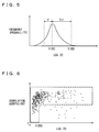
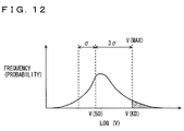
- determination value V(KX) is corrected by using frequency distribution showing the relationship between intensity values LOG(V) which are values that intensities V for the predetermined number of ignition cycles (e.g., 200 cycles) are logarithmically converted and frequency that the intensity values LOG(V) are detected (may be called number of times or probability).
- Intensities V used for calculating intensity values LOG(V) are peak values of the intensities in a predetermined crank angle.
- a median V(50), in which frequency of intensity values LOG(V) are accumulated from the minimum value and becomes 50%, is calculated. Further, a standard deviation ⁇ in the frequency distribution is calculated. A value in which a product of a coefficient U (U is a constant, e.g., U 3) and standard deviation ⁇ is added to median V(50) becomes a knock determination level V(KD). Frequency of intensity values LOG(V) larger than knock determination level V(KD) is determined as frequency in which knocking has occurred.
- intensity values LOG(V) used for preparing frequency distribution intensity values within an area enclosed by a broken line in Fig. 6 are used.
- Fig. 6 is a chart in which calculated intensity values LOG(V) are plotted by each correlation coefficient K in a cycle that intensity values LOG(V) are obtained.
- engine ECU 200 calculates intensity value LOG(V) from intensity V detected based on a signal transmitted from knock sensor 300.
- intensity V is a peak value in a predetermined crank angle.
- engine ECU 200 prepares frequency distribution of intensity values LOG(V).
- engine ECU 200 decides a maximum value V(MAX) of intensity values LOG(V).
- engine ECU 200 calculates median V(50) and standard deviation ⁇ of intensity values LOG(V) not more than maximum value V(MAX)
- engine ECU 200 calculates a knock determination level V(KD) based on median V(50) and standard deviation ⁇ .
- engine ECU 200 determines whether knock determination level V(KD) is smaller than maximum value V(MAX). If knock determination level V(KD) is smaller than maximum value V(MAX) (YES in S112), the processing is moved to S114. If not (NO in S 112), the processing is moved to S 118.
- engine ECU 200 removes V(MAX) decided in S 106 from the frequency distribution.
- engine ECU 200 counts the total frequency of removed maximum values V(MAX) as knock occupancy KC. Then, the processing is returned to S106.
- engine ECU 200 determines whether the knock occupancy KC is larger than a threshold KC(0). If the knock occupancy KC is larger than the threshold KC(0) (YES in S118), the processing is moved to S120. If not (NO in S118), the processing is moved to S122. In S120, engine ECU 200 decrements determination value V(KX) In S122, engine ECU 200 increments determination value V(KX).
- intensity value LOG(V) is calculated from intensity V detected based on a signal transmitted from knock sensor 300 (S100).
- Intensity values LOG(V) smaller than knock determination level V(KD) are not determined as intensity values LOG(V) in a cycle where knocking has occurred. Therefore, when the knock determination level V(KD) becomes higher, frequency determined as knocking having not occurred increases although knocking has occurred.
- knock determination level V(KD) In order to prevent knock determination level V(KD) from becoming higher as described above, if knock determination level V(KD) is smaller than maximum value V(MAX) (YES in S112), maximum value V(MAX) is removed from the frequency distribution (S 114). The total frequency of removed maximum values V(MAX) is counted as knock occupancy KC (S116).
- maximum value V(MAX) is redetermined (S106). In other words, maximum value V(MAX) is corrected to be smaller in the frequency distribution.
- knock determination level V(KD) is recalculated (S110). That is, knock determination level V(KD) in the frequency distribution for intensity values LOG(V) not more than redetermined maximum value V(MAX) is recalculated. As long as knock determination level V(KD) is smaller than maximum value V(MAX) (YES in S112), processing from S106 to S 116 is repeated.
- knock determination level V(KD) becomes lower, as shown in Fig. 11 .
- the reduction rate of maximum value V(MAX) is larger than the reduction rate of knock determination level V(KD), so there is a point where the both coincide.
- knock occupancy KC knocking occurrence frequency
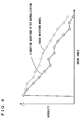
- Fig. 13 shows a transition of knock occupancy KC when knock occupancy KC is counted, by using knock determination level V(KD) calculated while not removing maximum values V(MAX).
- V(KD) the audible knock intensity (intensity level audible by passengers) increases from a state of no knocking, knock occupancy KC increases.
- knock determination level V(KD) increases as maximum value V(MAX) increases, so if the audible knock intensity is too large, knock occupancy KC decreases in turn.
- knock determination level V(KD) is recalculated by removing maximum values V(MAX) until maximum value V(MAX) and knock determination level V(KD) coincide as shown in Fig. 14 , knock occupancy KC increases as the audible knock intensity increases. Thereby, it is possible to detect knock occupancy KC with high accuracy.
- knock occupancy KC is smaller than threshold KC(0) (NO in S118)
- the knocking occurrence frequency can be said as being within the allowable value. In such a case, it can be said that it is a state where output of engine 100 can be further increased.
- determination value V(KX) is incremented (S122). Therefore, it is possible to increase output of engine by suppressing frequency that knocking is determined to have occurred and retarding ignition timing.
- the engine ECU of the knocking occurrence number determination device removes maximum values V(MAX) (first value) until maximum value V(MAX) and knock determination level V(KD) (second value) coincide, and calculates knock determination level V(KD) (second value).
- the total frequency of maximum values V(MAX) removed until maximum value V(MAX) (first value) and knock determination level V(KD) (second value) coincide is counted as knock occupancy KC.
- knock determination level V(KD) (second value) increases, whereby it is possible to suppress a drop of knock occupancy KC regardless of knocking having occurred. Therefore, it is possible to determine the number of times that knocking has occurred with high accuracy.
- knock determination level V(KD) is recalculated by removing maximum values V(MAX) until knock determination level V(KD) and maximum value V(MAX) coincide
- knock determination level V(KD) may be recalculated by removing maximum values V(MAX) until knock determination level V(KD) becomes not less than maximum value V(MAX).
- knock determination level V(KD) may be recalculated by removing maximum values V(MAX) until knock determination level V(KD) coincide with maximum value V(MAX) or knock determination level V(KD) becomes not more than maximum value V(MAX).
- knock determination level V(KD) may be recalculated by removing maximum values V(MAX) until the deviation between knock determination level V(KD) and maximum value V(MAX) becomes smaller than the predetermined deviation.
- a peak value of the intensity detected by knock sensor 300 is used as intensity V used for calculating intensity values LOG(V)
- a peak value of the intensity of vibration components of an in-cylinder pressure detected by an in-cylinder pressure sensor for detecting an in-cylinder pressure of engine 100 may be used.
- the in-cylinder pressure sensor may be provided integrally with an ignition plug provided at the cylinder center part in a planar view so as to detect the intensity of vibration components of pressure of the cylinder center part.
- intensity V used for calculating intensity values LOG(V) a product of a peak value of the intensity detected by knock sensor 300 and correlation coefficient K in a cycle in which the peak value is detected may be used.
Landscapes
- Chemical & Material Sciences (AREA)
- Engineering & Computer Science (AREA)
- Combustion & Propulsion (AREA)
- Physics & Mathematics (AREA)
- General Physics & Mathematics (AREA)
- Combined Controls Of Internal Combustion Engines (AREA)
Claims (5)
- Klopfzustandsbestimmungsvorrichtung in einer Brennkraftmaschine (100), die Folgendes aufweist:eine Erfassungseinrichtung (300) zum Erfassen einer Vielzahl von Intensitätswerten, die eine Intensität von einer Vibration betreffen, die in der Brennkraftmaschine (100) verursacht wird;eine Berechnungseinrichtung (200), die angepasst ist, um ein Klopfbestimmungsniveau durch ein Berechnen eines Standardabweichungswerts und eines Medians von mindestens einem Teil der Vielzahl von Intensitätswerten und ein Addieren eines Produkts aus einem vorbestimmten Koeffizienten und der Standardabweichung zu dem Median zu berechnen;eine Entfernungseinrichtung (200), die angepasst ist, um Höchstwerte von Intensitätswerten, die zum Berechnen des Klopfbestimmungsniveaus verwendet werden, wiederholt zu entfernen, derart, dass ein Höchstwert von Intensitätswerten, die zum Berechnen des Klopfbestimmungsniveaus verwendet werden, nicht geringer als das Klopfbestimmungsniveau wird, wenn der Höchstwert der Intensitätswerte, die zum Berechnen des Klopfbestimmungsniveaus verwendet werden, kleiner als das Klopfbestimmungsniveau ist, und der Höchstwert von Intensitätswerten, die zum Berechnen des Klopfbestimmungsniveaus verwendet werden, nicht mehr als das Klopfbestimmungsniveau wird, wenn der Höchstwert der Intensitätswerte, die zum Berechnen des Klopfbestimmungsniveaus verwendet werden, größer als das Klopfbestimmungsniveau ist, wodurch die Intensitätswerte, die zum Berechnen des Klopfbestimmungsniveaus verwendet werden, verringert werden; undeine Bestimmungseinrichtung (200), die angepasst ist, um einen Klopfauftrittszustand basierend auf einem Intensitätswert zu bestimmen, der größer als mindestens entweder der Höchstwert der Intensitätswerte, die zum Berechnen des Klopfbestimmungsniveaus verwendet werden, oder das Klopfbestimmungsniveau ist.
- Klopfzustandsbestimmungsvorrichtung gemäß Anspruch 1, wobei
die Bestimmungseinrichtung (200) eine Anzahlbestimmungseinrichtung (200) umfasst, die angepasst ist, um zu bestimmen, dass eine Anzahl von Intensitätswerten, die größer sind als mindestens ein Wert von entweder dem Höchstwert in den Intensitätswerten, die zum Berechnen des Klopfbestimmungsniveaus verwendet werden, oder dem Klopfbestimmungsniveau, eine Anzahl von Malen ist, bei denen ein Klopfen aufgetreten ist. - Klopfzustandsbestimmungsvorrichtung gemäß Anspruch 1, des Weiteren mit einer Intensitätserfassungseinrichtung (200), die angepasst ist, um eine Intensität von einer Vibration zu erfassen, die durch eine Verbrennung der Brennkraftmaschine (100) verursacht wird, wobei
der Intensitätswert ein Wert ist, in dem ein Spitzenwert einer Intensität von einer Vibration der Brennkraftmaschine (100) in einem vorbestimmten Kurbelwinkel logarithmisch umgewandelt ist. - Klopfzustandsbestimmungsvorrichtung gemäß Anspruch 1, des Weiteren mit:einer Intensitätserfassungseinrichtung (200) zum Erfassen einer Intensität von einer Vibration, die durch eine Verbrennung der Brennkraftmaschine (100) verursacht wird;einer Speichereinrichtung (200), die angepasst ist, um im Voraus eine Wellenform von einer Vibration der Brennkraftmaschine (100) in einem vorbestimmten Kurbelwinkel zu speichern;einer Wellenformerfassungseinrichtung (200) zum Erfassen einer Wellenform von einer Vibration der Brennkraftmaschine (100) in einem vorbestimmten Kurbelwinkel; undeiner Abweichungsberechnungseinrichtung (200), die angepasst ist, um einen Wert zu berechnen, der eine Abweichung zwischen der gespeicherten Wellenform und der erfassten Wellenform betrifft, basierend auf einem Ergebnis von einem Vergleichen der gespeicherten Wellenform mit der erfassten Wellenform, wobeider Intensitätswert ein Wert ist, in dem ein Produkt aus einem Spitzenwert der Intensität von einer Vibration der Brennkraftmaschine (100) in dem vorbestimmten Kurbelwinkel und einem Wert, der die Abweichung betrifft, logarithmisch umgewandelt ist.
- Klopfzustandsbestimmungsvorrichtung gemäß Anspruch 1, des Weiteren mit einer Intensitätserfassungseinrichtung (200), die angepasst ist, um eine Intensität von einer Vibration eines Zylinderinnendrucks der Brennkraftmaschine (100) zu erfassen, wobei
der Intensitätswert ein Wert ist, in dem ein Spitzenwert der Intensität von einer Vibration des Zylinderinnendrucks in einem vorbestimmten Kurbelwinkel logarithmisch umgewandelt ist.
Applications Claiming Priority (2)
| Application Number | Priority Date | Filing Date | Title |
|---|---|---|---|
| JP2005188618A JP4404811B2 (ja) | 2005-06-28 | 2005-06-28 | ノッキング状態判定装置 |
| PCT/JP2006/312951 WO2007001040A1 (en) | 2005-06-28 | 2006-06-22 | Knocking state determination device |
Publications (3)
| Publication Number | Publication Date |
|---|---|
| EP1896816A1 EP1896816A1 (de) | 2008-03-12 |
| EP1896816B1 true EP1896816B1 (de) | 2016-04-13 |
| EP1896816B8 EP1896816B8 (de) | 2016-06-22 |
Family
ID=36997728
Family Applications (1)
| Application Number | Title | Priority Date | Filing Date |
|---|---|---|---|
| EP06767568.6A Not-in-force EP1896816B8 (de) | 2005-06-28 | 2006-06-22 | Vorrichtung zur bestimmung des klopfzustands |
Country Status (5)
| Country | Link |
|---|---|
| US (2) | US7424820B2 (de) |
| EP (1) | EP1896816B8 (de) |
| JP (1) | JP4404811B2 (de) |
| CN (1) | CN101213433B (de) |
| WO (1) | WO2007001040A1 (de) |
Families Citing this family (17)
| Publication number | Priority date | Publication date | Assignee | Title |
|---|---|---|---|---|
| JP4404811B2 (ja) * | 2005-06-28 | 2010-01-27 | トヨタ自動車株式会社 | ノッキング状態判定装置 |
| JP4475675B2 (ja) * | 2007-05-11 | 2010-06-09 | 三菱電機株式会社 | 内燃機関のノック検出装置 |
| JP4680248B2 (ja) * | 2007-11-13 | 2011-05-11 | トヨタ自動車株式会社 | 内燃機関の点火時期制御装置および点火時期制御方法 |
| JP4980956B2 (ja) * | 2008-03-03 | 2012-07-18 | トヨタ自動車株式会社 | 内燃機関の点火時期制御装置 |
| DE102009019283B4 (de) * | 2008-05-01 | 2015-06-03 | GM Global Technology Operations LLC (n. d. Ges. d. Staates Delaware) | Motorklopfdiagnose |
| US9157825B2 (en) | 2008-05-01 | 2015-10-13 | GM Global Technology Operations LLC | Engine knock diagnostic |
| JP4772846B2 (ja) * | 2008-10-01 | 2011-09-14 | 川崎重工業株式会社 | ガスエンジンのノッキング制御装置 |
| JP4703731B2 (ja) * | 2009-01-06 | 2011-06-15 | 三菱電機株式会社 | 内燃機関の制御装置 |
| FR2952679B1 (fr) * | 2009-11-13 | 2012-02-24 | Inst Francais Du Petrole | Procede de detection de combustion anormale pour moteurs a combustion interne a partir de modelisations de distributions d'indicateurs de combustion |
| JP5554295B2 (ja) * | 2011-07-28 | 2014-07-23 | 日立オートモティブシステムズ株式会社 | 内燃機関の燃焼騒音検出方法及び燃焼騒音検出装置並びに内燃機関の制御装置 |
| JP5839972B2 (ja) * | 2011-12-12 | 2016-01-06 | 三菱電機株式会社 | 内燃機関の制御装置 |
| JP6136341B2 (ja) * | 2013-02-19 | 2017-05-31 | トヨタ自動車株式会社 | 内燃機関の異常燃焼検出装置 |
| US9441556B2 (en) | 2013-03-15 | 2016-09-13 | GM Global Technology Operations LLC | Noise updating systems and methods |
| DE102013221993A1 (de) * | 2013-10-29 | 2015-04-30 | Robert Bosch Gmbh | Verfahren und Vorrichtung zur Erkennung eines Klopfens einer Brennkraftmaschine, vorzugsweise eines Benzinmotors |
| CN106030272B (zh) * | 2013-11-25 | 2019-07-16 | Sem公司 | 使用爆震数据的发动机管理方法 |
| JP6288699B2 (ja) * | 2014-01-10 | 2018-03-07 | 三菱重工業株式会社 | 内燃機関のノッキング判定装置及びノッキング制御装置 |
| US11982246B2 (en) * | 2020-11-23 | 2024-05-14 | Transportation Ip Holdings, Llc | Methods and systems for engine |
Family Cites Families (19)
| Publication number | Priority date | Publication date | Assignee | Title |
|---|---|---|---|---|
| EP0550411B1 (de) * | 1988-06-14 | 1997-03-05 | Nippondenso Co., Ltd. | Klopfregelung bei Brennkraftmaschinen |
| JP2605805B2 (ja) | 1988-06-15 | 1997-04-30 | 株式会社デンソー | 内燃機関用ノック制御装置 |
| JP2730215B2 (ja) * | 1989-10-03 | 1998-03-25 | 株式会社デンソー | エンジン用ノック制御装置 |
| GB2259365B (en) * | 1991-09-04 | 1995-08-02 | Nippon Denso Co | Knock control apparatus for an internal combustion engine |
| JP3084889B2 (ja) * | 1992-03-12 | 2000-09-04 | 株式会社デンソー | 内燃機関用ノック制御装置 |
| DE19946346A1 (de) * | 1999-09-28 | 2001-03-29 | Bosch Gmbh Robert | Verfahren zur Klopferkennung |
| JP3753583B2 (ja) | 2000-02-15 | 2006-03-08 | 株式会社デンソー | 内燃機関用ノック制御装置 |
| JP4465928B2 (ja) | 2001-07-04 | 2010-05-26 | 株式会社デンソー | 内燃機関のノック制御装置 |
| US6688286B2 (en) * | 2001-05-29 | 2004-02-10 | Denso Corporation | Knock control apparatus for engine |
| JP4560241B2 (ja) * | 2001-06-06 | 2010-10-13 | 富士通テン株式会社 | 内燃機関のノッキング判定装置 |
| US6845312B1 (en) * | 2003-08-14 | 2005-01-18 | Brunswick Corporation | Method for detecting engine knock |
| JP4410674B2 (ja) * | 2004-04-22 | 2010-02-03 | トヨタ自動車株式会社 | 内燃機関のノッキング判定装置およびその装置を含む点火制御システム |
| EP2532864B1 (de) * | 2004-06-04 | 2014-08-27 | Nissan Motor Co., Ltd. | Motorsteuerungsvorrichtung und Steuerungsverfahren |
| JP4605642B2 (ja) * | 2004-12-14 | 2011-01-05 | 株式会社デンソー | 内燃機関のノック判定装置 |
| JP4557709B2 (ja) * | 2004-12-24 | 2010-10-06 | トヨタ自動車株式会社 | 内燃機関のノッキング判定装置 |
| JP4549920B2 (ja) * | 2005-04-27 | 2010-09-22 | トヨタ自動車株式会社 | 内燃機関のノッキング判定装置 |
| JP4404811B2 (ja) * | 2005-06-28 | 2010-01-27 | トヨタ自動車株式会社 | ノッキング状態判定装置 |
| US7222607B2 (en) * | 2005-08-05 | 2007-05-29 | Gm Global Technology Operations, Inc. | DSP-based engine knock detection including knock sensor and circuit diagnostics |
| JP4342520B2 (ja) * | 2006-01-27 | 2009-10-14 | トヨタ自動車株式会社 | 内燃機関の点火時期制御装置 |
-
2005
- 2005-06-28 JP JP2005188618A patent/JP4404811B2/ja not_active Expired - Fee Related
-
2006
- 2006-06-22 EP EP06767568.6A patent/EP1896816B8/de not_active Not-in-force
- 2006-06-22 CN CN2006800237985A patent/CN101213433B/zh not_active Expired - Fee Related
- 2006-06-22 WO PCT/JP2006/312951 patent/WO2007001040A1/en not_active Ceased
- 2006-06-27 US US11/475,231 patent/US7424820B2/en active Active
-
2008
- 2008-08-14 US US12/191,327 patent/US7643932B2/en active Active
Also Published As
| Publication number | Publication date |
|---|---|
| US7643932B2 (en) | 2010-01-05 |
| EP1896816A1 (de) | 2008-03-12 |
| WO2007001040A1 (en) | 2007-01-04 |
| CN101213433A (zh) | 2008-07-02 |
| US20080306677A1 (en) | 2008-12-11 |
| EP1896816B8 (de) | 2016-06-22 |
| JP4404811B2 (ja) | 2010-01-27 |
| JP2007009739A (ja) | 2007-01-18 |
| CN101213433B (zh) | 2010-12-08 |
| US7424820B2 (en) | 2008-09-16 |
| US20070084267A1 (en) | 2007-04-19 |
Similar Documents
| Publication | Publication Date | Title |
|---|---|---|
| US7643932B2 (en) | Knocking state determination device | |
| EP1896817B1 (de) | Vorrichtung zur bestimmung eines klopfstatus | |
| EP1979606B1 (de) | Verfahren und vorrichtung zur steuerung des zündzeitpunkts durch klopfsteuerung in einem verbrennungsmotor | |
| US7478624B2 (en) | Ignition timing control device of internal combustion engine | |
| EP1959122B1 (de) | Vorrichtung zur beurteilung des klopfens einer brennkraftmaschine und verfahren zur beurteilung des klopfens | |
| US8000884B2 (en) | Device and method for controlling ignition timing of internal combustion engine | |
| US7669459B2 (en) | Knocking determination device for internal combustion engine | |
| US7478622B2 (en) | Device and method for determining knocking of internal combustion engine | |
| US7500468B2 (en) | Device and method for determining knocking of internal combustion engine | |
| EP2032961B1 (de) | Vorrichtung und verfahren zur klopfbestimmung in einem verbrennungsmotor | |
| KR100929994B1 (ko) | 내연기관의 노킹 판정 장치 및 방법 | |
| US8005607B2 (en) | Device and method for controlling ignition timing of internal combustion engine | |
| US7822533B2 (en) | Knocking determination device and knocking determination method of internal combustion engine |
Legal Events
| Date | Code | Title | Description |
|---|---|---|---|
| PUAI | Public reference made under article 153(3) epc to a published international application that has entered the european phase |
Free format text: ORIGINAL CODE: 0009012 |
|
| 17P | Request for examination filed |
Effective date: 20071128 |
|
| AK | Designated contracting states |
Kind code of ref document: A1 Designated state(s): DE FR IT |
|
| DAX | Request for extension of the european patent (deleted) | ||
| 17Q | First examination report despatched |
Effective date: 20080416 |
|
| DAX | Request for extension of the european patent (deleted) | ||
| RBV | Designated contracting states (corrected) |
Designated state(s): DE FR IT |
|
| RAP1 | Party data changed (applicant data changed or rights of an application transferred) |
Owner name: TOYOTA JIDOSHA KABUSHIKI KAISHA Owner name: NIPPON SOKEN, INC. Owner name: DENSO CORPORATION |
|
| GRAP | Despatch of communication of intention to grant a patent |
Free format text: ORIGINAL CODE: EPIDOSNIGR1 |
|
| INTG | Intention to grant announced |
Effective date: 20151103 |
|
| GRAS | Grant fee paid |
Free format text: ORIGINAL CODE: EPIDOSNIGR3 |
|
| GRAA | (expected) grant |
Free format text: ORIGINAL CODE: 0009210 |
|
| RIN1 | Information on inventor provided before grant (corrected) |
Inventor name: TAKEMURA, YUICHI Inventor name: OE, SHUHEI, C/O NIPPON SOKEN, INC. Inventor name: MURATE, NOBUYUKI, C/O NIPPON SOKEN, INC. Inventor name: IWADE, KIYOSHI, C/O NIPPON SOKEN, INC. Inventor name: KASASHIMA, KENJI Inventor name: KANEKO, RIHITO |
|
| AK | Designated contracting states |
Kind code of ref document: B1 Designated state(s): DE FR IT |
|
| RIN2 | Information on inventor provided after grant (corrected) |
Inventor name: KANEKO, RIHITO Inventor name: TAKEMURA, YUICHI Inventor name: MURATE, NOBUYUKI Inventor name: OE, SHUHEI Inventor name: KASASHIMA, KENJI Inventor name: IWADE, KIYOSHI |
|
| REG | Reference to a national code |
Ref country code: DE Ref legal event code: R096 Ref document number: 602006048681 Country of ref document: DE |
|
| PG25 | Lapsed in a contracting state [announced via postgrant information from national office to epo] |
Ref country code: IT Free format text: LAPSE BECAUSE OF FAILURE TO SUBMIT A TRANSLATION OF THE DESCRIPTION OR TO PAY THE FEE WITHIN THE PRESCRIBED TIME-LIMIT Effective date: 20160413 |
|
| REG | Reference to a national code |
Ref country code: DE Ref legal event code: R097 Ref document number: 602006048681 Country of ref document: DE |
|
| PLBE | No opposition filed within time limit |
Free format text: ORIGINAL CODE: 0009261 |
|
| STAA | Information on the status of an ep patent application or granted ep patent |
Free format text: STATUS: NO OPPOSITION FILED WITHIN TIME LIMIT |
|
| REG | Reference to a national code |
Ref country code: DE Ref legal event code: R084 Ref document number: 602006048681 Country of ref document: DE |
|
| 26N | No opposition filed |
Effective date: 20170116 |
|
| REG | Reference to a national code |
Ref country code: FR Ref legal event code: ST Effective date: 20170228 |
|
| PG25 | Lapsed in a contracting state [announced via postgrant information from national office to epo] |
Ref country code: FR Free format text: LAPSE BECAUSE OF NON-PAYMENT OF DUE FEES Effective date: 20160630 |
|
| PGFP | Annual fee paid to national office [announced via postgrant information from national office to epo] |
Ref country code: DE Payment date: 20230620 Year of fee payment: 18 |
|
| REG | Reference to a national code |
Ref country code: DE Ref legal event code: R119 Ref document number: 602006048681 Country of ref document: DE |
|
| PG25 | Lapsed in a contracting state [announced via postgrant information from national office to epo] |
Ref country code: DE Free format text: LAPSE BECAUSE OF NON-PAYMENT OF DUE FEES Effective date: 20250101 |