EP1896831B1 - Système de détection de fluorescence multicolore à optique fixe et à sélectivité spatiale pour dispositif microfluidique à canaux multiples et procédé de détection - Google Patents
Système de détection de fluorescence multicolore à optique fixe et à sélectivité spatiale pour dispositif microfluidique à canaux multiples et procédé de détection Download PDFInfo
- Publication number
- EP1896831B1 EP1896831B1 EP06773974.8A EP06773974A EP1896831B1 EP 1896831 B1 EP1896831 B1 EP 1896831B1 EP 06773974 A EP06773974 A EP 06773974A EP 1896831 B1 EP1896831 B1 EP 1896831B1
- Authority
- EP
- European Patent Office
- Prior art keywords
- detection system
- ball lens
- ball
- optical fiber
- diameter
- Prior art date
- Legal status (The legal status is an assumption and is not a legal conclusion. Google has not performed a legal analysis and makes no representation as to the accuracy of the status listed.)
- Active
Links
Images


Classifications
-
- G—PHYSICS
- G01—MEASURING; TESTING
- G01N—INVESTIGATING OR ANALYSING MATERIALS BY DETERMINING THEIR CHEMICAL OR PHYSICAL PROPERTIES
- G01N21/00—Investigating or analysing materials by the use of optical means, i.e. using sub-millimetre waves, infrared, visible or ultraviolet light
- G01N21/62—Systems in which the material investigated is excited whereby it emits light or causes a change in wavelength of the incident light
- G01N21/63—Systems in which the material investigated is excited whereby it emits light or causes a change in wavelength of the incident light optically excited
- G01N21/64—Fluorescence; Phosphorescence
- G01N21/645—Specially adapted constructive features of fluorimeters
- G01N21/6456—Spatial resolved fluorescence measurements; Imaging
-
- G—PHYSICS
- G01—MEASURING; TESTING
- G01N—INVESTIGATING OR ANALYSING MATERIALS BY DETERMINING THEIR CHEMICAL OR PHYSICAL PROPERTIES
- G01N21/00—Investigating or analysing materials by the use of optical means, i.e. using sub-millimetre waves, infrared, visible or ultraviolet light
- G01N21/62—Systems in which the material investigated is excited whereby it emits light or causes a change in wavelength of the incident light
- G01N21/63—Systems in which the material investigated is excited whereby it emits light or causes a change in wavelength of the incident light optically excited
- G01N21/64—Fluorescence; Phosphorescence
- G01N2021/6417—Spectrofluorimetric devices
-
- G—PHYSICS
- G01—MEASURING; TESTING
- G01N—INVESTIGATING OR ANALYSING MATERIALS BY DETERMINING THEIR CHEMICAL OR PHYSICAL PROPERTIES
- G01N21/00—Investigating or analysing materials by the use of optical means, i.e. using sub-millimetre waves, infrared, visible or ultraviolet light
- G01N21/62—Systems in which the material investigated is excited whereby it emits light or causes a change in wavelength of the incident light
- G01N21/63—Systems in which the material investigated is excited whereby it emits light or causes a change in wavelength of the incident light optically excited
- G01N21/64—Fluorescence; Phosphorescence
- G01N2021/6417—Spectrofluorimetric devices
- G01N2021/6423—Spectral mapping, video display
-
- G—PHYSICS
- G01—MEASURING; TESTING
- G01N—INVESTIGATING OR ANALYSING MATERIALS BY DETERMINING THEIR CHEMICAL OR PHYSICAL PROPERTIES
- G01N21/00—Investigating or analysing materials by the use of optical means, i.e. using sub-millimetre waves, infrared, visible or ultraviolet light
- G01N21/62—Systems in which the material investigated is excited whereby it emits light or causes a change in wavelength of the incident light
- G01N21/63—Systems in which the material investigated is excited whereby it emits light or causes a change in wavelength of the incident light optically excited
- G01N21/64—Fluorescence; Phosphorescence
- G01N21/645—Specially adapted constructive features of fluorimeters
- G01N2021/6463—Optics
- G01N2021/6478—Special lenses
-
- G—PHYSICS
- G01—MEASURING; TESTING
- G01N—INVESTIGATING OR ANALYSING MATERIALS BY DETERMINING THEIR CHEMICAL OR PHYSICAL PROPERTIES
- G01N21/00—Investigating or analysing materials by the use of optical means, i.e. using sub-millimetre waves, infrared, visible or ultraviolet light
- G01N21/62—Systems in which the material investigated is excited whereby it emits light or causes a change in wavelength of the incident light
- G01N21/63—Systems in which the material investigated is excited whereby it emits light or causes a change in wavelength of the incident light optically excited
- G01N21/64—Fluorescence; Phosphorescence
- G01N21/645—Specially adapted constructive features of fluorimeters
- G01N2021/6484—Optical fibres
Definitions
- the present invention relates to a system for spatially selective, fixed-optics fluorescence detection in a multichannel polymeric microfluidic device, and a method for performing spatially selective, fixed-optics fluorescence detection.
- Microfluidic devices are characterized by having one or more channels with at least one dimension less than 1 mm (typically much less than 1 mm). Common fluids used in microfluidic devices include biofluids such as whole blood samples, bacterial cell suspensions, protein or antibody solutions and various buffers. Microfluidic devices can be used for a variety of measurements including molecular diffusion coefficients, fluid viscosity, pH, chemical binding coefficients and enzyme reaction kinetics.
- microfluidic devices include capillary electrophoresis, isoelectric focusing, immunoassays, flow cytometry, injection of protein samples for analysis via mass spectrometry, DNA analysis, cell manipulation, cell separation, cell patterning and chemical gradient formation. Many of these applications have utility for clinical diagnostics.
- microfluidic devices to conduct biomedical research and create clinically useful technologies has a number of significant advantages.
- volume of fluids within these channels is very small, generally sub-microliter, the amount of reagents and analytes used is quite small. This is especially significant for expensive reagents or samples.
- Microfluidic devices can be fabricated using processes developed for the microelectronics industry to create tiny chambers and fluidic networks in quartz, silica, glass, or polymeric chips. Another advantage is that the fabrication techniques used to construct microfluidic devices are very amenable both to highly elaborate, multiplexed devices and also to mass production. Polymeric or plastic microfluidic devices have the additional advantage of being relatively inexpensive to manufacture. In a manner similar to that for microelectronics, microfluidic technologies enable the fabrication of highly integrated devices for performing several different functions on the same substrate chip.
- Microfluidic devices can direct the flow of liquid chemical reagents similar to the way semiconductors direct the flow of electrons. Reagents can be diluted, mixed, or reacted with other reagents prior to analysis by capillary electrophoresis or electrochromatography - all on a single chip. As such, microfluidic devices can be designed to accommodate virtually any analytic biochemical process. Plastic, or polymeric, microfluidic devices are particularly attractive because of the low cost and relative ease of manufacture compared to glass devices. However, laser-induced fluorescence detection in polymeric microchips presents some unique challenges.
- a plastic substrate in which the microchannels are formed
- a plastic substrate is substantially more fluorescent than freestanding silica capillaries
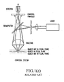
- spatial selection is required to isolate the fluorescent signal originating from within the microchannel from fluorescence originating in the substrate material. In the past, this has typically been achieved with a confocal system; measurement of multiple channels then requires mechanical scanning of the optical elements. Examples of two different conventional laser-induced fluorescence detection systems are shown in FIG. 1(a) and (b) .
- FIG. 1(a) shows a conventional confocal arrangement from Leica Microsystems ( http://www.confocal-microscopy.com/website/sc_llt.nsf ).
- Leica Microsystems http://www.confocal-microscopy.com/website/sc_llt.nsf ).
- all structures out of focus are suppressed at image formation. This is obtained by an arrangement of diaphragms, which, at optically conjugated points of the path of rays, act as a point light source and as a point detector respectively. Rays from out-of-focus areas are suppressed by the detection pinhole.
- the depth of the focal plane is, besides the wavelength of light, determined in particular by the numerical aperture of the objective used and the diameter of the diaphragm. With a wider detection pinhole the confocal effect can be reduced.
- the image point is moved across the specimen by mirror scanners.
- the emitted/reflected light passing through the detector pinhole is transformed into electrical
- confocal arrangements such as that shown in FIG. 1(a)
- a system is complex and includes moving parts.
- FIG. 1(b) shows a conventional ball lens - optical coupling arrangement, with a 2 mm diameter ball lens 110 and a 1 mm core diameter fiber 60, and the ball lens 110 positioned to collimate light from source S.
- One advantage of a ball lens system over a confocal system is simplicity in assembly and alignment, as well as compactness.
- the working distance d2 is very short, thus making this arrangement unsuitable in many situations.
- a conventional ball lens system were used in an epi-illumination setup for measurements on a plastic microfluidic device, the background fluorescence from the substrate would severely limit the sensitivity.
- US patent No. 6,184,990 discloses a spatially selective fluorescence detection system comprising: a capillary flow cell; an optical fiber; and a ball lens mounted adjacent to one end of the optical fiber for receiving light from a spatially selected volume in the flow cell, the ball lens having a diameter larger than the diameter of the optical fiber; where the ball lens and the one end of the optical fiber being separated by a distance greater than a radius of the ball lens, so that the light emitted from the spatially selected volume and received by the ball lens converges onto the one end of the optical fiber.
- EP 0 973 040 discloses a spatially selective fluorescence detection system comprising: multiple detection optical fibers; an array including multiple ball lenses separated by predetermined distances, each ball lens being positioned to receive emitted light from one of multiple spatially selected volumes; wherein the multiple detection optical fibers each correspond to one of the ball lenses and one of the spatially selected volumes, the ball lenses converging the light emitted from the selected volumes onto one end of each of the corresponding detection optical fibers.
- plastic microchips remain attractive because of the low cost and relative ease of manufacture compared to glass systems, many drawbacks exist in using plastic microchips with conventional laser-induced fluorescence detection systems.
- modem technology requires new detection systems that are simple and inexpensive to construct and operate, particularly when performing multiplexed measurements, in microchips with multiple channels.
- the invention relates to a spatially selective fluorescence detection system comprising:
- the invention relates to a method for analysing a plurality of spatially selected volumes by fluorescence, comprising:
- FIG. 1(a) is a schematic showing a conventional confocal lens arrangement known in the related art
- FIG. 1(b) is a schematic showing a conventional ball lens-optical fiber coupling arrangement known in the related art
- FIG. 1(c) is a schematic showing a ball lens-optical fiber coupling arrangement of the present invention.
- FIG. 2(a) is a schematic of excitation and detection components of the present invention for exciting and detecting fluorescence in a single channel; and FIG. 2(b) illustrates a limit of detection for dye in a single polymeric microchannel for the fluorescence detection system of the present invention.
- FIG. 3(a) is a schematic for separation of a single laser excitation beam into eight spots using two cylindrical lenses and an array of eight plano-convex lenses for use in a eight channel detection system;
- FIG. 3(b) illustrates the use of such lenses to generate eight focused spots onto an eight channel microfluidic device from a single 633nm laser beam.
- FIGS. 4(a) and (b) are top down and side views of a holder for eight ball lenses and eight optical fibers for detecting luminescence or fluorescence.
- FIG. 5(a) is a schematic of CCD output, with the detected output from eight independent channels arrayed from top to bottom, each with longer wavelength light on the left; and FIG. 5(b) is a demonstration measurement of eight independent spectra with an experimental system of the present invention.
- FIGS. 6(a) and (b) show the calculated coupling efficiency of light into the ball lens-fiber system as a function of source position in air, with FIG. 6(a) showing, transmitted intensity as a function of source depth, and FIG. 6(b) showing transmitted intensity as a function of off-axis distance.
- FIG. 7 is an illustration of detection system.
- FIG. 8 is another illustration of the detection system.
- FIG. 9 illustrates an alternative embodiment of laser excitation, with a separate optical fiber for laser excitation incorporated into a variant of the ball lens/detection fiber holder shown in FIGS. 4(a) and (b).
- the present invention is directed to a system and method for sensitive, spatially resolved and spectrally resolved laser-induced fluorescence detection from multiple microfluidic channels that substantially obviates one or more problems due to limitations and disadvantages of the related art. Any particular embodiment of the invention might not solve every problem of the related art described above.
- One embodiment of the present invention involves simultaneous detection from a plurality of microchannels in a plastic microchip for DNA analysis. Multiple colors of fluorescence may be detected in each microchannel.
- the detector of the present invention may be applied to fluorescence or luminescence detection for any microchip-based analysis in any transparent substrate.
- the apparatus of the invention is robust, versatile, and contains only fixed optical parts.
- the economies of parallel analysis and the importance of spatial selectivity make the method of the present invention very useful for polymeric substrates with multiple microchannels.
- spatial selectivity is important because plastic or polymeric materials tend to be fluorescent; thus there is a need to isolate signal originating from the analytic channel from fluorescence of substrate material.
- Parallel detection permits the running of multiple analyses simultaneously, thereby increasing throughput, and saving instrument and operator time.
- FIGS. 1(c) and 2 The detection configuration of the present invention is depicted in FIGS. 1(c) and 2 . A single microchannel is shown for simplicity.
- FIG. 1(c) shows the quasi-focusing configuration of the present invention, with a 200 ⁇ m diameter fiber 60, the ball lens 110 and fiber 60 being separated by distance d1 in the axial direction of the fiber.
- the distance d1 from the ball lens 110 to the optical fiber 60 is determined by treating the sample S as a point source and positioning the ball lens 110 relative to the sample such that a circle of light defined by the intersection of a marginal transmitted ray and the caustic (the caustic being the envelope of the transmitted rays) has a diameter equal to that of the optical fiber 60, and the angle of the marginal transmitted ray as it enters the optical fiber is equal to the maximum acceptance angle of the optical fiber 60.
- the working distance d2 i.e., distance in the axial direction between source S and ball lens 110
- working distance d2 with the ball lens - optical fiber coupling arrangement of the present invention is substantially smaller than working distance d2 with the ball lens - optical fiber coupling arrangement of the present invention.
- FIG. 1(b) more light can be collected using the conventional configuration using a large-diameter fiber 60, coupling light from this fiber into a spectrograph is not efficient.
- the ball lens system of the present invention does not have a single focus; light transmitted up the fiber 60 comes from rays that converge at different points along the axis of the fiber 60 due to spherical aberrations.
- the present configuration takes advantage of the spherical aberrations inherent in ball lenses to collect more light into the fiber.
- a free space laser excitation 10 is focused on a selected volume or sample (source) S located in a central volume of microchannel 50 in a microfluidic device (microchip) 100.
- the selected volume S has a height and width comparable to those of the microchannel 50, and the microchannel 50 is positioned such that light intensity from the selected volume S is maximized. In practice, this will involve moving the channel 50 slightly farther away from the ball lens 110 relative to the point source position used when determining the ball lens - fiber spacing.
- the 2 mm ball lens 110 may be made out of LaSFN9, for example.
- LaSFN9 is a type of glass having a relatively high index of refraction ( ⁇ 1.85).
- Other materials/glasses may also be used, though the higher-index (i.e., more refractive) materials may collect more light.
- the signal is spectrally dispersed with an imaging spectrograph 80 (An Oriel FICS, for example) and the spectra are recorded with a camera 90, which preferably is a charged-coupled device, and preferably is cooled to minimize noise and increase sensitivity.
- a camera 90 which preferably is a charged-coupled device, and preferably is cooled to minimize noise and increase sensitivity.
- the camera 90 converts the optical signal into an electronic signal. Cooling reduces electronic noise in the camera 90, and therefore greatly increases the sensitivity. Maximizing sensitivity while minimizing background noise is important for the camera 90, as these parameters directly impact the sensitivity and dynamic range of the measurement. Using a lower-quality detector is possible, but may be undesirable for some scientific applications.
- free space laser excitation 10 incident off-axis ( ⁇ 60 degrees to normal on the chip) is used to minimize the coupling of laser light into the aperture 60a of detection optical fiber 60.
- Angles other than ⁇ 60 degrees to normal may be used, so long as direct transmission of laser excitation into the detection optical fiber 60 is avoided.
- this requires an angle greater than 30 degrees to normal. If the angle with respect to normal is too large (>80 degrees, for example), the laser spot size as it intersects the channel 50 can be larger than desired, and excite areas of the substrate outside the channel. Further, alignment becomes difficult, as the lateral position of the spot at the channel depth is more sensitive to variations in the substrate thickness.
- the emitted fluorescence is detected with an optical fiber-ball lens combination.
- the higher the refractive index of the ball lens 110 for example, 1.85, the more light will be collected.
- a smaller diameter optical fiber 60 50-150 ⁇ m could also be used, resulting in greater spatial selectivity, especially in the lateral direction, but a smaller overall signal.
- An optical fiber 60 with a larger diameter up to 1/3 the diameter of ball lens 110, for example
- the fiber diameter should not be more than approximately 10 times larger than the lateral width of the channel. Optimal spatial selectivity in this lateral dimension will be achieved with a fiber diameter no more than a few times wider than the channel.
- NA numerical aperture
- the resulting spectra are imaged using a cooled monochrome CCD camera 90 at 10 frames per second, which in the present embodiment is sufficient to detect ⁇ 10pM fluorescein (FAM).
- FAM fluorescein
- the number of frames per second is data driven. It would be desirable to record multiple (>3-5) points per analyte peak; thus the desired number of frames per second is largely a question of the sample flow rate (e.g., how fast the peaks pass by the detection point).
- FIG. 2(b) illustrates representative experimental results showing the limit of detection for fluorescein in a single channel of the fluorescence detection system of the present invention.
- an injected plug of 100 ⁇ M of fluorescein in a single channel was measured with S/N ⁇ 30, giving a limit of detection of 10pM, with a 10Hz data acquisition rate.
- FIGS. 3(a) and (b) , 4(a) and (b) , 5(a) and (b) , 6(a) and (b) , 7 and 8 a multichannel configuration of the present invention will be described.
- FIG. 3(a) a single laser excitation beam can be split into eight spots using two cylindrical lenses and an array of eight plano-convex lenses for use in an eight-channel detection system.
- FIGS. 3(b) illustrates a representative 633nm laser beam generating eight focused spots onto an eight-channel microfluidic device from a single laser beam.
- FIG. 3(a) illustrates a single laser excitation 10 split into multiple (eight) spots 40-47 using two cylindrical lenses 20, 21 and an array of (eight) plano-convex lenses 30-37.
- the spacing of the plano-convex lenses 30-37 is chosen such that the eight laser spots 40-47 coincide with the eight microchannels 50-57 in the microchip 100.
- a ball lens 110-117, and optical fiber 60-67 is positioned underneath the corresponding microchannel 50-57.
- the emitted fluorescence is detected with an optical fiber-ball lens combination, via the one ball lens 110-117 and optical fiber 60-67 corresponding to each microchannel 50-57.
- the 200 ⁇ m fiber diameter and .22 numerical aperture were chosen to give the desired spectral and spatial resolution in the multiple channel configuration such that eight spectra could fit in the imaging region of the spectrograph, and to match the acceptance angle of the spectrometer 80, respectively.
- the spatial selectivity is achieved by using a high refractive index 2 mm ball lens 110-117 and a small-diameter (200 ⁇ m) .22 NA optical fiber positioned to obtain focused light from each microchannel 50-57.
- the multiple channel configuration shown in FIGS. 3(a) and (b) is both more robust and more versatile than a conventional scanning system shown in FIG. 1(a) , since there are no moving parts.
- the detection optics of the present invention can be freely positioned near each microchannel 50-57 placing minimal constraints on channel layout and design. After the emitted fluorescence is coupled into the fiber 60-67, the light is passed through the long pass filter 70, and then spectrally dispersed using a compact imaging spectrograph 80.
- each microchannel 50-57 has a corresponding 2 mm ball lens 110-117 (as shown in FIG. 3(a) ) and optical fibers 60-67 (as shown in FIG. 3(a) ) in the desired orientation.
- one plano-convex lens 30-37 in the array is associated with each microchannel 50-57. The spacing of the plano-convex lenses 30-37 is equal to the spacing of the microchannels 50-57.
- each plano-convex lens 30-37 in the array will be exactly equal to the distance between adjacent microchannels, so that there is no gap between the plano-convex lenses 30-37.
- FIGS. 4(a) and (b) are top down and side views of a ball lens holder 70 for eight ball lenses (the eight ball lenses 110-117 are the same as ball lens 110 as shown in FIG. 2(a) ).
- Ball lens holder 70 fixes the ends of the optical fibers 60-67 so that the ends of the optimal fiber and the ball lenses 110-117 are separated by a first predetermined distance. Further, the ball lenses are mounted on the ball lens holder, and the ball lens holder 70 is positioned relative to the microchip 100 so that an edge of the ball lenses 110-117 and centers of the microchannels 50-57 are separated by a second predetermined distance, the second predetermined distance being defined as a working distance.
- the holder 70 is approximately .25 inches thick and .5 inches wide.
- hemispheric wells 71 are provided to position the each of the ball lenses 110-117, the ball lenses being 5 mm apart from each other. Holes 72 having diameters of 3/64 inches are drilled below each hemispheric well 71 to a depth of 140 inches below the upper surface. Further, holes 73 with diameters of approximately .011 inches are drilled through the remaining the holder 70 for inserting optical fibers 60-67.
- the specific dimensions of the holder 70 shown obviously may be varied as may be necessitated by microchips having different channel configurations. Further, the positioning of the ball lenses and the fibers may vary from the specifics described above.
- FIGS. 5(a) and (b) show the detected spectra using a multichannel embodiment of the present invention.
- FIG. 5(a) shows a schematic of CCD output, with the output from eight independent channels arrayed from top to bottom, each with longer wavelength light appearing on the left.
- FIG. 5(b) illustrates the signals from eight fibers taken using a helium gas lamp as a source, showing spectral lines at (left to right) 706.52 nm, 667.82 nm, and 587.56 nm.
- a 510 nm long pass filter was used in this example.
- FIGS. 5(b) illustrates the ability to measure independent spectra simultaneously.
- FIGS. 6(a) and (b) illustrate two examples of the calculated transmitted intensity for light from an isotropically emitting point source collected by a ball lens-optical fiber system in the focusing configuration of FIG 1(c) , as a function of source position in air.
- FIG. 6(a) shows the transmitted intensity as a function of source depth
- FIG 6(b) shows the transmitted intensity as a function of the off-axis (lateral) position of the source, where the optical axis is defined by the position of the ball lens and the fiber. Spatial selectivity in the off-axis dimension is primarily determined by the fiber diameter.
- the optimal fiber-ball lens distance d1 When using 200 ⁇ m diameter fiber with a numerical aperture of 0.22, the optimal fiber-ball lens distance d1 is about 2.4 to 2.6 mm, with greatest collection for a source in air (sample S) approximately 350 to 360 ⁇ m distant d2 from the 2mm ball lens. When using 365 ⁇ m fiber, the optimal fiber-ball lens distance d1 is about 3.0 to 3.45 mm, and the optimal source distance in air is approximately 200 to 230 ⁇ m distant from the ball lens. These-distances must be adjusted for real samples to take into account the index of refraction of the substrate material.
- the optimal fiber - ball lens distance d1 and the optimal source distance (working distance) d2 are shown in FIG. 1(c) .
- the relative positions for optimal collection efficiency can be determined as follows: Treating the sample S as an isotropically emitting point source, the position of the ball lens 110 and optical fiber 60 are such that:
- the marginal ray is at the angular limit of acceptance of the optical fiber (for example, for an optical fiber with .22NA, the marginal ray enters the fiber with an angle of about 12.71 degrees).
- the circle of least confusion is defined by the point along the optical axis at which the marginal ray transmitted through the system meets the caustic, or envelope of all transmitted rays, taking spherical aberrations into account. There is a range around the optimal positions where the spatial selection will still be in effect.
- the calculated numerical aperture is 0.50.
- the NA is 0.62.
- the spatial selectivity i.e., the selective collection of light from the region of interest to discriminate against e.g., substrate fluorescence
- FIG. 6(a) shows that a detection fiber of 200 ⁇ m is well-matched to fluorescence collection from a microchannel of ⁇ 100 ⁇ m in width, as used in the embodiment of the present invention.
- ball lenses are used to couple light into optical fibers by focusing to yield a collimated beam of light of approximately the same diameter as the ball lens, as shown in FIG. 1(b) .
- the source i.e., the microchannel
- the source is moved further away from the ball lens, such that the emitted light converges after passing through the ball lens as shown in FIG. 1(c) .
- FIG. 1(c) by proper positioning of a much smaller diameter fiber where emitted light converges, light originating from the source can be collected much more efficiently than from the surrounding regions, as shown in FIGS. 6(a) and (b ).
- a similar effect could be achieved with a conventional confocal system involving several lenses and a pinhole as shown in FIG. 1(a) , but the cost and complexity of alignment for a multichannel system using this technology would be substantially higher.
- An additional advantage of the present invention is the larger working distance.
- the optimal sample-ball lens distance is 350 to 360 ⁇ m in air, compared to less than 90 ⁇ m for the collimating configuration (typically used with a larger fiber of the prior art).
- the larger working distance of the present invention makes it possible to focus the light collecting system at or near the middle of a microchannel in a microfluidic device having a plastic sealing layer which may be 30-50 ⁇ m or greater in thickness.
- sealing layers are typically required on the microchip in order to have enclosed fluidic channels.
- a sealing layer having a thickness on the order of 100 ⁇ m is mechanically stronger and more stable.
- a sealing layer thinner than a number one cover slip e.g. 150 ⁇ m.
- diameters of microchannels are typically 20-200 ⁇ m (for the present embodiment, the channel heights or thicknesses) are 65 ⁇ m). In most analyses, it is desirable to focus at the center of the microchannel.
- the center of the channel would be between 40-250 ⁇ m from the device surface, even with a plastic sealing layer as thin as 30 ⁇ m, which is thinner than the ideal thickness. With a glass-sealing layer, the center of the channel would be between 180-250 ⁇ m from the device surface.
- the index of refraction of the substrates is typically around 1.5 (cover slip glass: 1.51; polycarbonate: 1.59); assuming water in the channel (index of refraction 1.33), this becomes an effective minimum distance between 60 ⁇ m and 360 ⁇ m in air. Limiting the focal depth to less than 90 ⁇ m places severe constraints on device design, both for the material and thickness of the sealing layer as well as for the height or thickness of the microchannel.
- the relatively small numerical aperture of the fiber (0.22 NA, or even as low as 0.15) permits efficient coupling of the emitted light into a spectrometer (e.g. a f/2 FICS spectrometer).
- the numerical aperture of the lens-fiber system can be as high as 51 for a 200 ⁇ m fiber and 0.62 for a 365 ⁇ m fiber with a 2mm LaSFN9 ball lens.
- the application of the cylindrical lens configuration is used to generate multiple (eight, in the present embodiment) focused-spots of light from a single laser beam.
- Focusing the light into discrete spots in separate channels rather than scanning the laser over the channels can result in greater power delivery at each channel, as minimal laser power is delivered to the empty areas of the chip. Also dividing the light from a single beam into multiple channels provides internally consistent correction of the fluorescence excitation so that instantaneous output from each channel can be compared without correction for fluctuation in excitation intensity between channels. Also, in a multichannel microfluidic device with electrokinetically driven flow, the need for electrical isolation between the channels can require greater separation than would be ideal for a scanning system, particularly in a polymeric device with a thin sealing layer. In addition, having optical parts that are fixed (i.e., do not move) makes the detection system mechanically more robust than a conventional scanning system.
- the combination of an imaging spectrograph and sensitive CCD camera to simultaneously detect multiple spectra has already been extensively used for capillaries and glass microchips, among other applications.
- the spatially selective, fixed-optics multicolor fluorescence detection system of the present invention makes it possible to detect multiple spectra from plastic microfluidic devices as well, without using a confocal configuration, which has conventionally been required with plastic microfluidic devices.
- the background fluorescence from the plastic substrate has severely limited sensitivity of fluorescence detection from within a channel without using a confocal configuration.
- the present invention overcomes this problem.
- the spatially selective, fixed-optics multicolor fluorescence detection system may be used for many separation based analyses including but not limited to chromatography and electrophoresis of nucleic acids, proteins, or other molecules of biomedical interest.
- optical detection system of the present invention is independent of any particular microfluidic device, although features of the microfluidic device such as thickness, substrate material, and channel spacing determine some parameters and the alignment of the detection setup.
- the laser excitation example shown in FIGS. 3(a) includes two cylindrical lenses 20, 21 (a 7 mm wide, 6.35mm focal length plano-concave lens and a 5 cm wide plano-convex lens with a 30cm focal length) that are held in standard optical positioners a distance of 30.6 cm apart to generate a 5 cm wide collimated line from the laser beam 10.
- plano-convex lenses 30-37 each with 5 mm diameter (equal to the channel spacing) and 30 mm focal length in the excitation configuration (leading to a spot size on the order of 30 ⁇ m at the focus), breaks the line into eight focused spots 40-47.
- plano-convex lenses 30-37 are held in a slot-type holder. Plano-convex lenses 30-37 with a larger focal length would give a smaller spot size; a smaller focal length (smaller than 15 mm, for example) would be hard to accommodate given the angle of incidence for the light on the microfluidic device 100.
- the ball lenses 110-117 and fibers are held in the holder 70 (refer to FIGS. 4(a) and (b)) , which may be made out of black delrin, chosen here for ease of machining and assembly, in that it will not scratch the lenses or the optical fibers, or other suitable material.
- Assembly of the detection configuration is as follows, with reference to FIGS. 4(a) and (b) .
- fibers 60-67 are cleaved, and the buffer stripped back from a ⁇ 5 mm length; then the stripped ends of the fibers 60-67 are inserted into holes 73 of the holder 70, positioned one at a time using a gauge inserted into the top of the holder 70, and glued in place (A room temperature-vulcanizing (RTV) adhesive is one example of suitable adhesive, because it can be removed without damaging the holder. This aspect of RTV is especially suitable for use with prototype detection systems.)
- the gauge is designed to give the optimal relative positions of the ball lenses and their corresponding fibers.
- the RTV can be applied, and then the position of the fibers can be set using the gauge, taking care not to apply any stress on the fibers while the RTV cures.
- a more durable adhesive an epoxy for example, could be used instead of RTV.
- the ball lenses 110-117 are placed into the hemispheric wells 71 of the holder 70, where they are held in place by gravity, or preferably by a top piece designed and fabricated to capture the outer edges of ball lenses 110-117.
- a top piece is shown as top piece 70A in FIG. 9 , and is described below.
- the ball lens holder 70, and the microchip are both mounted on XYZ-theta micrometer-controlled stages for alignment purposes and to preserve the ability to measure a variety of microfluidic devices.
- microfluidic device parameters such as material, thickness, channel depth and height or thickness, and lateral size of the chip are optimized, these micrometers can be replaced by more compact but less easily adjustable mounts.
- the other ends of the fibers 60-67 are held in a 1-D array by a clamshell holder (not shown), which positions the fibers for the introduction of light into the spectrometer 80.
- a 50 mm Nikon lens is used to image the fibers on the entrance of the spectrometer 80.
- the long pass filter 70 is mounted at the entrance of the spectrometer 80, and the CCD camera 90 is mounted at the exit of the spectrometer 80.
- the laser spot size would be larger.
- a variable neutral density filter could be used to make the laser intensity in each of the spots equal (without this correction the spots in the center are brighter than those on the edges).
- other possibilities include: 1.) using an array of individually aligned custom beam splitters in series to generate multiple spots at any desired set of locations, or 2.) bringing in the laser excitation with another set of optical fibers, also held in a modified version of the fiber-ball lens holder.
- the laser excitation 10 comes in from the same side of the microdevice as the detection apparatus. Laser excitation 10 is brought to the desired location in microchannel 50 using an optical fiber 10, located on the same side of the chip as the detection optics (this arrangement is different than the embodiment shown in FIG. 2(a) ).
- light is collected using a 2 mm ball lens 110 and directed onto the detection optical fiber 60.
- the fibers and the ball lens are held in a 2-part jig where the bottom piece 70B is nearly identical to the holder 70 described above, and the top piece 70A is used to secure the ball lenses and position the excitation fiber.
- the alignment process is simplified.
- reconfiguring the holder pieces 70A and 70B would be required if the channel height or thickness in the microfluidic device were to change, or if the thickness of the channel sealing layer or the material of the channel sealing layer were to change; e.g., if the detector was utilized with different instruments. Nonetheless, the advantages in ease of alignment, compactness, and flexibility of this arrangement may make it desirable once a microfluidic device design is chosen for production.
- the detection side of the system may vary in comparison with the embodiment described above.
- the imaging spectrograph 80 and CCD camera 90 could be replaced by any 1-D array type detector together with the appropriate (e.g., thin-film band pass) filters to select a single spectral region of interest.
- a detector could be a photodiode array, or a set of photomultiplier tubes (one for each channel), or a 1-D CCD array.
- a higher NA fiber could be utilized to get somewhat more spatial selectivity and to collect more light.
- the detection system is effective with a wide variety of polymeric devices, for example devices can be made of poly(carbonate), poly-(methyl methacrylate), poly(styrene), poly(ethylene terephthalate), or other suitable other material.
- each of the excitation system and the detection system described above may be used separately or together, and/or with other devices. Further, the excitation system and/or the detection system described above may be used in conjunction with a flow cell (detection cell), or multiple flow cells, as described in the U. S. Provisional Application No. 60/682,847 , entitled Miniature Laser-Induced Fluorescence Detector, filed in the USPTO on May 19, 2005.
Landscapes
- Health & Medical Sciences (AREA)
- Nuclear Medicine, Radiotherapy & Molecular Imaging (AREA)
- Physics & Mathematics (AREA)
- Life Sciences & Earth Sciences (AREA)
- Chemical & Material Sciences (AREA)
- Analytical Chemistry (AREA)
- Biochemistry (AREA)
- General Health & Medical Sciences (AREA)
- General Physics & Mathematics (AREA)
- Immunology (AREA)
- Pathology (AREA)
- Investigating, Analyzing Materials By Fluorescence Or Luminescence (AREA)
Claims (29)
- Système de détection par fluorescence spatialement sélectif comprenant :un canal ou une cellule d'écoulement microfluidique (100) ;une fibre optique (60) ; etune lentille sphérique (110) montée à côté d'une extrémité de la fibre optique (60a) pour recevoir une lumière émise depuis un volume spatialement sélectionné (S) contenu dans le canal ou la cellule d'écoulement microfluidique (100), la lentille sphérique possédant un diamètre (D) supérieur à un diamètre de la fibre optique (60), dans lequella lentille sphérique (110) et l'une extrémité de la fibre optique (60a) sont séparées par une première distance (d1), la première distance (d1) étant supérieure à un rayon de la lentille sphérique (110),caractérisé en ce que la première distance (d1) est déterminée en traitant le volume sélectionné (S) comme un point source et en positionnant la lentille sphérique (110) par rapport au volume sélectionné (S) de manière à ce qu'un cercle de lumière transmise défini par une intersection de la caustique de rayons transmis et d'un rayon transmis marginal possède un diamètre égal à celui de la fibre optique (60), où un angle du rayon transmis marginal lorsqu'il pénètre dans la fibre optique est égal à un angle d'admission de la fibre optique.
- Le système de détection de la revendication 1, dans lequel une deuxième distance (d2) est déterminée en positionnant ensuite le volume sélectionné (S) par rapport à la lentille sphérique (110) de manière à ce qu'une intensité transmise depuis le volume étendu soit maximisée.
- Le système de détection selon la revendication 1, dans lequel un diamètre de la lentille sphérique (110) est égal à 3 à 40 fois le diamètre de la fibre (60).
- Le système de détection selon la revendication 1, dans lequel le diamètre de la fibre optique (60) n'est pas plus de 10 fois supérieur à une dimension latérale du canal (100), le diamètre de la fibre assurant une sélectivité spatiale dans une dimension latérale, la dimension latérale étant une dimension hors axe, la dimension latérale étant une dimension perpendiculaire à la fibre optique et à une direction d'écoulement du volume sélectionné au niveau d'un point de détection.
- Le système de détection de la revendication 1, dans lequel une longueur focale efficace de la lentille sphérique (110), définie par nD/4(n-1), est inférieure à 1,3 mm, oùn = un indice de réfraction de la lentille sphérique, etD = un diamètre de la lentille sphérique.
- Le système de détection de la revendication 1, dans lequel une longueur focale efficace de la lentille sphérique (110), définie par nD/4(n-1), est inférieure à 2,0 mm, oùn = un indice de réfraction de la lentille sphérique (110), etD = un diamètre de la lentille sphérique (110).
- Le système de détection de la revendication 1, dans lequel la fibre optique (60) possède une ouverture numérique essentiellement égale à 0,22.
- Le système de détection de la revendication 1, dans lequel la lentille sphérique (110) possède une longueur focale efficace essentiellement égale à 1,088 mm ±10%.
- Le système de détection de la revendication 8, dans lequel la fibre optique (60) possède un diamètre situé dans la plage de 50 µm à 365 µm, et
dans lequel la première distance (d1) se situe dans une plage de 1,6 mm à 3,45 mm. - Le système de détection de la revendication 1, dans lequel la lumière émise est une fluorescence provenant du volume sélectionné (S), et
dans lequel le système comprend un laser d'excitation de la fluorescence disposé pour assurer une illumination hors axe selon un angle de 30° à 80°. - Le système de détection de la revendication 1, comprenant en outre un spectrographe (90),
dans lequel une extrémité de la fibre optique (60) distale par rapport à la lentille sphérique (110) est positionnée pour diriger la lumière émise vers l'intérieur du spectrographe. - Le système de détection de la revendication 1, dans lequel le volume sélectionné est contenu dans un matériau polymérique.
- Le système de détection de la revendication 1, dans lequel un centre du volume sélectionné se trouve à moins de 500 µm d'une surface du canal ou de la cellule d'écoulement microfluidique (100).
- Le système de détection de la revendication 1, dans lequel la lumière émise depuis le volume sélectionné (S) est focalisée par la lentille sphérique (110) derrière l'une extrémité de la fibre (60a) en des points le long d'un axe de la fibre.
- Le système de détection de la revendication 1, dans lequel une dimension latérale du volume sélectionné (S) est essentiellement égale à 50 à 500 µm.
- Le système de détection de la revendication 2, dans lequel la deuxième distance (d2) se situe dans une plage de 60 µm à 360 µm.
- Système de détection par fluorescence spatialement sélectif, comprenant :plusieurs canaux microfluidiques (50-57) ;plusieurs fibres optiques (60-67) de détection ; etun réseau comprenant plusieurs lentilles sphériques (110-117) séparées par des distances prédéterminées, chaque lentille sphérique (110-117) étant positionnée pour recevoir de la lumière émise depuis l'un de plusieurs volumes spatialement sélectionnés (S) contenus dans les plusieurs canaux microfluidiques,dans lequel les plusieurs fibres optiques (60-67) de détection correspondent chacune à l'une des lentilles sphériques (110-117) et à l'un des volumes spatialement sélectionnés (S),dans lequel chaque lentille sphérique possède un diamètre (D) supérieur à un diamètre de la fibre optique correspondante, etdans lequel chaque lentille sphérique (110) et l'une extrémité de sa fibre optique (60a) correspondante sont séparées par une première distance (d1), la première distance (d1) étant supérieure à un rayon de la lentille sphérique (110) et déterminée en traitant le volume sélectionné (S) correspondant comme un point source et en positionnant la lentille sphérique (110) par rapport au volume sélectionné (S) de manière à ce qu'un cercle de lumière transmise défini par une intersection de la caustique de rayons transmis et d'un rayon transmis marginal possède un diamètre égal à celui de la fibre optique (60), où un angle du rayon transmis marginal lorsqu'il pénètre dans la fibre optique est égal à un angle d'admission de la fibre optique.
- Le système de détection de la revendication 17, comprenant en outre un spectrographe (90) imageur,
dans lequel des extrémités des fibres optiques (60-67) de détection distales par rapport aux lentilles sphériques (110-117) sont positionnées pour diriger la lumière émise depuis chacun des volumes sélectionnés (S) vers l'intérieur du spectrographe (90). - Le système de détection de la revendication 17, comprenant en outre un support (70) de lentilles sphériques pour fixer l'une extrémité des fibres optiques (60-67) de détection de manière à ce que ces extrémités des fibres optiques de détection (60a) et les lentilles sphériques (110-117) soient séparées par la première distance (d1).
- Le système de détection de la revendication 19, dans lequel les lentilles sphériques (110-117) sont montées sur le support (70) de lentilles sphériques, le support (70) de lentilles sphériques étant positionné par rapport aux volumes sélectionnés (S) de manière à ce qu'un bord des lentilles sphériques (110-117) et un centre des volumes sélectionnés (S) soient séparés par une deuxième distance (d2) prédéterminée.
- Le système de détection de la revendication 20, dans lequel la deuxième distance (d2) se situe dans une plage de 60 µm à 360 µm.
- Le système de détection de la revendication 20, dans lequel la deuxième distance (d2) est comprise entre 100 µm et 360 µm.
- Le système de détection de la revendication 20, dans lequel le support (70) de lentilles sphériques comprend une pièce supérieure et une pièce inférieure, les lentilles sphériques (110-117) étant maintenues entre la pièce supérieure et la pièce inférieure.
- Le système de détection de la revendication 19, comprenant en outre une fibre d'excitation montée sur le support de lentilles sphériques pour chaque paire lentille sphérique/fibre de détection.
- Le système de détection par fluorescence selon la revendication 17, comprenant en outre :une paire de lentilles cylindriques (20, 21) montées séparément l'une de l'autre selon une distance prédéterminée ;plusieurs lentilles sphériques plan-convexes (30-37) disposées en réseau linéaire ; etun laser destiné à émettre un faisceau lumineux (10) passant au travers de la paire de lentilles cylindriques (20, 21) et des lentilles sphériques plan-convexes (30-37), le faisceau lumineux étant divisé en plusieurs points (40-47) par les lentilles sphériques plan-convexes (30-37), chacun des points étant projeté vers un volume spatialement sélectionné (S) différent.
- Le système de détection de la revendication 25, dans lequel les points possèdent un diamètre essentiellement égal à 20 à 50 µm, préférentiellement 20 à 40 µm, ou plus préférentiellement 20 à 30 µm au niveau d'une focalisation de ceux-ci.
- Le système de détection de la revendication 17, dans lequel les distances entre les lentilles sphériques (110-117) et les fibres optiques (60-67) se situent dans une plage de 3 à 40 fois le diamètre des fibres optiques (60-67).
- Le système de détection par fluorescence selon la revendication 17, comprenant en outre :un laser d'excitation destiné à émettre un faisceau lumineux, le faisceau lumineux étant divisé en plusieurs points par une série de diviseurs de faisceau, et étant projeté vers un volume spatialement sélectionné (S) différent ; etun support (70) destiné au montage des lentilles sphériques (110-117) et des fibres optiques (60-67) de détection.
- Méthode d'analyse par fluorescence d'une pluralité de volumes spatialement sélectionnés, comprenant les étapes suivantes :positionnement d'un réseau de plusieurs lentilles sphériques (110-117) à côté de plusieurs volumes spatialement sélectionnés (S) d'un dispositif microfluidique, chacune des lentilles sphériques (110-117) correspondant à l'un des volumes spatialement sélectionnés (S) ;positionnement d'un réseau de fibres optiques (60-67), correspondant chacune à l'une des lentilles sphériques (110-117) ;simultanément, obtention d'un spectre de fluorescence provenant d'une substance fluorescente dans les volumes spatialement sélectionnés (S) parmi les plusieurs volumes spatialement sélectionnés (S) ;dans laquelle les lentilles sphériques (110-117) et des extrémités des fibres optiques (60a) sont séparées par une première distance (d1) qui se situe dans une plage de 3 à 40 fois le diamètre des fibres optiques (60-67), et est déterminée en traitant les volumes sélectionnés (S) comme des points sources et en positionnant les lentilles sphériques (60-67) par rapport aux volumes sélectionnés (S) de manière à ce qu'un cercle de lumière transmise défini par une intersection de la caustique de rayons transmis et d'un rayon transmis marginal possède un diamètre égal à celui des fibres optiques (60-67), où un angle du rayon transmis marginal lorsqu'il pénètre dans chaque fibre optique (110-117) est égal à un angle d'admission de la fibre optique (110-117).
Applications Claiming Priority (2)
| Application Number | Priority Date | Filing Date | Title |
|---|---|---|---|
| US69378005P | 2005-06-27 | 2005-06-27 | |
| PCT/US2006/024751 WO2007002560A1 (fr) | 2005-06-27 | 2006-06-26 | Systeme de detection de fluorescence multicolore a optique fixe et a selectivite spatiale pour dispositif microfluidique a canaux multiples et procede de detection |
Publications (2)
| Publication Number | Publication Date |
|---|---|
| EP1896831A1 EP1896831A1 (fr) | 2008-03-12 |
| EP1896831B1 true EP1896831B1 (fr) | 2013-04-10 |
Family
ID=37103239
Family Applications (1)
| Application Number | Title | Priority Date | Filing Date |
|---|---|---|---|
| EP06773974.8A Active EP1896831B1 (fr) | 2005-06-27 | 2006-06-26 | Système de détection de fluorescence multicolore à optique fixe et à sélectivité spatiale pour dispositif microfluidique à canaux multiples et procédé de détection |
Country Status (3)
| Country | Link |
|---|---|
| US (1) | US7924425B2 (fr) |
| EP (1) | EP1896831B1 (fr) |
| WO (1) | WO2007002560A1 (fr) |
Cited By (1)
| Publication number | Priority date | Publication date | Assignee | Title |
|---|---|---|---|---|
| WO2019125583A1 (fr) * | 2017-12-22 | 2019-06-27 | Hillel Llc | Dispositif d'imagerie pour mesurer la motilité du sperme |
Families Citing this family (16)
| Publication number | Priority date | Publication date | Assignee | Title |
|---|---|---|---|---|
| US8926906B2 (en) | 2008-07-21 | 2015-01-06 | Concordia University | Microfluidic device and method for fabricating the microfluidic device |
| US8210708B2 (en) | 2008-11-18 | 2012-07-03 | Smart Candle, Llc | Induction rechargeable electronic candle system |
| CN102667463B (zh) | 2010-01-28 | 2016-09-07 | 光鼎生物科技股份有限公司 | 利用球形末端的入射和输出光纤和/或共平面的入射和输出光导和分离通道的生物分析 |
| US9371973B2 (en) | 2010-06-28 | 2016-06-21 | Shenzhen Liown Electronics Company Ltd. | Electronic lighting device and method for manufacturing same |
| CN101865413B (zh) | 2010-06-28 | 2012-08-01 | 李晓锋 | 模拟真火的电子发光装置及其模拟真火的方法 |
| US9451885B2 (en) * | 2010-12-22 | 2016-09-27 | University of Pittsburgh—of the Commonwealth System of Higher Education | Depth-selective fiber-optic probe |
| US8730466B2 (en) * | 2011-07-14 | 2014-05-20 | Thermo Electron Scientific Instruments Llc | Optical spectrometer with underfilled fiber optic sample interface |
| JP6464084B2 (ja) * | 2012-07-27 | 2019-02-06 | イズミ テクノロジー,エルエルシー | 排出阻害剤およびこれを用いる治療法 |
| US20170045690A1 (en) * | 2015-08-12 | 2017-02-16 | The Penn State Research Foundation | Optical scramblers |
| US20180223649A1 (en) * | 2015-10-06 | 2018-08-09 | Halliburton Energy Services, Inc. | Methods and systems using micro-photomultiplier tubes and microfluidics with integrated computational elements |
| US9739432B2 (en) | 2016-01-27 | 2017-08-22 | Xiaofeng Li | Imitation candle and flame simulation assembly thereof |
| CN107514597A (zh) | 2016-06-17 | 2017-12-26 | 李晓锋 | 用于远程控制仿真蜡烛装置的系统和方法 |
| WO2018035841A1 (fr) | 2016-08-26 | 2018-03-01 | Xiaofeng Li | Bougie artificielle et ensemble de simulation de flamme présentant un éclairage multicolore |
| SG11201907669UA (en) * | 2017-02-28 | 2019-09-27 | Marqmetrix Inc | Fluid flow cell including a spherical lens |
| US10393332B2 (en) | 2017-04-20 | 2019-08-27 | L & L Candle Company, LLC | Electric candle having flickering effect |
| US12596032B2 (en) | 2021-11-11 | 2026-04-07 | Agency For Science, Technology And Research | Optical detection device, system, and method for omnidirectional photodetection |
Family Cites Families (9)
| Publication number | Priority date | Publication date | Assignee | Title |
|---|---|---|---|---|
| US5312535A (en) | 1992-07-17 | 1994-05-17 | Beckman Instruments, Inc. | Capillary electrophoresis detection |
| JP3816632B2 (ja) * | 1997-05-14 | 2006-08-30 | オリンパス株式会社 | 走査型顕微鏡 |
| US6608671B2 (en) * | 1998-07-17 | 2003-08-19 | Vertex Pharmaceuticals (San Diego) Llc | Detector and screening device for ion channels |
| WO2000004366A1 (fr) | 1998-07-17 | 2000-01-27 | Aurora Biosciences Corporation | Dispositif servant a detecter et a identifier des canaux ioniques par criblage |
| US6184990B1 (en) * | 1999-12-22 | 2001-02-06 | Beckman Coulter, Inc. | Miniature multiple wavelength excitation and emission optical system and method for laser-induced fluorescence detectors in capillary electrophoresis |
| AU2001249237A1 (en) | 2000-03-16 | 2001-09-24 | Spectrumedix Corporation | Multi-wavelength array reader for biological assay |
| GB2390155B (en) * | 2001-01-03 | 2004-04-21 | Packard Instrument Co Inc | Luminescence imager |
| US6870165B2 (en) * | 2001-10-19 | 2005-03-22 | Biocal Technology, Inc. | Multi-color multiplexed analysis in a bio-separation system |
| WO2006027590A1 (fr) | 2004-09-09 | 2006-03-16 | Surfcontrol Plc | Systeme, procede et appareil de surveillance ou de controle d'acces internet |
-
2006
- 2006-06-26 EP EP06773974.8A patent/EP1896831B1/fr active Active
- 2006-06-26 US US11/993,852 patent/US7924425B2/en active Active
- 2006-06-26 WO PCT/US2006/024751 patent/WO2007002560A1/fr not_active Ceased
Cited By (1)
| Publication number | Priority date | Publication date | Assignee | Title |
|---|---|---|---|---|
| WO2019125583A1 (fr) * | 2017-12-22 | 2019-06-27 | Hillel Llc | Dispositif d'imagerie pour mesurer la motilité du sperme |
Also Published As
| Publication number | Publication date |
|---|---|
| WO2007002560A1 (fr) | 2007-01-04 |
| US20100165339A1 (en) | 2010-07-01 |
| EP1896831A1 (fr) | 2008-03-12 |
| US7924425B2 (en) | 2011-04-12 |
Similar Documents
| Publication | Publication Date | Title |
|---|---|---|
| EP1896831B1 (fr) | Système de détection de fluorescence multicolore à optique fixe et à sélectivité spatiale pour dispositif microfluidique à canaux multiples et procédé de détection | |
| US6750457B2 (en) | System for high throughput analysis | |
| US7170597B1 (en) | Microplate reader | |
| US20100032582A1 (en) | Fluorescence detection system and method | |
| US7872749B2 (en) | Instrument for making optical measurements on multiple samples retained by surface tension | |
| JP2002544476A (ja) | 微量流体デバイスにおける多重方式蛍光検出 | |
| Roulet et al. | Microlens systems for fluorescence detection in chemical microsystems | |
| KR20050088782A (ko) | 광검출 장치 | |
| JP2002520616A (ja) | 蛍光種の検出装置 | |
| US6361672B1 (en) | Multiple laser diode electromagnetic radiation source in multiple electrophoresis channel systems | |
| JP3969699B2 (ja) | マイクロ化学システム用チップ部材、及び該チップ部材を用いたマイクロ化学システム | |
| CN1514933A (zh) | 微量化学系统 | |
| Krogmeier et al. | An integrated optics microfluidic device for detecting single DNA molecules | |
| WO2004029633A1 (fr) | Systeme microchimique | |
| Yeung | Optical Detectors for Capillary | |
| KR102331711B1 (ko) | 현장진료를 위한 미세유체칩 다중 채널 형광측정 장치 | |
| CA2715886A1 (fr) | Systeme de spectroscopie raman a microcanaux base sur une sonde a fibre | |
| CN101614652B (zh) | 一种自对准光纤荧光检测池及阵列荧光检测池 | |
| GB2394544A (en) | Assay analysis | |
| US20050211558A1 (en) | Capillary and electrophoresis apparatus | |
| US20040071597A1 (en) | Chip member for micro chemical system, and micro chemical system using the chip member | |
| CN1461946A (zh) | 光热变换光谱分析方法和实施该方法的光热变换光谱分析装置 | |
| US20050161623A1 (en) | Apparatus for measuring photoluminescing species such as those found in liquid chromatography and capillary electrophoresis and process for making same | |
| WO2006127590A2 (fr) | Detecteur miniature de fluorescence induite par laser | |
| JP2004309270A (ja) | マイクロ化学システム |
Legal Events
| Date | Code | Title | Description |
|---|---|---|---|
| PUAI | Public reference made under article 153(3) epc to a published international application that has entered the european phase |
Free format text: ORIGINAL CODE: 0009012 |
|
| 17P | Request for examination filed |
Effective date: 20071228 |
|
| AK | Designated contracting states |
Kind code of ref document: A1 Designated state(s): AT BE BG CH CY CZ DE DK EE ES FI FR GB GR HU IE IS IT LI LT LU LV MC NL PL PT RO SE SI SK TR |
|
| DAX | Request for extension of the european patent (deleted) | ||
| 17Q | First examination report despatched |
Effective date: 20080411 |
|
| DAX | Request for extension of the european patent (deleted) | ||
| GRAP | Despatch of communication of intention to grant a patent |
Free format text: ORIGINAL CODE: EPIDOSNIGR1 |
|
| GRAJ | Information related to disapproval of communication of intention to grant by the applicant or resumption of examination proceedings by the epo deleted |
Free format text: ORIGINAL CODE: EPIDOSDIGR1 |
|
| GRAP | Despatch of communication of intention to grant a patent |
Free format text: ORIGINAL CODE: EPIDOSNIGR1 |
|
| GRAS | Grant fee paid |
Free format text: ORIGINAL CODE: EPIDOSNIGR3 |
|
| GRAA | (expected) grant |
Free format text: ORIGINAL CODE: 0009210 |
|
| AK | Designated contracting states |
Kind code of ref document: B1 Designated state(s): AT BE BG CH CY CZ DE DK EE ES FI FR GB GR HU IE IS IT LI LT LU LV MC NL PL PT RO SE SI SK TR |
|
| REG | Reference to a national code |
Ref country code: GB Ref legal event code: FG4D |
|
| REG | Reference to a national code |
Ref country code: CH Ref legal event code: EP Ref country code: AT Ref legal event code: REF Ref document number: 606258 Country of ref document: AT Kind code of ref document: T Effective date: 20130415 |
|
| REG | Reference to a national code |
Ref country code: IE Ref legal event code: FG4D |
|
| REG | Reference to a national code |
Ref country code: DE Ref legal event code: R096 Ref document number: 602006035604 Country of ref document: DE Effective date: 20130529 |
|
| REG | Reference to a national code |
Ref country code: CH Ref legal event code: NV Representative=s name: FIAMMENGHI-FIAMMENGHI, CH |
|
| PG25 | Lapsed in a contracting state [announced via postgrant information from national office to epo] |
Ref country code: SI Free format text: LAPSE BECAUSE OF FAILURE TO SUBMIT A TRANSLATION OF THE DESCRIPTION OR TO PAY THE FEE WITHIN THE PRESCRIBED TIME-LIMIT Effective date: 20130410 |
|
| REG | Reference to a national code |
Ref country code: AT Ref legal event code: MK05 Ref document number: 606258 Country of ref document: AT Kind code of ref document: T Effective date: 20130410 |
|
| REG | Reference to a national code |
Ref country code: NL Ref legal event code: VDEP Effective date: 20130410 Ref country code: LT Ref legal event code: MG4D |
|
| PG25 | Lapsed in a contracting state [announced via postgrant information from national office to epo] |
Ref country code: IS Free format text: LAPSE BECAUSE OF FAILURE TO SUBMIT A TRANSLATION OF THE DESCRIPTION OR TO PAY THE FEE WITHIN THE PRESCRIBED TIME-LIMIT Effective date: 20130810 Ref country code: BE Free format text: LAPSE BECAUSE OF FAILURE TO SUBMIT A TRANSLATION OF THE DESCRIPTION OR TO PAY THE FEE WITHIN THE PRESCRIBED TIME-LIMIT Effective date: 20130410 Ref country code: AT Free format text: LAPSE BECAUSE OF FAILURE TO SUBMIT A TRANSLATION OF THE DESCRIPTION OR TO PAY THE FEE WITHIN THE PRESCRIBED TIME-LIMIT Effective date: 20130410 Ref country code: PT Free format text: LAPSE BECAUSE OF FAILURE TO SUBMIT A TRANSLATION OF THE DESCRIPTION OR TO PAY THE FEE WITHIN THE PRESCRIBED TIME-LIMIT Effective date: 20130812 Ref country code: SE Free format text: LAPSE BECAUSE OF FAILURE TO SUBMIT A TRANSLATION OF THE DESCRIPTION OR TO PAY THE FEE WITHIN THE PRESCRIBED TIME-LIMIT Effective date: 20130410 Ref country code: GR Free format text: LAPSE BECAUSE OF FAILURE TO SUBMIT A TRANSLATION OF THE DESCRIPTION OR TO PAY THE FEE WITHIN THE PRESCRIBED TIME-LIMIT Effective date: 20130711 Ref country code: FI Free format text: LAPSE BECAUSE OF FAILURE TO SUBMIT A TRANSLATION OF THE DESCRIPTION OR TO PAY THE FEE WITHIN THE PRESCRIBED TIME-LIMIT Effective date: 20130410 Ref country code: ES Free format text: LAPSE BECAUSE OF FAILURE TO SUBMIT A TRANSLATION OF THE DESCRIPTION OR TO PAY THE FEE WITHIN THE PRESCRIBED TIME-LIMIT Effective date: 20130721 Ref country code: LT Free format text: LAPSE BECAUSE OF FAILURE TO SUBMIT A TRANSLATION OF THE DESCRIPTION OR TO PAY THE FEE WITHIN THE PRESCRIBED TIME-LIMIT Effective date: 20130410 Ref country code: NL Free format text: LAPSE BECAUSE OF FAILURE TO SUBMIT A TRANSLATION OF THE DESCRIPTION OR TO PAY THE FEE WITHIN THE PRESCRIBED TIME-LIMIT Effective date: 20130410 |
|
| PG25 | Lapsed in a contracting state [announced via postgrant information from national office to epo] |
Ref country code: LV Free format text: LAPSE BECAUSE OF FAILURE TO SUBMIT A TRANSLATION OF THE DESCRIPTION OR TO PAY THE FEE WITHIN THE PRESCRIBED TIME-LIMIT Effective date: 20130410 Ref country code: CY Free format text: LAPSE BECAUSE OF FAILURE TO SUBMIT A TRANSLATION OF THE DESCRIPTION OR TO PAY THE FEE WITHIN THE PRESCRIBED TIME-LIMIT Effective date: 20130410 Ref country code: BG Free format text: LAPSE BECAUSE OF FAILURE TO SUBMIT A TRANSLATION OF THE DESCRIPTION OR TO PAY THE FEE WITHIN THE PRESCRIBED TIME-LIMIT Effective date: 20130710 Ref country code: PL Free format text: LAPSE BECAUSE OF FAILURE TO SUBMIT A TRANSLATION OF THE DESCRIPTION OR TO PAY THE FEE WITHIN THE PRESCRIBED TIME-LIMIT Effective date: 20130410 |
|
| PG25 | Lapsed in a contracting state [announced via postgrant information from national office to epo] |
Ref country code: DK Free format text: LAPSE BECAUSE OF FAILURE TO SUBMIT A TRANSLATION OF THE DESCRIPTION OR TO PAY THE FEE WITHIN THE PRESCRIBED TIME-LIMIT Effective date: 20130410 Ref country code: EE Free format text: LAPSE BECAUSE OF FAILURE TO SUBMIT A TRANSLATION OF THE DESCRIPTION OR TO PAY THE FEE WITHIN THE PRESCRIBED TIME-LIMIT Effective date: 20130410 Ref country code: CZ Free format text: LAPSE BECAUSE OF FAILURE TO SUBMIT A TRANSLATION OF THE DESCRIPTION OR TO PAY THE FEE WITHIN THE PRESCRIBED TIME-LIMIT Effective date: 20130410 Ref country code: MC Free format text: LAPSE BECAUSE OF FAILURE TO SUBMIT A TRANSLATION OF THE DESCRIPTION OR TO PAY THE FEE WITHIN THE PRESCRIBED TIME-LIMIT Effective date: 20130410 Ref country code: SK Free format text: LAPSE BECAUSE OF FAILURE TO SUBMIT A TRANSLATION OF THE DESCRIPTION OR TO PAY THE FEE WITHIN THE PRESCRIBED TIME-LIMIT Effective date: 20130410 |
|
| PLBE | No opposition filed within time limit |
Free format text: ORIGINAL CODE: 0009261 |
|
| STAA | Information on the status of an ep patent application or granted ep patent |
Free format text: STATUS: NO OPPOSITION FILED WITHIN TIME LIMIT |
|
| PG25 | Lapsed in a contracting state [announced via postgrant information from national office to epo] |
Ref country code: IT Free format text: LAPSE BECAUSE OF FAILURE TO SUBMIT A TRANSLATION OF THE DESCRIPTION OR TO PAY THE FEE WITHIN THE PRESCRIBED TIME-LIMIT Effective date: 20130410 Ref country code: RO Free format text: LAPSE BECAUSE OF FAILURE TO SUBMIT A TRANSLATION OF THE DESCRIPTION OR TO PAY THE FEE WITHIN THE PRESCRIBED TIME-LIMIT Effective date: 20130410 |
|
| 26N | No opposition filed |
Effective date: 20140113 |
|
| REG | Reference to a national code |
Ref country code: IE Ref legal event code: MM4A |
|
| REG | Reference to a national code |
Ref country code: DE Ref legal event code: R097 Ref document number: 602006035604 Country of ref document: DE Effective date: 20140113 |
|
| PG25 | Lapsed in a contracting state [announced via postgrant information from national office to epo] |
Ref country code: IE Free format text: LAPSE BECAUSE OF NON-PAYMENT OF DUE FEES Effective date: 20130626 |
|
| REG | Reference to a national code |
Ref country code: FR Ref legal event code: PLFP Year of fee payment: 10 |
|
| PG25 | Lapsed in a contracting state [announced via postgrant information from national office to epo] |
Ref country code: TR Free format text: LAPSE BECAUSE OF FAILURE TO SUBMIT A TRANSLATION OF THE DESCRIPTION OR TO PAY THE FEE WITHIN THE PRESCRIBED TIME-LIMIT Effective date: 20130410 |
|
| PG25 | Lapsed in a contracting state [announced via postgrant information from national office to epo] |
Ref country code: LU Free format text: LAPSE BECAUSE OF NON-PAYMENT OF DUE FEES Effective date: 20130626 Ref country code: HU Free format text: LAPSE BECAUSE OF FAILURE TO SUBMIT A TRANSLATION OF THE DESCRIPTION OR TO PAY THE FEE WITHIN THE PRESCRIBED TIME-LIMIT; INVALID AB INITIO Effective date: 20060626 |
|
| REG | Reference to a national code |
Ref country code: FR Ref legal event code: PLFP Year of fee payment: 11 |
|
| REG | Reference to a national code |
Ref country code: FR Ref legal event code: PLFP Year of fee payment: 12 |
|
| REG | Reference to a national code |
Ref country code: FR Ref legal event code: PLFP Year of fee payment: 13 |
|
| PGFP | Annual fee paid to national office [announced via postgrant information from national office to epo] |
Ref country code: DE Payment date: 20250627 Year of fee payment: 20 |
|
| PGFP | Annual fee paid to national office [announced via postgrant information from national office to epo] |
Ref country code: GB Payment date: 20250627 Year of fee payment: 20 |
|
| PGFP | Annual fee paid to national office [announced via postgrant information from national office to epo] |
Ref country code: FR Payment date: 20250625 Year of fee payment: 20 |
|
| PGFP | Annual fee paid to national office [announced via postgrant information from national office to epo] |
Ref country code: CH Payment date: 20250701 Year of fee payment: 20 |