EP1897105B1 - Chirurgischer multifunktionsfussschalter - Google Patents
Chirurgischer multifunktionsfussschalter Download PDFInfo
- Publication number
- EP1897105B1 EP1897105B1 EP06785823A EP06785823A EP1897105B1 EP 1897105 B1 EP1897105 B1 EP 1897105B1 EP 06785823 A EP06785823 A EP 06785823A EP 06785823 A EP06785823 A EP 06785823A EP 1897105 B1 EP1897105 B1 EP 1897105B1
- Authority
- EP
- European Patent Office
- Prior art keywords
- laser
- surgical
- switch
- stand
- footswitch
- Prior art date
- Legal status (The legal status is an assumption and is not a legal conclusion. Google has not performed a legal analysis and makes no representation as to the accuracy of the status listed.)
- Active
Links
Images

Classifications
-
- A—HUMAN NECESSITIES
- A61—MEDICAL OR VETERINARY SCIENCE; HYGIENE
- A61F—FILTERS IMPLANTABLE INTO BLOOD VESSELS; PROSTHESES; DEVICES PROVIDING PATENCY TO, OR PREVENTING COLLAPSING OF, TUBULAR STRUCTURES OF THE BODY, e.g. STENTS; ORTHOPAEDIC, NURSING OR CONTRACEPTIVE DEVICES; FOMENTATION; TREATMENT OR PROTECTION OF EYES OR EARS; BANDAGES, DRESSINGS OR ABSORBENT PADS; FIRST-AID KITS
- A61F9/00—Methods or devices for treatment of the eyes; Devices for putting in contact-lenses; Devices to correct squinting; Apparatus to guide the blind; Protective devices for the eyes, carried on the body or in the hand
- A61F9/007—Methods or devices for eye surgery
- A61F9/008—Methods or devices for eye surgery using laser
-
- A—HUMAN NECESSITIES
- A61—MEDICAL OR VETERINARY SCIENCE; HYGIENE
- A61B—DIAGNOSIS; SURGERY; IDENTIFICATION
- A61B17/00—Surgical instruments, devices or methods
- A61B2017/00367—Details of actuation of instruments, e.g. relations between pushing buttons, or the like, and activation of the tool, working tip, or the like
-
- A—HUMAN NECESSITIES
- A61—MEDICAL OR VETERINARY SCIENCE; HYGIENE
- A61B—DIAGNOSIS; SURGERY; IDENTIFICATION
- A61B17/00—Surgical instruments, devices or methods
- A61B2017/00973—Surgical instruments, devices or methods pedal-operated
Definitions
- the present invention relates generally to surgical footswitches, and more particularly, to a multifunction surgical footswitch operable to provide a surgeon independent control of an ophthalmic laser surgical system.
- Footswitches are used with a variety of electrical and mechanical equipment and, in particular, have become an accepted part of the operator controls that enable the use of microsurgical and ophthalmic systems. Accordingly, the present footswitch invention will be described in terms of its use with microsurgical systems and, in particular, its use with ophthalmic laser surgical systems.
- the mechanical inputs are translated into electrical signals that are then fed to the microprocessor to control the operational characteristics of the desired subsystem.
- a subsystem is a laser system used in ophthalmic laser eye surgery, such as the EYELITE ® photocoagulator manufactured by Alcon Laboratories, Inc. of Irvine, California.
- Examples of footswitches designed for translating mechanical inputs into control signals for a complex patient treatment apparatus may be found in several U.S. Patents, including U.S. Patent Nos. 4,837,857 (Scheller, et al. ), 4,965,417 (Massie ), 4,983,901 (Lehmer ), 5,091,656 (Gahn ), 5,268,624.
- a laser in the "ready” condition is configured to fire when the fire switch in the footswitch is actuated.
- a regulatory requirement imposes the additional restriction of a minimum two-second delay (internal to the console) between switching to the "ready” state and the laser actually entering the "ready” state.
- Prior art systems do not provide a means by which a surgeon can, independently of an assistant, easily place a laser in a ready position and continue with the laser surgery without having to detract attention from the surgery. Instead, the surgeon must rely on an assistant. Once the laser is in a ready state, however, prior art systems do provide a firing switch in the laser system footswitch that the surgeon can actuate to fire the laser.
- the present invention corresponds to a surgical footswitch as defined in claim 1.
- Embodiments of the multifunction surgical footswitch of the present invention substantially meet previously mentioned needs and others.
- Embodiments of the present invention can comprise a switching mechanism within a footswitch assembly that duplicates or replaces the prior art laser firing and stand-by-to-ready laser state switching functionality of the controls on a footswitch and surgical console.
- One embodiment of the multifunction surgical footswitch of this invention is a surgical footswitch comprising: a base assembly, wherein the base assembly comprises a shroud and a heel plate; a stand-by/ready switch attached to the base assembly and operable to provide a stand-by/ready control signal to switch a laser between a stand-by and a ready state; and a firing switch attached to the base assembly and operable to provide a firing control signal to fire the laser.
- the surgical footswitch can further comprise an interface communicatively coupled to the firing switch and the stand-by/ready switch and operable to communicate the firing and the stand-by/ready control signals to the laser.
- the laser can be operably coupled to a surgical console operable to control the laser, and the interface can be operable to communicatively couple the surgical footswitch to the surgical console and to communicate the firing and the stand-by/ready control signals to the surgical console.
- the surgical console can be operable to control the laser based on the firing and the stand-by/ready control signals.
- the stand-by/ready switch can be attached to an inner surface of the shroud and positioned so that it can be actuated by an operator's foot, such as by an upward movement of the operator's foot.
- the heel plate is constructed and arranged so as to be beneath the operator's heel and operable to keep the base assembly in contact with a surface beneath the base assembly (e.g., a floor) in response to downward pressure from the operator's heel.
- the surgical footswitch can further comprise a lift sensor assembly operable to detect lifting of the base assembly from the surface and to deactivate the stand-by/ready switch based on the detected lifting.
- the lift sensor assembly can be an ultrasound proximity sensor, an optical sensor, a radio frequency signal modulation sensor, a radar sensor, and an accelerometer, or any other such sensor known to those having skill in the art and operable to detect the lifting of the surgical footswitch.
- Embodiments of the surgical footswitch of this invention can also comprise a foot sensor assembly operable to detect the presence of an operator's foot and to generate a control signal in response to the detected foot presence.
- the control signal can be transmitted to the surgical console where it can be operable, for example, to cause the laser to warm-up in preparation for firing.
- Embodiments of the present invention can comprise a wired or wireless interface to communicate control signals between the surgical footswitch and the surgical console, and can include additional switches attached to the base assembly operable to produce additional control signals operable to control one or more additional functions at the surgical console.
- inventions of the present invention can include an ophthalmic surgical system comprising a surgical footswitch in accordance with the teachings of this invention and a laser with or without a surgical console.
- Embodiments of the present invention can further include a surgical footswitch having a progressively actuated firing switch/laser firing sequence and a method for switching a laser between a stand-by and a ready condition in accordance with the teachings of the present invention.
- Embodiments of the present invention can be implemented within any ophthalmic surgical system as known to those in the art, and in particular, in the EYELlTE ® Laser Surgical System manufactured by Alcon Manufacturing, Ltd. of Irvine, California.
- the embodiments of this invention can be incorporated within any such surgical machine or system for use in ophthalmic or other surgery.
- Other uses for a multifunction surgical footswitch designed in accordance with the teachings of this invention will be known to those familiar with the art and are contemplated to be within the scope of this invention.
- the various embodiments of the present invention provide a multifunction surgical footswitch that allows a surgeon to both place a surgical laser in a ready condition and fire the laser once it is in the ready condition.
- Embodiments can comprise a multi-position switch or multiple switches for controlling various functions.
- footswitches for the operation of surgical lasers typically comprise a shroud to prevent inadvertent or accidental firing of a laser in the ready position.
- One embodiment of the multifunction surgical footswitch of this invention takes advantage of the shroud for positioning a switch such that it is attached to an inner surface of the shroud above a user's foot. The user can then actuate the switch using an upward motion of his or her foot.
- Other embodiments can instead have this laser "stand-by/ready" switch placed on a side wall of the shroud such that a side motion of the surgeon's foot can actuate the switch.
- Other positions as may be required, or that may be useful, for a particular implementation, are contemplated to be within the scope of this invention.
- a surgeon is routinely required to position himself or herself in various different positions relative to a patient's eye, requiring the surgeon to move around the patient. Consequently, the footswitch for firing the laser is also routinely moved around during a surgery. Surgeon's have also become accustomed to using the footswitch shroud as a convenient means to pick-up and move the footswitch (e.g., by using the shroud as a sort of slipper). Because of this, a switch operable to place a laser in a ready condition from a stand-by condition and that is positioned above the surgeon's foot inside the shroud will be actuated each time the surgeon lifts the footswitch. Undesired switching of the laser from standby to ready, and vice-versa, can thus occur with such a design.
- Embodiments of the present invention can prevent such undesired switching by incorporating sensors into the footswitch assembly to detect the footswitch being lifted off the ground when being repositioned. Embodiments of this invention can thus differentiate between a switch actuation due to repositioning the footswitch and a switch actuation to affirmatively switch a laser from a stand-by to a ready condition or vice-versa.
- Lifting sensors incorporated into an embodiment of the present invention to detect such movement can comprise, for example, accelerometers, button switches on the bottom of the footswitch, ultrasound proximity sensors, optical sensors, a radio frequency signal modulation sensor, a radar sensor or any other such sensor known to those having skill in the art and operable to detect lifting of the surgical footswitch.
- Embodiments of the present invention can thus reduce a surgeon's dependence on his/her assistant during laser eye surgery and make the surgery flow more efficient by allowing the surgeon to independently control the stand-by/ready condition of the laser, and fire the laser, from a single multifunction surgical footswitch.
- a dedicated mode switch on the laser console can be retained for redundancy, but need not be the only means for making the laser ready. The surgeon will therefore not need to use his or her hands or rely on an assistant to transition the laser from stand-by to ready, and vice versa, during a surgery, freeing the surgeon to dedicate his or her attention to the surgical field.
- FIGURE 1 shows an embodiment of a footswitch assembly 10 according to this invention.
- the footswitch assembly 10 includes a body or housing 12 that comprises a shroud 14 and a heel plate 16.
- Shroud 14 and heel plate 16 can be a single integrated assembly or separate units coupled together to form housing 12. All of these components can be made from any suitable material, such as stainless steel, titanium, or plastic.
- Embodiments may include a handle 18 that can be attached to housing 12. Attached inside shroud 14 are a first (laser stand-by/ready) switch 22 and a second (laser firing) switch 20.
- Laser firing switch 20 is typically positioned forward of and on or near the same plane as heel plate 16, such that a surgeon inserting his or her foot into shroud 14 can press down on laser switch 20 while placing his or her heel on some portion of heel plate 16.
- laser stand-by/ready switch 22 can be attached inside shroud 14 such that it is positioned above the ball/toes of a surgeon's foot and can be actuated by an upward motion of the surgeon's foot.
- housing 12 is maintained on a surface, such as a floor, by the pressure of a surgeon's heel pressing down on heel plate 16.
- Footswitch assembly 10 can also include an interface 23, comprising one or more cable assemblies 24, to operably couple the footswitch assembly 10 to a surgical console 26/laser 28 and operable to communicate control signals from footswitch assembly 10 to console 26/laser 28.
- Surgical console 26 is operable to control laser 28, for example, to cause laser 28 to switch modes and/or to fire based on the control signals that are relayed from the footswitch assembly 10 to the surgical console 26.
- Surgical console 26 includes for purposes of this invention, the control and/or processing circuitry for laser 28, whether surgical console 26 is a separate enclosure or the same enclosure as that of laser 28.
- Surgical console 26 can be any console housing laser 28, including, for example, a multi-purpose console, such as a vitreo-retinal surgical console that includes laser 28, or a dedicated laser 28 enclosure.
- the stand-by/ready transition of the laser 28 is initiated when the stand-by/ready switch 22 is released, not when it is engaged.
- One embodiment of the footswitch of this invention can comprise a stand-by/ready switch 22 of this type together with a lifting sensor assembly 30 placed, for example, on or beneath the footswitch assembly 10 and operable to detect lifting of footswitch assembly 10.
- a lifting sensor assembly 30 placed, for example, on or beneath the footswitch assembly 10 and operable to detect lifting of footswitch assembly 10.
- Such an embodiment can provide the ability to distinguish between a surgeon engaging stand-by/ready switch 22 to change the laser's status, and a surgeon lifting footswitch assembly 10 to move it around (for example, when using footswitch assembly 10 with the Alcon LIO System manufactured by Alcon Laboratories, Inc. of Irvine, California).
- Another embodiment of the present invention can incorporate sensors, such as a foot sensor assembly 36, into, for example, shroud 14 of housing 12 to detect the presence of a surgeon's foot within the shroud 14.
- Foot sensor assembly 36 can be operable to detect the surgeon's foot and to provide a control signal to console 26 operable, for example, to warm up laser 28 or otherwise prepare the laser surgical system for firing.
- Foot sensor assembly 36 can comprise, for example, ultrasound proximity sensors, a mechanical switch gate (e.g., a shroud entry door), an optical light gate (e.g., LED photodiode or laser photodiodes), radio frequency ("RF") signal modulation sensors, radar sensor, accelerometers, an optical sensor or any such sensor operable to sense such movement as will be known to those having skill in the art.
- a mechanical switch gate e.g., a shroud entry door
- an optical light gate e.g., LED photodiode or laser photodiodes
- RF radio frequency
- Embodiments of the footswitch of this invention can comprise any combination of such lift and/or foot presence sensors.
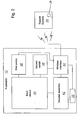
- FIGURE 2 is a wireless embodiment of surgical footswitch 10 of this invention having a progressive laser firing sequence.
- Input device 40 is analogous to the laser firing switch 20 of FIGURE 1 in its laser firing function, but has a progressive actuation functionality as described below. Futher, as in the other embodiments of the present invention, the embodiment of FIGURE 2 can also include a combination of switches and functions as described herein, and in particular the stand-by/ready switching functionality of the present invention.
- Input device 40 can be a pedal, other mechanical input device, or any other such device that can provide the progressive action as described herein and that will be familiar to those having skill in the art.
- laser firing switch 20 which can incorporate in one embodiment the functions of first switch 46 and second switch 48, ramps the laser 28 up to firing and then fires the laser 28 in the continuous movement of the surgeon's foot from initially depressing input device 40 (actuating first switch 46) to fully depressing input device 40 (actuating second switch 48).
- footswitch assembly 10 is illustrated in the embodiment of FIGURE 2 as establishing a wireless communication pathway between the footswitch assembly 10 and surgical laser 28, footswitch assembly 10 may instead be physically coupled to the control circuits associated with initializing and firing laser 28, such as by a cable assembly 24 of FIGURE 1 .
Landscapes
- Health & Medical Sciences (AREA)
- Ophthalmology & Optometry (AREA)
- Heart & Thoracic Surgery (AREA)
- Vascular Medicine (AREA)
- Optics & Photonics (AREA)
- Surgery (AREA)
- Engineering & Computer Science (AREA)
- Biomedical Technology (AREA)
- Physics & Mathematics (AREA)
- Nuclear Medicine, Radiotherapy & Molecular Imaging (AREA)
- Life Sciences & Earth Sciences (AREA)
- Animal Behavior & Ethology (AREA)
- General Health & Medical Sciences (AREA)
- Public Health (AREA)
- Veterinary Medicine (AREA)
- Laser Surgery Devices (AREA)
- Push-Button Switches (AREA)
- Switches With Compound Operations (AREA)
Claims (15)
- Chirurgie-Fußschalter (10) mit:einer Basis-Anordnung, wobei die Basis-Anordnung eine Absatzplatte (16) aufweist;einem Standby-/Betriebsbereit-Schalter (22), der an der Basis-Anordnung befestigt und betreibbar ist, um ein Standby-/Betriebsbereit-Steuersignal zum Schalten eines Lasers (28) zwischen einem Standby- und einem Betriebsbereit-Zustand zu erzeugen; undeinem Auslöse-Schalter (20, 48), der an der Basis-Anordnung befestigt und betreibbar ist, um ein Auslösesteuersignal zum Auslösen des Lasers zu erzeugen,dadurch gekennzeichnet, dass die Basis-Anordnung eine Ummantelung (14) aufweist, die so ausgeführt ist, dass sie den Auslöse-Schalter (20, 48) vor der Absatzplatte (16) abdeckt, und dass der Standby-/Betriebsbereit-Schalter (22) an einer Innenfläche der Ummantelung befestigt und so positioniert ist, dass er durch eine Bewegung des Fußes eines Betreibers zur Seite oder nach oben hin betätigt werden kann.
- Chirurgie-Fußschalter nach Anspruch 1, der des Weiteren eine Schnittstelle (23, 24, 50) aufweist, die in einer Kommunikationsverbindung mit dem Auslöse-Schalter (20) und dem Standby-/Betriebsbereit-Schalter (22) steht und betreibbar ist, um das Auslösesteuersignal und das Standby-/Betriebsbereit-Steuersignal an den Laser (28) weiterzuleiten.
- Chirurgie-Fußschalter nach Anspruch 2, wobei der Laser (28) betriebsmäßig mit einer Chirurgie-Konsole (26) verbunden ist, die so betreibbar ist, dass sie den Laser (28) steuert, und wobei die Schnittstelle (23, 24, 50) betreibbar ist, um den Chirurgie-Fußschalter kommunikativ mit der Chirurgie-Konsole zu werbinden und das Auslösesteuersignal und das Standby-/Betriebsbereit-Steuersignal an die Chirurgie-Konsole weiterzuleiten, wobei die Chirurgie-Konsole betreibbar ist, um den Laser auf der Grundlage des Auslösesteuersignals und des Standby-/Betriebsbereit-Steuersignals zu steuern.
- Chirurgie-Fußschalter nach Anspruch 3, wobei der Standby-/Betriebsbereit-Schalter (22) oberhalb des Fußes des Betreibers positioniert ist, so dass er durch eine Aufwärtsbewegung des Fußes des Betreibers betätigt werden kann, und wobei die Absatzplatte (16) so aufgebaut und angeordnet ist, dass sie sich unter dem Absatz des Betreibers befindet und betreibbar ist, um die Basis-Anordnung in Reaktion auf einen Druck des Absatzes des Betreibers nach unten mit einer Fläche unter der Basis-Anordnung in Kontakt zu halten.
- Chirurgie-Fußschalter nach Anspruch 4, der des Weiteren eine Hebesensor-Anordnung (30) aufweist, die betreibbar ist, um ein Anheben der Basis-Anordnung von der Oberfläche zu ermitteln und den Standby-/Betriebsbereit-Schalter (22) auf der Grundlage des ermittelten Anhebens zu desaktivieren.
- Chirurgie-Fußschalter nach Anspruch 5, wobei die Hebesensor-Anordnung (30) ausgewählt ist aus der Gruppe bestehend aus einem Ultraschall-Näherungssensor, einem optischen Sensor, einem Hochfrequenz-Signalmodulationssensor, einem Radarsensor, einem Drucksensor und einem Beschleunigungsmesser.
- Chirurgie-Fußschalter nach einem der Ansprüche 1 bis 6, der des Weiteren eine Fußsensor-Anordnung (36) aufweist, die betreibbar ist, um das Vorhandensein des Fußes eines Betreibers zu erkennen und in Reaktion auf das erkannte Vorhandensein des Fußes ein Steuersignal zu erzeugen.
- Chirurgie-Fußschalter nach Anspruch 7, wobei die Fußsensor-Anordnung (36) ausgewählt ist aus der Gruppe bestehend aus einem Ultraschall-Näherungssensor, einem optischen Sensor, einem Hochfrequenz-Signalmodulationssensor, einem Radarsensor, einem mechanischen Schaltgatter, einem optischen Lichtgatter und einem Beschleunigungsmesser.
- Chirurgie-Fußschalter nach Anspruch 7, wobei das Steuersignal an die Chirurgie-Konsole gesendet wird und im Betrieb veranlasst, dass sich der Laser (28) in Vorbereitung zum Auslösen aufwärmt.
- Chirurgie-Fußschalter nach einem der Ansprüche 1 bis 9, wobei die Schnittstelle eine drahtlose Schnittstelle (50) ist.
- Chirurgie-Fußschalter nach einem der Ansprüche 1 bis 9, wobei die Schnittstelle eine Leitungsanordnung (23, 24) aufweist.
- Chirurgie-Fußschalter nach Anspruch 1, der des Weiteren einen oder mehrere zusätzliche Schalter (22) aufweist, die betreibbar sind, um ein oder mehrere zusätzliche Steuersignale bereitzustellen, um im Betrieb eine oder mehrere Laser (28) -Funktionen zu steuern.
- Chirurgie-Fußschalter nach Anspruch 12, wobei die eine oder die mehreren Funktionen Laser (28) -Leistung und Impulsdauer umfassen.
- Chirurgie-Fußschalter nach einem der Ansprüche 1 bis 13, wobei die Ummantelung (14) und die Absatzplatte (16) eine integrierte Anordnung (12) sind.
- Chirurgie-Fußschalter nach Anspruch 14, wobei der Laser (28) ein Augenchirurgielaser ist.
Applications Claiming Priority (2)
| Application Number | Priority Date | Filing Date | Title |
|---|---|---|---|
| US69556105P | 2005-06-30 | 2005-06-30 | |
| PCT/US2006/025336 WO2007005507A2 (en) | 2005-06-30 | 2006-06-28 | Multifunction surgical footswitch |
Publications (3)
| Publication Number | Publication Date |
|---|---|
| EP1897105A2 EP1897105A2 (de) | 2008-03-12 |
| EP1897105A4 EP1897105A4 (de) | 2009-07-29 |
| EP1897105B1 true EP1897105B1 (de) | 2011-03-23 |
Family
ID=37604998
Family Applications (1)
| Application Number | Title | Priority Date | Filing Date |
|---|---|---|---|
| EP06785823A Active EP1897105B1 (de) | 2005-06-30 | 2006-06-28 | Chirurgischer multifunktionsfussschalter |
Country Status (10)
| Country | Link |
|---|---|
| US (1) | US7619171B2 (de) |
| EP (1) | EP1897105B1 (de) |
| JP (1) | JP2009500076A (de) |
| AT (1) | ATE503260T1 (de) |
| AU (1) | AU2006266001C1 (de) |
| CA (1) | CA2612139C (de) |
| DE (1) | DE602006020872D1 (de) |
| ES (1) | ES2361854T3 (de) |
| TW (1) | TWI367515B (de) |
| WO (1) | WO2007005507A2 (de) |
Families Citing this family (55)
| Publication number | Priority date | Publication date | Assignee | Title |
|---|---|---|---|---|
| JP2006527055A (ja) * | 2003-06-11 | 2006-11-30 | コーニンクレッカ フィリップス エレクトロニクス エヌ ヴィ | ハンドル内に制御機構を含む内部撮像のための超音波システム |
| CA2803828C (en) * | 2005-03-31 | 2015-11-24 | Alcon, Inc. | Footswitch operable to control a surgical system |
| DE102006024108B4 (de) * | 2006-05-19 | 2021-01-21 | Carl Zeiss Meditec Ag | Anordnung zum Beeinflussen von Gerätefunktionen durch Fußbewegung |
| US8465473B2 (en) | 2007-03-28 | 2013-06-18 | Novartis Ag | Surgical footswitch with movable shroud |
| DE102007014785B4 (de) * | 2007-03-28 | 2009-07-09 | Sirona Dental Systems Gmbh | Fußsteuereinrichtung |
| DE102007018811B4 (de) | 2007-04-20 | 2009-07-09 | Siemens Ag | Vorrichtung mit einem beweglichen Patiententisch und/oder Deckenstativ und Verfahren zum Ermöglichen des Bewegens eines beweglichen Patiententischs und /oder Deckenstativs nur durch eine berechtigte Bedienperson |
| US20090005789A1 (en) * | 2007-06-26 | 2009-01-01 | Charles Steven T | Force Sensitive Foot Controller |
| DE102007042389A1 (de) | 2007-09-04 | 2009-03-05 | Carl Zeiss Surgical Gmbh | Verfahren zum Anmelden von kabellosen elektrischen Stelleinrichtungen an einem medizinischen Gerät |
| US8409182B2 (en) | 2007-09-28 | 2013-04-02 | Eos Holdings, Llc | Laser-assisted thermal separation of tissue |
| WO2010030788A2 (en) * | 2008-09-10 | 2010-03-18 | Mora Assad F | Foot actuated switch |
| US8937561B2 (en) | 2008-11-17 | 2015-01-20 | Canyon Ridge Resources, L.L.C. | System and method for control of medical equipment using multiple wireless devices |
| US8159370B2 (en) * | 2008-11-17 | 2012-04-17 | Canyon Ridge Resources, Llc | System and method for control of medical equipment using multiple wireless devices |
| US8274376B2 (en) * | 2008-11-17 | 2012-09-25 | Canyon Ridge Resources, L.L.C. | System and method for wireless control of medical devices |
| US9655639B2 (en) | 2008-12-16 | 2017-05-23 | Nico Corporation | Tissue removal device for use with imaging devices in neurosurgical and spinal surgery applications |
| US9931105B2 (en) | 2008-12-16 | 2018-04-03 | Nico Corporation | System and method of taking and collecting tissue cores for treatment |
| US8460327B2 (en) | 2008-12-16 | 2013-06-11 | Nico Corporation | Tissue removal device for neurosurgical and spinal surgery applications |
| US8496599B2 (en) | 2008-12-16 | 2013-07-30 | Nico Corporation | Tissue removal device for neurosurgical and spinal surgery applications |
| US9279751B2 (en) | 2008-12-16 | 2016-03-08 | Nico Corporation | System and method of taking and collecting tissue cores for treatment |
| US9820480B2 (en) | 2008-12-16 | 2017-11-21 | Nico Corporation | System for collecting and preserving tissue cores |
| US8357175B2 (en) | 2008-12-16 | 2013-01-22 | Nico Corporation | Positioning system for tissue removal device |
| US10368890B2 (en) | 2008-12-16 | 2019-08-06 | Nico Corporation | Multi-functional surgical device for neurosurgical and spinal surgery applications |
| US8430825B2 (en) | 2008-12-16 | 2013-04-30 | Nico Corporation | Tissue removal device for neurosurgical and spinal surgery applications |
| US9216031B2 (en) | 2008-12-16 | 2015-12-22 | Nico Corporation | Tissue removal device with adjustable fluid supply sleeve for neurosurgical and spinal surgery applications |
| US20100152762A1 (en) * | 2008-12-16 | 2010-06-17 | Mark Joseph L | Tissue removal system with multi-directional foot actuator assembly for neurosurgical and spinal surgery applications |
| US8702738B2 (en) | 2008-12-16 | 2014-04-22 | Nico Corporation | Tissue removal device for neurosurgical and spinal surgery applications |
| US10080578B2 (en) | 2008-12-16 | 2018-09-25 | Nico Corporation | Tissue removal device with adjustable delivery sleeve for neurosurgical and spinal surgery applications |
| US8657841B2 (en) | 2008-12-16 | 2014-02-25 | Nico Corporation | Tissue removal device for neurosurgical and spinal surgery applications |
| US20100198200A1 (en) * | 2009-01-30 | 2010-08-05 | Christopher Horvath | Smart Illumination for Surgical Devices |
| DE102010000642B4 (de) | 2009-03-12 | 2015-05-07 | Erbe Elektromedizin Gmbh | Schaltsteuereinrichtung und Handhabungsteil eines medizinischen Instruments |
| US8882803B2 (en) * | 2009-04-01 | 2014-11-11 | Globus Medical, Inc. | Orthopedic clamp and extension rod |
| NO329473B1 (no) * | 2009-04-01 | 2010-10-25 | Trenmentor Jan Wiese | Fotbetjent styringsanordning |
| US8888149B2 (en) * | 2010-11-15 | 2014-11-18 | Robert Joshua Lehr | Sanitary door latch system |
| US20120199150A1 (en) * | 2011-02-09 | 2012-08-09 | Minh Le | Apparatus And Method For Attaching And/Or Repairing Fake Nails |
| ES2577012T3 (es) | 2011-03-25 | 2016-07-12 | Eos Holdings, Llc | Láser médico con obturador electrónico |
| US9240110B2 (en) | 2011-10-20 | 2016-01-19 | Alcon Research, Ltd. | Haptic footswitch treadle |
| US10420882B2 (en) | 2013-03-15 | 2019-09-24 | Medovate Limited | Method and system for controllably administering fluid to a patient and/or for controllably withdrawing fluid from the patient |
| US9820886B2 (en) * | 2014-02-28 | 2017-11-21 | Excel-Lens, Inc. | Laser assisted cataract surgery |
| CA2940307C (en) * | 2014-02-28 | 2022-07-12 | Excel-Lens, Inc. | Laser assisted cataract surgery |
| US10231872B2 (en) * | 2014-02-28 | 2019-03-19 | Excel-Lens, Inc. | Laser assisted cataract surgery |
| US20150245945A1 (en) * | 2014-02-28 | 2015-09-03 | David Mordaunt | Laser assisted cataract surgery |
| US10327951B2 (en) | 2014-02-28 | 2019-06-25 | Excel-Lens, Inc. | Laser assisted cataract surgery |
| US10206817B2 (en) * | 2014-02-28 | 2019-02-19 | Excel-Lens, Inc. | Laser assisted cataract surgery |
| US10864054B2 (en) * | 2016-11-17 | 2020-12-15 | Alcon Inc. | Tri-axial ergonomic footswitch |
| WO2018092005A2 (en) | 2016-11-17 | 2018-05-24 | Novartis Ag | Ergonomic foot-operated joystick |
| DE102017113393A1 (de) * | 2017-06-19 | 2018-12-20 | Fresenius Medical Care Deutschland Gmbh | Steuervorrichtung für Blutbehandlungsvorrichtung und Blutbehandlungsvorrichtung |
| AU2018347507B2 (en) * | 2017-10-13 | 2024-01-25 | Boston Scientific Scimed, Inc. | Medical systems, devices, and related methods |
| CN107837463B (zh) * | 2017-10-31 | 2024-01-12 | 重庆京渝激光技术有限公司 | 带脚踏开关收纳功能的激光治疗仪 |
| EP3823572B1 (de) * | 2018-08-21 | 2023-09-20 | Alcon Inc. | Multifunktionaler chirurgischer fussschalter mit integrierter abschirmung |
| US10925680B2 (en) | 2018-09-18 | 2021-02-23 | Alcon Inc. | Foot controller with adjustable treadle |
| US12114846B2 (en) | 2018-10-29 | 2024-10-15 | Stryker Corporation | Systems and methods of performing spine surgery and maintaining a volume of fluid at a surgical site |
| DE102019204287A1 (de) | 2019-03-27 | 2020-10-01 | Siemens Healthcare Gmbh | Vorrichtung und Verfahren zur Kontrolle von Akquisitionsparametern bei der Durchführung einer medizinischen Röntgenuntersuchung |
| US11740648B2 (en) | 2019-08-01 | 2023-08-29 | Alcon Inc. | Surgical footswitch having elevated auxiliary buttons |
| US11464565B2 (en) | 2019-11-13 | 2022-10-11 | Alcon Inc. | Electronic shroud for laser emission control |
| CN114404049B (zh) * | 2022-01-26 | 2024-12-27 | 合肥工业大学 | 一种飞秒激光手术机器人控制系统及方法 |
| US20230363945A1 (en) * | 2022-05-10 | 2023-11-16 | Alcon Inc. | Laser pulse control with sub-carrier modulation |
Family Cites Families (31)
| Publication number | Priority date | Publication date | Assignee | Title |
|---|---|---|---|---|
| US4837857A (en) * | 1986-11-06 | 1989-06-06 | Storz Instrument Company | Foot pedal assembly for ophthalmic surgical instrument |
| US4965417A (en) * | 1989-03-27 | 1990-10-23 | Massie Philip E | Foot-operated control |
| US4983901A (en) * | 1989-04-21 | 1991-01-08 | Allergan, Inc. | Digital electronic foot control for medical apparatus and the like |
| US5091656A (en) * | 1989-10-27 | 1992-02-25 | Storz Instrument Company | Footswitch assembly with electrically engaged detents |
| US5180925A (en) * | 1991-02-22 | 1993-01-19 | Outboard Marine Corporation | Remote switching system for an electric trolling motor |
| EP0596967A4 (de) * | 1991-07-31 | 1994-10-19 | Mentor O & O Inc | Bedienungssteuerung von handstücken während einer chirurgischen augenbehandlung. |
| US5214360A (en) * | 1992-03-13 | 1993-05-25 | Den-Tal-Ez, Inc. | Programmable adjustable chair for medical and dental applications |
| US5268624A (en) * | 1992-10-14 | 1993-12-07 | Allergan, Inc. | Foot pedal control with user-selectable operational ranges |
| US5787760A (en) * | 1993-11-24 | 1998-08-04 | Thorlakson; Richard G. | Method and foot pedal apparatus for operating a microscope |
| US5554894A (en) * | 1994-10-28 | 1996-09-10 | Iolab Corporation | Electronic footswitch for ophthalmic surgery |
| US5635777A (en) * | 1995-12-28 | 1997-06-03 | Andrew Telymonde | Foot operated control apparatus |
| AU724661B2 (en) | 1996-08-29 | 2000-09-28 | Bausch & Lomb Surgical, Inc. | Dual loop frequency and power control |
| US6039565A (en) * | 1997-01-14 | 2000-03-21 | Chou; Marilyn M. | Combined ultrasonic and laser device and method of use |
| US6179829B1 (en) * | 1997-08-28 | 2001-01-30 | Bausch & Lomb Surgical, Inc. | Foot controller for microsurgical system |
| US5983749A (en) * | 1997-09-12 | 1999-11-16 | Allergan Sales, Inc. | Dual position foot pedal for ophthalmic surgery apparatus |
| US6150623A (en) | 1998-08-27 | 2000-11-21 | Allergan | Back-flip medical footpedal |
| JP2001095817A (ja) * | 1999-09-30 | 2001-04-10 | Nidek Co Ltd | レーザ治療装置 |
| DE20105851U1 (de) * | 2000-04-12 | 2001-10-11 | Nakoinz, Bärbel, 68535 Edingen-Neckarhausen | Fußschalter |
| US6452123B1 (en) | 2000-06-27 | 2002-09-17 | Advanced Medical Optics | Surgical foot pedal control including ribbon switch arrangement |
| US7012203B2 (en) * | 2001-09-07 | 2006-03-14 | Carl Zeiss Surgical Gmbh | Foot switch pedal controller for a surgical instrument |
| US6689975B2 (en) * | 2001-12-19 | 2004-02-10 | Bausch & Lomb Incorporated | Foot controller including multiple switch arrangement with heel operated, door-type switch actuator |
| US6639332B2 (en) * | 2001-12-19 | 2003-10-28 | Bausch & Lomb Incorporated | Foot controller with ophthalmic surgery interlock circuit and method |
| WO2003105169A1 (en) * | 2002-06-11 | 2003-12-18 | Tyco Healthcare Group, Lp | Illuminated foot-switch |
| US7422432B2 (en) * | 2002-06-17 | 2008-09-09 | Warner Systems, Llc | System and method for remotely controlling devices |
| US7193169B2 (en) * | 2003-10-29 | 2007-03-20 | Alcon, Inc. | Ergonomic footswitch |
| US7019234B1 (en) * | 2003-11-13 | 2006-03-28 | Alcon, Inc. | Footswitch |
| US7084364B2 (en) * | 2003-11-13 | 2006-08-01 | Alcon, Inc. | Dual control footswitch assembly |
| CA2803828C (en) * | 2005-03-31 | 2015-11-24 | Alcon, Inc. | Footswitch operable to control a surgical system |
| US7323646B2 (en) * | 2005-04-14 | 2008-01-29 | Conntrol International, Inc. | Hand and foot switch |
| US7439463B2 (en) * | 2006-01-17 | 2008-10-21 | Dentsply International Inc. | Foot switch for activating a dental or medical treatment apparatus |
| US7381917B2 (en) * | 2006-09-20 | 2008-06-03 | Alcon, Inc. | Footswitch assembly with position memory |
-
2006
- 2006-06-26 US US11/474,668 patent/US7619171B2/en active Active
- 2006-06-28 EP EP06785823A patent/EP1897105B1/de active Active
- 2006-06-28 ES ES06785823T patent/ES2361854T3/es active Active
- 2006-06-28 CA CA2612139A patent/CA2612139C/en active Active
- 2006-06-28 DE DE602006020872T patent/DE602006020872D1/de active Active
- 2006-06-28 JP JP2008519562A patent/JP2009500076A/ja not_active Withdrawn
- 2006-06-28 AU AU2006266001A patent/AU2006266001C1/en active Active
- 2006-06-28 AT AT06785823T patent/ATE503260T1/de not_active IP Right Cessation
- 2006-06-28 WO PCT/US2006/025336 patent/WO2007005507A2/en not_active Ceased
- 2006-06-29 TW TW095123616A patent/TWI367515B/zh not_active IP Right Cessation
Also Published As
| Publication number | Publication date |
|---|---|
| TW200723331A (en) | 2007-06-16 |
| US20070043339A1 (en) | 2007-02-22 |
| EP1897105A2 (de) | 2008-03-12 |
| JP2009500076A (ja) | 2009-01-08 |
| ATE503260T1 (de) | 2011-04-15 |
| US7619171B2 (en) | 2009-11-17 |
| DE602006020872D1 (de) | 2011-05-05 |
| WO2007005507A2 (en) | 2007-01-11 |
| CA2612139C (en) | 2014-06-10 |
| AU2006266001A1 (en) | 2007-01-11 |
| WO2007005507A9 (en) | 2007-03-08 |
| ES2361854T3 (es) | 2011-06-22 |
| EP1897105A4 (de) | 2009-07-29 |
| WO2007005507A3 (en) | 2007-04-19 |
| AU2006266001B2 (en) | 2010-06-17 |
| AU2006266001C1 (en) | 2010-11-18 |
| TWI367515B (en) | 2012-07-01 |
| CA2612139A1 (en) | 2007-01-11 |
Similar Documents
| Publication | Publication Date | Title |
|---|---|---|
| CA2612139C (en) | Multifunction surgical footswitch | |
| EP1872753A1 (de) | Multifunktionelle chirurgische Sonde | |
| EP0789929B1 (de) | Elektronischer fussschalter für ophthalmologische chirurgie | |
| EP1477125B1 (de) | System zur Aktivierung eines elektrochirurgischen Instruments | |
| US20100198200A1 (en) | Smart Illumination for Surgical Devices | |
| CN1273097C (zh) | 脚踏控制器 | |
| EP1912533B1 (de) | Verbessertes fusskontrolpedal | |
| JP4224550B2 (ja) | インターロック回路を有するフットコントローラー | |
| WO1996013845A9 (en) | Electronic footswitch for ophthalmic surgery | |
| EP1707146A2 (de) | System zur Aktivierung eines elektrochirurgischen Instruments |
Legal Events
| Date | Code | Title | Description |
|---|---|---|---|
| PUAI | Public reference made under article 153(3) epc to a published international application that has entered the european phase |
Free format text: ORIGINAL CODE: 0009012 |
|
| 17P | Request for examination filed |
Effective date: 20071212 |
|
| AK | Designated contracting states |
Kind code of ref document: A2 Designated state(s): AT BE BG CH CY CZ DE DK EE ES FI FR GB GR HU IE IS IT LI LT LU LV MC NL PL PT RO SE SI SK TR |
|
| DAX | Request for extension of the european patent (deleted) | ||
| DAX | Request for extension of the european patent (deleted) | ||
| A4 | Supplementary search report drawn up and despatched |
Effective date: 20090629 |
|
| RAP1 | Party data changed (applicant data changed or rights of an application transferred) |
Owner name: ALCON, INC. |
|
| 17Q | First examination report despatched |
Effective date: 20090717 |
|
| GRAP | Despatch of communication of intention to grant a patent |
Free format text: ORIGINAL CODE: EPIDOSNIGR1 |
|
| GRAS | Grant fee paid |
Free format text: ORIGINAL CODE: EPIDOSNIGR3 |
|
| GRAA | (expected) grant |
Free format text: ORIGINAL CODE: 0009210 |
|
| AK | Designated contracting states |
Kind code of ref document: B1 Designated state(s): AT BE BG CH CY CZ DE DK EE ES FI FR GB GR HU IE IS IT LI LT LU LV MC NL PL PT RO SE SI SK TR |
|
| REG | Reference to a national code |
Ref country code: GB Ref legal event code: FG4D |
|
| REG | Reference to a national code |
Ref country code: CH Ref legal event code: EP |
|
| REG | Reference to a national code |
Ref country code: IE Ref legal event code: FG4D |
|
| REG | Reference to a national code |
Ref country code: CH Ref legal event code: NV Representative=s name: LEMAN CONSULTING S.A. |
|
| REF | Corresponds to: |
Ref document number: 602006020872 Country of ref document: DE Date of ref document: 20110505 Kind code of ref document: P |
|
| REG | Reference to a national code |
Ref country code: DE Ref legal event code: R096 Ref document number: 602006020872 Country of ref document: DE Effective date: 20110505 |
|
| REG | Reference to a national code |
Ref country code: ES Ref legal event code: FG2A Ref document number: 2361854 Country of ref document: ES Kind code of ref document: T3 Effective date: 20110622 Ref country code: NL Ref legal event code: T3 |
|
| PG25 | Lapsed in a contracting state [announced via postgrant information from national office to epo] |
Ref country code: GR Free format text: LAPSE BECAUSE OF FAILURE TO SUBMIT A TRANSLATION OF THE DESCRIPTION OR TO PAY THE FEE WITHIN THE PRESCRIBED TIME-LIMIT Effective date: 20110624 Ref country code: LV Free format text: LAPSE BECAUSE OF FAILURE TO SUBMIT A TRANSLATION OF THE DESCRIPTION OR TO PAY THE FEE WITHIN THE PRESCRIBED TIME-LIMIT Effective date: 20110323 Ref country code: LT Free format text: LAPSE BECAUSE OF FAILURE TO SUBMIT A TRANSLATION OF THE DESCRIPTION OR TO PAY THE FEE WITHIN THE PRESCRIBED TIME-LIMIT Effective date: 20110323 Ref country code: SE Free format text: LAPSE BECAUSE OF FAILURE TO SUBMIT A TRANSLATION OF THE DESCRIPTION OR TO PAY THE FEE WITHIN THE PRESCRIBED TIME-LIMIT Effective date: 20110323 |
|
| LTIE | Lt: invalidation of european patent or patent extension |
Effective date: 20110323 |
|
| PG25 | Lapsed in a contracting state [announced via postgrant information from national office to epo] |
Ref country code: SI Free format text: LAPSE BECAUSE OF FAILURE TO SUBMIT A TRANSLATION OF THE DESCRIPTION OR TO PAY THE FEE WITHIN THE PRESCRIBED TIME-LIMIT Effective date: 20110323 Ref country code: AT Free format text: LAPSE BECAUSE OF FAILURE TO SUBMIT A TRANSLATION OF THE DESCRIPTION OR TO PAY THE FEE WITHIN THE PRESCRIBED TIME-LIMIT Effective date: 20110323 Ref country code: FI Free format text: LAPSE BECAUSE OF FAILURE TO SUBMIT A TRANSLATION OF THE DESCRIPTION OR TO PAY THE FEE WITHIN THE PRESCRIBED TIME-LIMIT Effective date: 20110323 Ref country code: BG Free format text: LAPSE BECAUSE OF FAILURE TO SUBMIT A TRANSLATION OF THE DESCRIPTION OR TO PAY THE FEE WITHIN THE PRESCRIBED TIME-LIMIT Effective date: 20110623 Ref country code: CY Free format text: LAPSE BECAUSE OF FAILURE TO SUBMIT A TRANSLATION OF THE DESCRIPTION OR TO PAY THE FEE WITHIN THE PRESCRIBED TIME-LIMIT Effective date: 20110323 |
|
| PG25 | Lapsed in a contracting state [announced via postgrant information from national office to epo] |
Ref country code: BE Free format text: LAPSE BECAUSE OF FAILURE TO SUBMIT A TRANSLATION OF THE DESCRIPTION OR TO PAY THE FEE WITHIN THE PRESCRIBED TIME-LIMIT Effective date: 20110323 |
|
| PG25 | Lapsed in a contracting state [announced via postgrant information from national office to epo] |
Ref country code: EE Free format text: LAPSE BECAUSE OF FAILURE TO SUBMIT A TRANSLATION OF THE DESCRIPTION OR TO PAY THE FEE WITHIN THE PRESCRIBED TIME-LIMIT Effective date: 20110323 Ref country code: PT Free format text: LAPSE BECAUSE OF FAILURE TO SUBMIT A TRANSLATION OF THE DESCRIPTION OR TO PAY THE FEE WITHIN THE PRESCRIBED TIME-LIMIT Effective date: 20110725 |
|
| PG25 | Lapsed in a contracting state [announced via postgrant information from national office to epo] |
Ref country code: CZ Free format text: LAPSE BECAUSE OF FAILURE TO SUBMIT A TRANSLATION OF THE DESCRIPTION OR TO PAY THE FEE WITHIN THE PRESCRIBED TIME-LIMIT Effective date: 20110323 Ref country code: IS Free format text: LAPSE BECAUSE OF FAILURE TO SUBMIT A TRANSLATION OF THE DESCRIPTION OR TO PAY THE FEE WITHIN THE PRESCRIBED TIME-LIMIT Effective date: 20110723 Ref country code: SK Free format text: LAPSE BECAUSE OF FAILURE TO SUBMIT A TRANSLATION OF THE DESCRIPTION OR TO PAY THE FEE WITHIN THE PRESCRIBED TIME-LIMIT Effective date: 20110323 Ref country code: RO Free format text: LAPSE BECAUSE OF FAILURE TO SUBMIT A TRANSLATION OF THE DESCRIPTION OR TO PAY THE FEE WITHIN THE PRESCRIBED TIME-LIMIT Effective date: 20110323 |
|
| PLBE | No opposition filed within time limit |
Free format text: ORIGINAL CODE: 0009261 |
|
| STAA | Information on the status of an ep patent application or granted ep patent |
Free format text: STATUS: NO OPPOSITION FILED WITHIN TIME LIMIT |
|
| 26N | No opposition filed |
Effective date: 20111227 |
|
| PG25 | Lapsed in a contracting state [announced via postgrant information from national office to epo] |
Ref country code: PL Free format text: LAPSE BECAUSE OF FAILURE TO SUBMIT A TRANSLATION OF THE DESCRIPTION OR TO PAY THE FEE WITHIN THE PRESCRIBED TIME-LIMIT Effective date: 20110323 Ref country code: DK Free format text: LAPSE BECAUSE OF FAILURE TO SUBMIT A TRANSLATION OF THE DESCRIPTION OR TO PAY THE FEE WITHIN THE PRESCRIBED TIME-LIMIT Effective date: 20110323 |
|
| REG | Reference to a national code |
Ref country code: IE Ref legal event code: MM4A |
|
| REG | Reference to a national code |
Ref country code: DE Ref legal event code: R097 Ref document number: 602006020872 Country of ref document: DE Effective date: 20111227 |
|
| PG25 | Lapsed in a contracting state [announced via postgrant information from national office to epo] |
Ref country code: IE Free format text: LAPSE BECAUSE OF NON-PAYMENT OF DUE FEES Effective date: 20110628 |
|
| PG25 | Lapsed in a contracting state [announced via postgrant information from national office to epo] |
Ref country code: MC Free format text: LAPSE BECAUSE OF NON-PAYMENT OF DUE FEES Effective date: 20110630 |
|
| PG25 | Lapsed in a contracting state [announced via postgrant information from national office to epo] |
Ref country code: LU Free format text: LAPSE BECAUSE OF NON-PAYMENT OF DUE FEES Effective date: 20110628 |
|
| PG25 | Lapsed in a contracting state [announced via postgrant information from national office to epo] |
Ref country code: TR Free format text: LAPSE BECAUSE OF FAILURE TO SUBMIT A TRANSLATION OF THE DESCRIPTION OR TO PAY THE FEE WITHIN THE PRESCRIBED TIME-LIMIT Effective date: 20110323 |
|
| PG25 | Lapsed in a contracting state [announced via postgrant information from national office to epo] |
Ref country code: HU Free format text: LAPSE BECAUSE OF FAILURE TO SUBMIT A TRANSLATION OF THE DESCRIPTION OR TO PAY THE FEE WITHIN THE PRESCRIBED TIME-LIMIT Effective date: 20110323 |
|
| REG | Reference to a national code |
Ref country code: FR Ref legal event code: PLFP Year of fee payment: 10 |
|
| REG | Reference to a national code |
Ref country code: FR Ref legal event code: PLFP Year of fee payment: 11 |
|
| REG | Reference to a national code |
Ref country code: FR Ref legal event code: PLFP Year of fee payment: 12 |
|
| REG | Reference to a national code |
Ref country code: CH Ref legal event code: NV Representative=s name: IP PARTNERS J. WENGER, CH |
|
| REG | Reference to a national code |
Ref country code: FR Ref legal event code: PLFP Year of fee payment: 13 |
|
| PGFP | Annual fee paid to national office [announced via postgrant information from national office to epo] |
Ref country code: NL Payment date: 20190612 Year of fee payment: 14 |
|
| PGFP | Annual fee paid to national office [announced via postgrant information from national office to epo] |
Ref country code: CH Payment date: 20190614 Year of fee payment: 14 |
|
| REG | Reference to a national code |
Ref country code: NL Ref legal event code: PD Owner name: ALCON INC.; CH Free format text: DETAILS ASSIGNMENT: CHANGE OF OWNER(S), MERGE; FORMER OWNER NAME: NOVARTIS AG Effective date: 20191031 |
|
| REG | Reference to a national code |
Ref country code: CH Ref legal event code: PUE Owner name: ALCON INC., CH Free format text: FORMER OWNER: ALCON, INC., CH |
|
| REG | Reference to a national code |
Ref country code: GB Ref legal event code: 732E Free format text: REGISTERED BETWEEN 20200109 AND 20200115 |
|
| REG | Reference to a national code |
Ref country code: GB Ref legal event code: 732E Free format text: REGISTERED BETWEEN 20200116 AND 20200122 |
|
| REG | Reference to a national code |
Ref country code: DE Ref legal event code: R082 Ref document number: 602006020872 Country of ref document: DE Representative=s name: MEISSNER BOLTE PATENTANWAELTE RECHTSANWAELTE P, DE Ref country code: DE Ref legal event code: R081 Ref document number: 602006020872 Country of ref document: DE Owner name: ALCON INC., CH Free format text: FORMER OWNER: ALCON INC., HUENENBERG, CH |
|
| REG | Reference to a national code |
Ref country code: ES Ref legal event code: PC2A Owner name: ALCON INC. Effective date: 20200331 |
|
| REG | Reference to a national code |
Ref country code: CH Ref legal event code: PL |
|
| REG | Reference to a national code |
Ref country code: NL Ref legal event code: MM Effective date: 20200701 |
|
| PG25 | Lapsed in a contracting state [announced via postgrant information from national office to epo] |
Ref country code: LI Free format text: LAPSE BECAUSE OF NON-PAYMENT OF DUE FEES Effective date: 20200630 Ref country code: CH Free format text: LAPSE BECAUSE OF NON-PAYMENT OF DUE FEES Effective date: 20200630 Ref country code: NL Free format text: LAPSE BECAUSE OF NON-PAYMENT OF DUE FEES Effective date: 20200701 |
|
| P01 | Opt-out of the competence of the unified patent court (upc) registered |
Effective date: 20230504 |
|
| PGFP | Annual fee paid to national office [announced via postgrant information from national office to epo] |
Ref country code: DE Payment date: 20250521 Year of fee payment: 20 |
|
| PGFP | Annual fee paid to national office [announced via postgrant information from national office to epo] |
Ref country code: GB Payment date: 20250522 Year of fee payment: 20 |
|
| PGFP | Annual fee paid to national office [announced via postgrant information from national office to epo] |
Ref country code: IT Payment date: 20250528 Year of fee payment: 20 |
|
| PGFP | Annual fee paid to national office [announced via postgrant information from national office to epo] |
Ref country code: FR Payment date: 20250523 Year of fee payment: 20 |
|
| PGFP | Annual fee paid to national office [announced via postgrant information from national office to epo] |
Ref country code: ES Payment date: 20250703 Year of fee payment: 20 |