EP1897486A1 - Dispositif de surveillance optique de substances sanguines à analyser - Google Patents
Dispositif de surveillance optique de substances sanguines à analyser Download PDFInfo
- Publication number
- EP1897486A1 EP1897486A1 EP06120413A EP06120413A EP1897486A1 EP 1897486 A1 EP1897486 A1 EP 1897486A1 EP 06120413 A EP06120413 A EP 06120413A EP 06120413 A EP06120413 A EP 06120413A EP 1897486 A1 EP1897486 A1 EP 1897486A1
- Authority
- EP
- European Patent Office
- Prior art keywords
- light
- monitor
- filter
- filters
- optical
- Prior art date
- Legal status (The legal status is an assumption and is not a legal conclusion. Google has not performed a legal analysis and makes no representation as to the accuracy of the status listed.)
- Withdrawn
Links
Images


Classifications
-
- G—PHYSICS
- G01—MEASURING; TESTING
- G01N—INVESTIGATING OR ANALYSING MATERIALS BY DETERMINING THEIR CHEMICAL OR PHYSICAL PROPERTIES
- G01N21/00—Investigating or analysing materials by the use of optical means, i.e. using sub-millimetre waves, infrared, visible or ultraviolet light
- G01N21/17—Systems in which incident light is modified in accordance with the properties of the material investigated
- G01N21/25—Colour; Spectral properties, i.e. comparison of effect of material on the light at two or more different wavelengths or wavelength bands
- G01N21/31—Investigating relative effect of material at wavelengths characteristic of specific elements or molecules, e.g. atomic absorption spectrometry
- G01N21/35—Investigating relative effect of material at wavelengths characteristic of specific elements or molecules, e.g. atomic absorption spectrometry using infrared light
- G01N21/359—Investigating relative effect of material at wavelengths characteristic of specific elements or molecules, e.g. atomic absorption spectrometry using infrared light using near infrared light
-
- A—HUMAN NECESSITIES
- A61—MEDICAL OR VETERINARY SCIENCE; HYGIENE
- A61B—DIAGNOSIS; SURGERY; IDENTIFICATION
- A61B5/00—Measuring for diagnostic purposes; Identification of persons
- A61B5/145—Measuring characteristics of blood in vivo, e.g. gas concentration or pH-value ; Measuring characteristics of body fluids or tissues, e.g. interstitial fluid or cerebral tissue
- A61B5/14532—Measuring characteristics of blood in vivo, e.g. gas concentration or pH-value ; Measuring characteristics of body fluids or tissues, e.g. interstitial fluid or cerebral tissue for measuring glucose, e.g. by tissue impedance measurement
-
- A—HUMAN NECESSITIES
- A61—MEDICAL OR VETERINARY SCIENCE; HYGIENE
- A61B—DIAGNOSIS; SURGERY; IDENTIFICATION
- A61B5/00—Measuring for diagnostic purposes; Identification of persons
- A61B5/145—Measuring characteristics of blood in vivo, e.g. gas concentration or pH-value ; Measuring characteristics of body fluids or tissues, e.g. interstitial fluid or cerebral tissue
- A61B5/1455—Measuring characteristics of blood in vivo, e.g. gas concentration or pH-value ; Measuring characteristics of body fluids or tissues, e.g. interstitial fluid or cerebral tissue using optical sensors, e.g. spectral photometrical oximeters
-
- A—HUMAN NECESSITIES
- A61—MEDICAL OR VETERINARY SCIENCE; HYGIENE
- A61B—DIAGNOSIS; SURGERY; IDENTIFICATION
- A61B5/00—Measuring for diagnostic purposes; Identification of persons
- A61B5/145—Measuring characteristics of blood in vivo, e.g. gas concentration or pH-value ; Measuring characteristics of body fluids or tissues, e.g. interstitial fluid or cerebral tissue
- A61B5/1495—Calibrating or testing of in-vivo probes
-
- G—PHYSICS
- G01—MEASURING; TESTING
- G01N—INVESTIGATING OR ANALYSING MATERIALS BY DETERMINING THEIR CHEMICAL OR PHYSICAL PROPERTIES
- G01N21/00—Investigating or analysing materials by the use of optical means, i.e. using sub-millimetre waves, infrared, visible or ultraviolet light
- G01N21/17—Systems in which incident light is modified in accordance with the properties of the material investigated
- G01N21/25—Colour; Spectral properties, i.e. comparison of effect of material on the light at two or more different wavelengths or wavelength bands
- G01N21/31—Investigating relative effect of material at wavelengths characteristic of specific elements or molecules, e.g. atomic absorption spectrometry
- G01N2021/3129—Determining multicomponents by multiwavelength light
- G01N2021/3133—Determining multicomponents by multiwavelength light with selection of wavelengths before the sample
-
- G—PHYSICS
- G01—MEASURING; TESTING
- G01N—INVESTIGATING OR ANALYSING MATERIALS BY DETERMINING THEIR CHEMICAL OR PHYSICAL PROPERTIES
- G01N21/00—Investigating or analysing materials by the use of optical means, i.e. using sub-millimetre waves, infrared, visible or ultraviolet light
- G01N21/17—Systems in which incident light is modified in accordance with the properties of the material investigated
- G01N21/25—Colour; Spectral properties, i.e. comparison of effect of material on the light at two or more different wavelengths or wavelength bands
- G01N21/31—Investigating relative effect of material at wavelengths characteristic of specific elements or molecules, e.g. atomic absorption spectrometry
- G01N21/314—Investigating relative effect of material at wavelengths characteristic of specific elements or molecules, e.g. atomic absorption spectrometry with comparison of measurements at specific and non-specific wavelengths
- G01N2021/317—Special constructive features
- G01N2021/3177—Use of spatially separated filters in simultaneous way
-
- G—PHYSICS
- G01—MEASURING; TESTING
- G01N—INVESTIGATING OR ANALYSING MATERIALS BY DETERMINING THEIR CHEMICAL OR PHYSICAL PROPERTIES
- G01N2201/00—Features of devices classified in G01N21/00
- G01N2201/06—Illumination; Optics
- G01N2201/062—LED's
- G01N2201/0627—Use of several LED's for spectral resolution
-
- G—PHYSICS
- G01—MEASURING; TESTING
- G01N—INVESTIGATING OR ANALYSING MATERIALS BY DETERMINING THEIR CHEMICAL OR PHYSICAL PROPERTIES
- G01N2201/00—Features of devices classified in G01N21/00
- G01N2201/12—Circuits of general importance; Signal processing
- G01N2201/129—Using chemometrical methods
Definitions
- the present invention relates to an optical blood analyte monitor and in particular to a non-invasive blood glucose monitor.
- optical methods and apparatus rely on the detection of the magnitude of light attenuation caused by the absorption fingerprint of blood glucose as represented in the targeted tissue volume. It is known, from for example US 5,529,755 of Higashio et al. , to employ optical radiation in one or more of the wavelength bands centered around 1575 nm, 1765nm, 21 00nm and 2270 nm or a broad band between 1560 nm and 1760 nm or between 2080nm and 2230nm in order to detect characteristic absorption by blood glucose.
- the signal due to the absorption of glucose is extracted from the spectral measurement using one or more mathematical (chemometric) models.
- the models are developed through the process of calibration on the basis of a calibration set of spectral measurements and associated known reference blood glucose values typically obtained using known direct analysis methods.
- Selected groups of the data signals are processed by a signal processor in accordance with chemometric models developed from analysis of such data signals together with known values of the analytes derived from measurements on a calibration set of samples larger in number than the number of wavelength bands included in the set of the selected groups of data signals to develop analyte signals representative of the amounts of glycated compounds for which chemometric models have been developed and utilized.
- optical blood monitors the optical systems which are employed to generate spectral information are relatively expensive and/or mechanically complex.
- So-called 'tilting filter' arrangements may be employed in optical monitors to generate the required narrow bandwidths using a broad band source in a relatively inexpensive and mechanically simple manner.
- each filter As the angle of incidence of light on the filter varies there is a concomitant variation in the wavelength of the light transmitted through the filter.
- the wavelength of light at the analysing region is swept through a narrow range of values particular to each filter.
- each filter may only provide wavelength variations through a limited degree of tilting and thus during the majority of the rotation of the paddle-wheel little or no relevant optical data can be collected.
- a further optical analyser incorporating a tilting filter arrangement is disclosed in US 4,082,464 , the contents of which is incorporated herein by reference.
- the paddle-wheel arrangement is replaced by a drum arrangement.
- a plurality (here six) of interference filters are mounted on a wheel in a drum arrangement.
- the filters are rotated in sequence through the light-path between a single broad band light source and an analysing region with a concomitant variation in the wavelength of light that is transmitted through the filter.
- the angular position of each filter with respect to the wheel can be easily adjusted to thereby adjust the wavelength region transmitted as the filter rotates through the light-path.
- complete rotations of the wheel remain necessary in order to collect the relevant optical data.
- the broad band light source generates significant heat that must be dissipated in the filters and in the tissue of the person the blood of whom is being analysed.
- the filters of the tilting filter arrangement must be designed so as to block the majority of the wavelengths emitted by the source which increases the cost of such filters and also increases the heat to be dissipated by these filters.
- An aim of the present invention is to provide a relatively low cost tilting filter optical blood analyte monitor in which at least a one of the above identified problems is alleviated.
- an optical blood analyte monitor as described in and characterised by the present Claim 1.
- the use of a plurality of light emitters permits the wavelength spectrum output by each emitter and incident on the associated filter to be reduced. This then reduces the heat dissipation requirements of each filter. Additionally, the emission wavelength profile of each emitter or groups of emitters of the plurality may be made much narrower than the broad band source, usefully tailored to the components of the blood to be analysed, thus reducing the band pass requirements of the interference filters of the monitor and allowing less costly filters to be employed.
- such a use of a plurality of light emitters can reduce the need to re-calibrate the monitor on replacement of a light emitter since by arranging for a group of two or more of the plurality of light emitters to have substantially the same emission wavelength profile then tissue may be illuminated with an average illumination contributed by all emitters of the group. Thus replacement of a single emitter of the group has less effect on the illumination reaching the tissue.
- Simultaneous tilting allows a single drive mechanism to be employed for tilting all filters, thereby reducing constructional complexity and production costs.
- a light pipe may be provided to collect light from the analysing region and conduct it to a light sensor.
- the light pipe may be formed of a hollow bodied axle element of the filter arrangement.
- the axle is preferably produced by injection moulding or other known casting technique and may optionally also have integrated a carrier arrangement for use in tilting the filters. This technique facilitates low cost, high volume production of the tilting filter arrangement optionally having a reduced number of separate components.
- each filter of the plurality of filters is reciprocatively tiltable. Movement of the filters may therefore be restricted to substantially that required to achieve a desired variation in the wavelength of light from the source which is present at the analysing region. This permits a faster response and a more rapid data acquisition than if the filters were made to describe complete rotations.
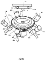
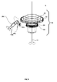
- Figs. 1 show (a) a first embodiment of an optical blood analyte monitor according to the present invention and (b) cooperation between the detector and the filter arrangement of Fig. 1 (a);
- Fig. 2 shows a part sectional view of the tilting filter arrangement of Fig. 1;
- Fig. 3 shows in greater detail the drive arrangement of the tilting filter arrangement of Figs. 1 and Fig. 2;
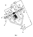
- Fig. 4 shows a second embodiment of an optical blood analyte monitor according to the present invention.
- a non-invasive blood analyte monitor 2 is shown generally to comprise a near infra-red light source having a plurality (here five are shown) of light emitters 4a...e; a complementary detection means 6 and a tilting filter arrangement 8.
- a control unit 10 is provided in the present embodiment for controlling the energisation of each emitter 4a...e and is also operably connected to a computer 12 from which control instructions are sent to the control unit 10 and which is operably connected to receive output, such as indicative of an intensity of light incident at the detection means 6, from the detection means 6.
- the computer 12 in the present embodiment, also serves as a data analyser for the analysis of the output to determine a blood glucose level which may then be conveniently provided as audio/visual information for a user, perhaps being displayed on a dedicated display unit (not shown) of generally known type, preferably integral with the monitor.
- a dedicated display unit (not shown) of generally known type, preferably integral with the monitor.
- the computer 12 is provided access to a chemometric model linking spectral features to blood glucose level. Indeed any analyte of interest having characteristic optical absorptions may be determined by construction of a suitable chemometric model.
- the computer 12 is in the present embodiment configured to hold in memory a calibration model based on one of a number of known regression techniques applied to spectral measurements of a large number of samples in which the blood glucose level (or other analyte of interest) is known and is varied between samples so as to extend across the expected range of blood glucose levels.
- Generally known calibration methods capable of simultaneously using measurements from a very large number of wavelengths may be employed. Such methods typically employ known multivariate mathematical techniques such as partial least squares (PLS) or multiple linear regression (MLR) or principle component analysis (PCA) techniques. These methods, which are capable of analyzing rather complex materials, have a number of inherent advantages (e.g., signal averaging and improved outlier detection) over methods that use relatively few wavelengths. While still allowing for overlapped spectra of various components, the capability of using many wavelengths eliminates the need for wavelength selection and the implicit requirement of knowledge of the spectra of interfering components. The number of potential spectral wavelengths available to use with a full-spectrum method is often very large, perhaps thousands. Thus, with full-spectrum methods, all available wavelengths within some broad range are typically utilized.
- PLS partial least squares
- MLR multiple linear regression
- PCA principle component analysis
- the computer 12 has access to a library of calibration spectra that may be held in a memory associated with the computer 12.
- the computer 12 is configured to select a g roup of calibration spectra which most closely resembles the spectrum to be analysed and to generate, from those selected calibration spectra, a calibration model which is then applied in the computer 12 to determine the glucose level from the spectrum to be analysed.
- each emitter 4a...e consists of a light emitting diode (LED) having a narrow (for example, of the order of 100nm) wavelength band emission profile that together cover desired portions of the near infra-red wavelength region between 780 nm to 2500nm.
- LED light emitting diode
- This, for blood glucose monitors preferably includes wavelength bands extending over some or all of the wavelength region between 1000nm and 2000nm.
- one or more LEDs may be selected having near infra-red emissions in regions not well absorbed by the blood glucose, or any material making up the tissue sample being illuminated. Light which is detected after interaction with the tissue sample may then be used as a reference, employed in the optical calibration of the monitor according to the present invention.
- the detection means 6 may include a known InGaAs solid state detector.
- emitters 4a...e are arranged angularly spaced apart around a central axis 14 and each is orientated to provide a different associated light path (represented generally by dashed lines 16a,b,c and e) all of which intersect, here approximately at the central axis 14 in what in the present embodiment is an analysing region 18.
- the appropriate body part is located analysing region 18 so as to be capable of being illuminated with light from any emitter 4a...e.
- Fig. 1 (a) it will be appreciated that the ear lobe or other site offering convenient access may be substituted.
- the tilting filter arrangement 8 comprises a plurality of interference filters 20 a...e, each one selected to have a different narrow band pass (in the present example employing the LED's described above, of the order of 10nm) adapted for its associated emitter 4a...e.
- Each filter (20c, for example) is located in a light path (16c,for example) of the associated emitter (4c, for example) and is tiltable to vary an angle of incidence ? of light from the associated emitter 4c on a face (22c, for example) of the filter 20c .
- the wavelength of the incident light that is transmitted by the filter 20c may be varied as the angle of incidence ? is varied.
- the same will of course be true for all filters 20a..e and associated emitter 4a..e combinations.
- the detection means 6 is here illustrated as comprising a single sensor that in use is positioned (shown by the arrow in Fig. 1 (b)) to monitor light from the LEDs after it is reflected from a body portion (not shown) which is here to be located in the analysing region 18. It will be appreciated that the detection means 6 may be configured to additionally or alternatively monitor light from the LEDs after it is transmitted through the sample, without departing from the invention as claimed.
- the detector means 6 is intended to be positioned in an opening 24 of a through bore 26 that extends axially along a body portion 28 of the tilting filter arrangement 8.
- the through bore 26 is optionally provided with a light reflecting internal surface 30 and forms a light pipe for the channelling of light to the detection means 6 after its interaction with the body part in the analysing region 18.
- the body portion 28 further comprises a section 28a formed of material which is transparent to the radiation emitted from the emitters 4a..e and which terminates at the analysing region 18. In this way the positioning of the body part in the analysing region 18 is facilitated as it simply may be pressed against the end of the transparent section 28a.
- the body portion 28 is here provided with a lip 32 which is intended to form a part of a light tight housing for the detection means 6.
- a complementary lid 34 is also provided to complete the light tight housing and is here includes bearings, such as a wheel race 36 that engages with an internal surface 38 of the lip 32 so that the lid 34 will remain stationary as the body portion 28 rotates about the axis 14.
- the lid 34 also acts as a support for the detector means 6 and may be formed of a printed circuit board holding other electronic components of the analyser 2.
- a toothed drive wheel 40 intended for engagement with a complementary toothed wheel of a drive system, such as a stepper motor based system (not shown), which in operation is intended to cause the body portion 28 to rotate, preferably describing an oscillatory motion, about the central axis 14, as illustrated by the double headed arrow in Fig 2.
- FIG.3 the tilting filter arrangement 8 of Figs. 1 and Fig. 2 is shown in greater detail and for ease of understanding it is illustrated as having only one filter 20c.
- the filter arrangement comprises an axle 42 having the cylindrical body portion 28 extending along the rotational axis 14. At one end of the body portion 28, distal the analysing region (not shown), there is provided the lip 32 and the toothed drive wheel 40.
- a carrier here in the form of a toothed gear wheel 44 is located about the periphery of the body portion 28 and is presently also included as an integral part of the axle 42.
- the axle 42 may be manufactured as a single item, typically using conventional moulding techniques, such as injection moulding. This facilitates the low cost volume production of the filter arrangement 8 employing a minimum of separate parts.
- Each filter 20c is provided in mechanical connection with an associated follower, here in the form of a toothed gear wheel 46c, which engages with and is moved, here rotated, by the carrier gear wheel 44 as the axle 42 rotates.
- each filter 20c is mounted on a shaft 48c of the associated gear wheel 46c to tilt as the gear wheel 46c (and hence the shaft 48c) rotates and thereby vary the angle of incidence, ?, of light at the filter 20c whilst always remaining in the light path (16c say of Figs. 1 and Fig. 2)as the axle 42 rotates.
- axle 42 and thus the gear wheel 46c is oscillated through only an arc of a circle sufficient to achieve a desired reciprocative tilting movement of the associated filter 20c, preferably but not essentially, about a position where the light is incident substantially perpendicular to a face (22c in Fig. 1(b) of the filter 20c.
- the wavelength of light from an associated emitter that will be incident at the analysing region may be swept through a desired range first in one wavelength direction and then in the opposite wavelength direction.
- the follower gear wheel 46c need only comprise a restricted segment 50c of a circle (broken line construction). It will be appreciated that the same is also true for the carrier gear wheel 44. However it is convenient to provide the carrier gear wheel 44 as a continuous gear wheel since it is to engage each of the plurality of follower gear wheels at different locations about the circumference of the body 28.
- a detection means 6 should be selected having wavelength response characteristics matching those emission wavelength characteristics of the emitters used and it is envisaged that multiple sensors may be used, particularly in circumstances where there is a large variation in the emission spectral regions of the emitters 4a..e that constitute the light source of the optical analyser 2.
- the detection means 6 may also be arranged to detect light after its transmission through the sample.
- the detection means 6 may be located to along the axis 14 beyond the body portion 28 such that the analysis region 18 is situated between the body portion 28 and the detection means 6. In this configuration the body portion 28 need not be hollow and will form a solid rotatable axle supporting the carrier 44 and the drive wheel 40.
- the emission wavelength band of each emitter is different and that the wavelength bands together cover portions of the visible and infra-red wavelength regions and are selectably, typically sequentially, energisable dependent on the sample being analysed.
- a general purpose analyser may be provided that can analyse a wide variety of samples.
- this first embodiment of the present invention may be provided having two or more emitters of the plurality 4a..e that have substantially the same emission wavelength band and which are energised to simultaneously illuminate a sample. In this manner an 'average' illumination of the sample is provided which is relatively insensitive to changes of individual emitters.
- an optical analyser configured in this manner need not be re-calibrated each time an emitter is replaced.
- FIG. 4 a second embodiment of a tilting filter arrangement 52 is illustrated together with relevant components of a second optical analyser 54.
- Each of a plurality of interference filters 56a..d of the tilting filter arrangement 52 is ganged on a shaft 58 for simultaneous tilting movement as the shaft 58 rotates.
- the shaft 58 is journalled in bearings 60 for rotation about an axis 62.
- a toothed follower 64 is formed about at least a portion of the circumference of the shaft 58 and is adapted for engagement with a complementary carrier portion 66 provided on an underside of a drive-plate 68.
- the drive-plate 68 is reciprocatively translated (illustrated by the heavier double-headed arrow)to effect a corresponding reciprocal rotation of the shaft 68 (illustrated by the lighter double-headed arrow).
- all filters 56a..d are simultaneously caused to execute a reciprocative tilting motion.
- This tilting motion serves to vary an angle of incidence of light at a surface of an associated filter of the plurality of filters 56a..d whilst each filter 56a..d remains in the light path of the associated emitter 70a..d at all times.
- the plurality of light emitters 70a..d constitute a light source of the optical analyser 54.
- each light emitter 70a..d is optically coupled with a different one of the plurality of interference filters 56a..d. It is also envisaged that light emitters having substantially the same emission wavelength band profile may be all coupled to a same filter.
- the filters 56a..d are tilted the wavelength of light emitted from an associated emitter of a plurality of emitters 70a..d and passed by each filter of the plurality 56a..d for onward transmission to an analysing region 72 may be swept backwards and forwards through a desired range.
- a fibre optic bundle 74 for collecting light passed by the filters 56a..d.
- the bundle 74 is configured with a plurality of branches 74a..d, each for collecting light passed by a different one of the filters 56a..d.
- an optical coupling means here illustrated as individual lenses 76a..d, may be provided to couple the light passed by each filter 56a..d into the fibre optic bundle 74.
- the analysis region 72 which here is located between the end 78 and detection means 80 and in which a body part, such as a finger or an ear lobe (not shown), may be introduced.
- the analysis region 72 may be configured to receive a blood sample confined in a cuvette, or other suitable holder or on a carrier such as a test strip transparent slide or other support surface.
- a signal representative of the intensity of the so detected light is to be passed to a data processor within a computing element 82.
- the data processor is configured to manipulate the signal in a known manner using an appropriate chemometric model to provide analysis results for a user as discussed above with reference to the computer 12 of Fig 1.
- control unit 84 for the light source 70a..d and is configured to energise the emitters 70a..d in manner, such as sequentially, group-wise or individually in a non-sequential manner, dependent on control signals output from the computing element 82 and the type of analysis to be made.
- the angular position of the shaft 58 may be monitored using elements well known in the art and provided to the computing element 82.
- Such elements may be, for example and without limitation, a shaft encoder associated with the shaft 58 or a position sensor associated with the drive plate 68 or a pulse counter associated with a stepper motor drive element (if employed) to count drive pulses sent to the motor. From this a determination of angle of tilt of the plurality of filters 56a..d may be made and hence the wavelength being passed by each illuminated filter 56a..d can be readily calculated in the computing element 82.
- the intensity of transmitted light detected by the detection means 80 can be then easily indexed with the incident wavelength and a transmission spectrum can be constructed.
Landscapes
- Health & Medical Sciences (AREA)
- Physics & Mathematics (AREA)
- Life Sciences & Earth Sciences (AREA)
- Pathology (AREA)
- Spectroscopy & Molecular Physics (AREA)
- General Health & Medical Sciences (AREA)
- Surgery (AREA)
- Public Health (AREA)
- Biomedical Technology (AREA)
- Heart & Thoracic Surgery (AREA)
- Medical Informatics (AREA)
- Molecular Biology (AREA)
- Biophysics (AREA)
- Animal Behavior & Ethology (AREA)
- Optics & Photonics (AREA)
- Engineering & Computer Science (AREA)
- Veterinary Medicine (AREA)
- Chemical & Material Sciences (AREA)
- Analytical Chemistry (AREA)
- Biochemistry (AREA)
- General Physics & Mathematics (AREA)
- Immunology (AREA)
- Emergency Medicine (AREA)
- Measurement Of The Respiration, Hearing Ability, Form, And Blood Characteristics Of Living Organisms (AREA)
- Investigating Or Analysing Materials By Optical Means (AREA)
Priority Applications (3)
| Application Number | Priority Date | Filing Date | Title |
|---|---|---|---|
| EP06120413A EP1897486A1 (fr) | 2006-09-11 | 2006-09-11 | Dispositif de surveillance optique de substances sanguines à analyser |
| US11/543,841 US20070027374A1 (en) | 2005-05-19 | 2006-10-06 | Optical blood analyte monitor |
| PCT/EP2007/059341 WO2008031756A1 (fr) | 2006-09-11 | 2007-09-06 | Dispositif de surveillance d'analyte sanguin optique |
Applications Claiming Priority (1)
| Application Number | Priority Date | Filing Date | Title |
|---|---|---|---|
| EP06120413A EP1897486A1 (fr) | 2006-09-11 | 2006-09-11 | Dispositif de surveillance optique de substances sanguines à analyser |
Publications (1)
| Publication Number | Publication Date |
|---|---|
| EP1897486A1 true EP1897486A1 (fr) | 2008-03-12 |
Family
ID=37763769
Family Applications (1)
| Application Number | Title | Priority Date | Filing Date |
|---|---|---|---|
| EP06120413A Withdrawn EP1897486A1 (fr) | 2005-05-19 | 2006-09-11 | Dispositif de surveillance optique de substances sanguines à analyser |
Country Status (2)
| Country | Link |
|---|---|
| EP (1) | EP1897486A1 (fr) |
| WO (1) | WO2008031756A1 (fr) |
Citations (7)
| Publication number | Priority date | Publication date | Assignee | Title |
|---|---|---|---|---|
| US4037970A (en) | 1972-08-24 | 1977-07-26 | Neotec Corporation | Optical analyzer for agricultural products |
| US4082464A (en) | 1976-10-07 | 1978-04-04 | Neotec Corporation | Optical analysis system having rotating filters |
| US5529755A (en) | 1994-02-22 | 1996-06-25 | Minolta Co., Ltd. | Apparatus for measuring a glucose concentration |
| US5774213A (en) * | 1995-04-21 | 1998-06-30 | Trebino; Rick P. | Techniques for measuring difference of an optical property at two wavelengths by modulating two sources to have opposite-phase components at a common frequency |
| US5830132A (en) * | 1993-08-24 | 1998-11-03 | Robinson; Mark R. | Robust accurate non-invasive analyte monitor |
| US6124134A (en) | 1993-06-25 | 2000-09-26 | Stark; Edward W. | Glucose related measurement method and apparatus |
| WO2001016577A1 (fr) * | 1999-08-31 | 2001-03-08 | Cme Telemetrix Inc. | Procede de determination d'analytes au moyen d'un spectre en proche infrarouge, d'un spectre visible adjacent et de longueurs d'ondes distinctes de spectre en proche infrarouge |
Family Cites Families (5)
| Publication number | Priority date | Publication date | Assignee | Title |
|---|---|---|---|---|
| US4738535A (en) * | 1986-07-22 | 1988-04-19 | Pacific Scientific Company | Optical instrument employing fiber optics to direct light through tilting filter wheel |
| US5028787A (en) * | 1989-01-19 | 1991-07-02 | Futrex, Inc. | Non-invasive measurement of blood glucose |
| US5747806A (en) * | 1996-02-02 | 1998-05-05 | Instrumentation Metrics, Inc | Method and apparatus for multi-spectral analysis in noninvasive nir spectroscopy |
| US7271912B2 (en) * | 2003-04-15 | 2007-09-18 | Optiscan Biomedical Corporation | Method of determining analyte concentration in a sample using infrared transmission data |
| EP1882166A1 (fr) * | 2005-05-19 | 2008-01-30 | FOSS Analytical AB | Analyseur optique |
-
2006
- 2006-09-11 EP EP06120413A patent/EP1897486A1/fr not_active Withdrawn
-
2007
- 2007-09-06 WO PCT/EP2007/059341 patent/WO2008031756A1/fr not_active Ceased
Patent Citations (7)
| Publication number | Priority date | Publication date | Assignee | Title |
|---|---|---|---|---|
| US4037970A (en) | 1972-08-24 | 1977-07-26 | Neotec Corporation | Optical analyzer for agricultural products |
| US4082464A (en) | 1976-10-07 | 1978-04-04 | Neotec Corporation | Optical analysis system having rotating filters |
| US6124134A (en) | 1993-06-25 | 2000-09-26 | Stark; Edward W. | Glucose related measurement method and apparatus |
| US5830132A (en) * | 1993-08-24 | 1998-11-03 | Robinson; Mark R. | Robust accurate non-invasive analyte monitor |
| US5529755A (en) | 1994-02-22 | 1996-06-25 | Minolta Co., Ltd. | Apparatus for measuring a glucose concentration |
| US5774213A (en) * | 1995-04-21 | 1998-06-30 | Trebino; Rick P. | Techniques for measuring difference of an optical property at two wavelengths by modulating two sources to have opposite-phase components at a common frequency |
| WO2001016577A1 (fr) * | 1999-08-31 | 2001-03-08 | Cme Telemetrix Inc. | Procede de determination d'analytes au moyen d'un spectre en proche infrarouge, d'un spectre visible adjacent et de longueurs d'ondes distinctes de spectre en proche infrarouge |
Also Published As
| Publication number | Publication date |
|---|---|
| WO2008031756A1 (fr) | 2008-03-20 |
Similar Documents
| Publication | Publication Date | Title |
|---|---|---|
| EP3326521B1 (fr) | Système compact de spectrométrie pour mesure non invasive de spectres de transmission et d'absorption dans des échantillons de tissus biologiques | |
| CN1185478C (zh) | 无损伤性红外分光术中多光谱分析用的方法和装置 | |
| US6741875B1 (en) | Method for determination of analytes using near infrared, adjacent visible spectrum and an array of longer near infrared wavelengths | |
| US20070027374A1 (en) | Optical blood analyte monitor | |
| US5054487A (en) | Laser systems for material analysis based on reflectance ratio detection | |
| US5360004A (en) | Non-invasive determination of analyte concentration using non-continuous radiation | |
| US6064897A (en) | Sensor utilizing Raman spectroscopy for non-invasive monitoring of analytes in biological fluid and method of use | |
| US6124134A (en) | Glucose related measurement method and apparatus | |
| EP0877926B1 (fr) | Appareil d'analyse multispectrale en spectroscopie non invasive pratiquee dans le proche infrarouge | |
| JP2003508745A (ja) | 近赤外、隣接可視スペクトルおよびより長い近赤外波長のアレイを使用する被分析対象の判定方法 | |
| US5703364A (en) | Method and apparatus for near-infrared quantitative analysis | |
| US20220031201A1 (en) | Method and system for non-invasive blood glucose measurement using signal change of the non-glucose components induced by the presence of glucose | |
| WO2001016577A1 (fr) | Procede de determination d'analytes au moyen d'un spectre en proche infrarouge, d'un spectre visible adjacent et de longueurs d'ondes distinctes de spectre en proche infrarouge | |
| US7576855B2 (en) | Spectrophotometric method and apparatus | |
| JPH11183377A (ja) | 光学式成分計 | |
| EP0623307A1 (fr) | Détermination non-invasive de la concentration de constituants par radiation non-continue | |
| WO2008031756A1 (fr) | Dispositif de surveillance d'analyte sanguin optique | |
| US20090290159A1 (en) | Optical Analyser | |
| JPH07136151A (ja) | 血液成分の濃度を検出する方法及び装置並びにこの装置を較正するための装置 | |
| JP2002065645A (ja) | 非侵襲血糖計 | |
| US8523785B2 (en) | Method and apparatus for measuring analytes | |
| US5981951A (en) | Method and a system for determination of components of a substance | |
| Oh et al. | The high-quality spectral fingerprint of glucose captured by Raman spectroscopy in non-invasive glucose measurement | |
| AU713502C (en) | Method and apparatus for multi-spectral analysis in noninvasive NIR spectroscopy | |
| HK1019635B (en) | Method and apparatus for multi-spectral analysis in noninvasive nir spectroscopy |
Legal Events
| Date | Code | Title | Description |
|---|---|---|---|
| PUAI | Public reference made under article 153(3) epc to a published international application that has entered the european phase |
Free format text: ORIGINAL CODE: 0009012 |
|
| AK | Designated contracting states |
Kind code of ref document: A1 Designated state(s): AT BE BG CH CY CZ DE DK EE ES FI FR GB GR HU IE IS IT LI LT LU LV MC NL PL PT RO SE SI SK TR |
|
| AX | Request for extension of the european patent |
Extension state: AL BA HR MK YU |
|
| STAA | Information on the status of an ep patent application or granted ep patent |
Free format text: STATUS: THE APPLICATION HAS BEEN WITHDRAWN |
|
| 18W | Application withdrawn |
Effective date: 20080328 |