EP1897520A1 - Opthalmologische Vorrichtung für die refraktive Korrektur eines Auges. - Google Patents
Opthalmologische Vorrichtung für die refraktive Korrektur eines Auges. Download PDFInfo
- Publication number
- EP1897520A1 EP1897520A1 EP06405385A EP06405385A EP1897520A1 EP 1897520 A1 EP1897520 A1 EP 1897520A1 EP 06405385 A EP06405385 A EP 06405385A EP 06405385 A EP06405385 A EP 06405385A EP 1897520 A1 EP1897520 A1 EP 1897520A1
- Authority
- EP
- European Patent Office
- Prior art keywords
- eye
- focal point
- processing
- starting points
- module
- Prior art date
- Legal status (The legal status is an assumption and is not a legal conclusion. Google has not performed a legal analysis and makes no representation as to the accuracy of the status listed.)
- Granted
Links
Images

Classifications
-
- A—HUMAN NECESSITIES
- A61—MEDICAL OR VETERINARY SCIENCE; HYGIENE
- A61F—FILTERS IMPLANTABLE INTO BLOOD VESSELS; PROSTHESES; DEVICES PROVIDING PATENCY TO, OR PREVENTING COLLAPSING OF, TUBULAR STRUCTURES OF THE BODY, e.g. STENTS; ORTHOPAEDIC, NURSING OR CONTRACEPTIVE DEVICES; FOMENTATION; TREATMENT OR PROTECTION OF EYES OR EARS; BANDAGES, DRESSINGS OR ABSORBENT PADS; FIRST-AID KITS
- A61F9/00—Methods or devices for treatment of the eyes; Devices for putting in contact-lenses; Devices to correct squinting; Apparatus to guide the blind; Protective devices for the eyes, carried on the body or in the hand
- A61F9/007—Methods or devices for eye surgery
- A61F9/008—Methods or devices for eye surgery using laser
- A61F9/00825—Methods or devices for eye surgery using laser for photodisruption
- A61F9/00827—Refractive correction, e.g. lenticle
-
- A—HUMAN NECESSITIES
- A61—MEDICAL OR VETERINARY SCIENCE; HYGIENE
- A61F—FILTERS IMPLANTABLE INTO BLOOD VESSELS; PROSTHESES; DEVICES PROVIDING PATENCY TO, OR PREVENTING COLLAPSING OF, TUBULAR STRUCTURES OF THE BODY, e.g. STENTS; ORTHOPAEDIC, NURSING OR CONTRACEPTIVE DEVICES; FOMENTATION; TREATMENT OR PROTECTION OF EYES OR EARS; BANDAGES, DRESSINGS OR ABSORBENT PADS; FIRST-AID KITS
- A61F9/00—Methods or devices for treatment of the eyes; Devices for putting in contact-lenses; Devices to correct squinting; Apparatus to guide the blind; Protective devices for the eyes, carried on the body or in the hand
- A61F9/007—Methods or devices for eye surgery
- A61F9/008—Methods or devices for eye surgery using laser
- A61F9/00825—Methods or devices for eye surgery using laser for photodisruption
- A61F9/00838—Correction of presbyopia
-
- A—HUMAN NECESSITIES
- A61—MEDICAL OR VETERINARY SCIENCE; HYGIENE
- A61F—FILTERS IMPLANTABLE INTO BLOOD VESSELS; PROSTHESES; DEVICES PROVIDING PATENCY TO, OR PREVENTING COLLAPSING OF, TUBULAR STRUCTURES OF THE BODY, e.g. STENTS; ORTHOPAEDIC, NURSING OR CONTRACEPTIVE DEVICES; FOMENTATION; TREATMENT OR PROTECTION OF EYES OR EARS; BANDAGES, DRESSINGS OR ABSORBENT PADS; FIRST-AID KITS
- A61F9/00—Methods or devices for treatment of the eyes; Devices for putting in contact-lenses; Devices to correct squinting; Apparatus to guide the blind; Protective devices for the eyes, carried on the body or in the hand
- A61F9/007—Methods or devices for eye surgery
- A61F9/008—Methods or devices for eye surgery using laser
- A61F2009/00844—Feedback systems
- A61F2009/00846—Eyetracking
-
- A—HUMAN NECESSITIES
- A61—MEDICAL OR VETERINARY SCIENCE; HYGIENE
- A61F—FILTERS IMPLANTABLE INTO BLOOD VESSELS; PROSTHESES; DEVICES PROVIDING PATENCY TO, OR PREVENTING COLLAPSING OF, TUBULAR STRUCTURES OF THE BODY, e.g. STENTS; ORTHOPAEDIC, NURSING OR CONTRACEPTIVE DEVICES; FOMENTATION; TREATMENT OR PROTECTION OF EYES OR EARS; BANDAGES, DRESSINGS OR ABSORBENT PADS; FIRST-AID KITS
- A61F9/00—Methods or devices for treatment of the eyes; Devices for putting in contact-lenses; Devices to correct squinting; Apparatus to guide the blind; Protective devices for the eyes, carried on the body or in the hand
- A61F9/007—Methods or devices for eye surgery
- A61F9/008—Methods or devices for eye surgery using laser
- A61F2009/00844—Feedback systems
- A61F2009/00848—Feedback systems based on wavefront
-
- A—HUMAN NECESSITIES
- A61—MEDICAL OR VETERINARY SCIENCE; HYGIENE
- A61F—FILTERS IMPLANTABLE INTO BLOOD VESSELS; PROSTHESES; DEVICES PROVIDING PATENCY TO, OR PREVENTING COLLAPSING OF, TUBULAR STRUCTURES OF THE BODY, e.g. STENTS; ORTHOPAEDIC, NURSING OR CONTRACEPTIVE DEVICES; FOMENTATION; TREATMENT OR PROTECTION OF EYES OR EARS; BANDAGES, DRESSINGS OR ABSORBENT PADS; FIRST-AID KITS
- A61F9/00—Methods or devices for treatment of the eyes; Devices for putting in contact-lenses; Devices to correct squinting; Apparatus to guide the blind; Protective devices for the eyes, carried on the body or in the hand
- A61F9/007—Methods or devices for eye surgery
- A61F9/008—Methods or devices for eye surgery using laser
- A61F2009/00861—Methods or devices for eye surgery using laser adapted for treatment at a particular location
- A61F2009/0087—Lens
-
- A—HUMAN NECESSITIES
- A61—MEDICAL OR VETERINARY SCIENCE; HYGIENE
- A61F—FILTERS IMPLANTABLE INTO BLOOD VESSELS; PROSTHESES; DEVICES PROVIDING PATENCY TO, OR PREVENTING COLLAPSING OF, TUBULAR STRUCTURES OF THE BODY, e.g. STENTS; ORTHOPAEDIC, NURSING OR CONTRACEPTIVE DEVICES; FOMENTATION; TREATMENT OR PROTECTION OF EYES OR EARS; BANDAGES, DRESSINGS OR ABSORBENT PADS; FIRST-AID KITS
- A61F9/00—Methods or devices for treatment of the eyes; Devices for putting in contact-lenses; Devices to correct squinting; Apparatus to guide the blind; Protective devices for the eyes, carried on the body or in the hand
- A61F9/007—Methods or devices for eye surgery
- A61F9/008—Methods or devices for eye surgery using laser
- A61F2009/00861—Methods or devices for eye surgery using laser adapted for treatment at a particular location
- A61F2009/00872—Cornea
-
- A—HUMAN NECESSITIES
- A61—MEDICAL OR VETERINARY SCIENCE; HYGIENE
- A61F—FILTERS IMPLANTABLE INTO BLOOD VESSELS; PROSTHESES; DEVICES PROVIDING PATENCY TO, OR PREVENTING COLLAPSING OF, TUBULAR STRUCTURES OF THE BODY, e.g. STENTS; ORTHOPAEDIC, NURSING OR CONTRACEPTIVE DEVICES; FOMENTATION; TREATMENT OR PROTECTION OF EYES OR EARS; BANDAGES, DRESSINGS OR ABSORBENT PADS; FIRST-AID KITS
- A61F9/00—Methods or devices for treatment of the eyes; Devices for putting in contact-lenses; Devices to correct squinting; Apparatus to guide the blind; Protective devices for the eyes, carried on the body or in the hand
- A61F9/007—Methods or devices for eye surgery
- A61F9/008—Methods or devices for eye surgery using laser
- A61F2009/00878—Planning
- A61F2009/0088—Planning based on wavefront
-
- A—HUMAN NECESSITIES
- A61—MEDICAL OR VETERINARY SCIENCE; HYGIENE
- A61F—FILTERS IMPLANTABLE INTO BLOOD VESSELS; PROSTHESES; DEVICES PROVIDING PATENCY TO, OR PREVENTING COLLAPSING OF, TUBULAR STRUCTURES OF THE BODY, e.g. STENTS; ORTHOPAEDIC, NURSING OR CONTRACEPTIVE DEVICES; FOMENTATION; TREATMENT OR PROTECTION OF EYES OR EARS; BANDAGES, DRESSINGS OR ABSORBENT PADS; FIRST-AID KITS
- A61F9/00—Methods or devices for treatment of the eyes; Devices for putting in contact-lenses; Devices to correct squinting; Apparatus to guide the blind; Protective devices for the eyes, carried on the body or in the hand
- A61F9/007—Methods or devices for eye surgery
- A61F9/008—Methods or devices for eye surgery using laser
- A61F2009/00897—Scanning mechanisms or algorithms
Definitions
- the present invention relates to an ophthalmic device and an ophthalmological method for the refractive correction of an eye. More particularly, the invention relates to an ophthalmologic apparatus and method for refractive correction of an eye by projection of laser pulses to a focal point in the eye for resolution of ocular tissue.
- Apertures such as myopia (myopia), hyperopia (farsightedness or clarity) or astigmatism (astigmatism) can be permanently corrected by refractive surgical treatment.
- Refractive surgical treatments are surgical procedures on the eye, which change the optical power of the eye with the aim of approximating it to a desired value as well as possible.
- transparent materials in the focus can be processed by non-linear absorption and subsequent interaction (eg photodisruption).
- surgical incisions are made in the cornea (cornea) by tissue resolution by means of remote tolaser pulses.
- the distance between the focus diameters of successive laser pulses is after US 5,993,438 preferably one to two times the radius of a bubble generated by one of the laser pulses in the focal point.
- an ablation layer the ocular tissue is dissolved in each case over a thickness of approximately 10 .mu.m.
- the overlying ablation layers are each created directly adjacent to each other, so that the dome-shaped cavity is formed contiguous, without remaining tissue bridges.
- the ophthalmological device which comprises a light projector for projecting laser pulses onto a focal point inside the eye for dissolving eye tissue, additionally comprises a positioning module and a scanning module.
- the positioning module is set up to position the focal point at different starting points.
- the scanning module is arranged to move the focal point from each one of the starting points according to a scanning pattern for a machining sub-area, wherein the scanning pattern and the starting points are defined so that the eye tissue is dissolved in a plurality of processing sections separated by tissue bridges.
- the scanning pattern defines, for example, a machining subregion having a rectangular, round, elliptical, star-shaped or spiral shape or in a shape similar to a Lissajou figure.
- the scanning module comprises, for example, a galvanoscanner, a resonant mirror scanner, an acoustic optical modulator, a polygon scanner and / or a microelectromechanical scanner.
- the positioning module includes motion drivers for mechanically displacing at least portions of the light projector and / or a galvano scanner for deflecting the laser pulses.
- the light projector preferably has a numerical aperture of more than 0.3.
- the ophthalmic device includes, for example, a control module configured to control the positioning module and the scanning module such that the positioning module positions the focal point at different starting points and that the scanning module moves the focal point from one of the starting points according to the scanning pattern the ocular tissue is dissolved in a plurality of processing sections separated by tissue bridges.
- a control module configured to control the positioning module and the scanning module such that the positioning module positions the focal point at different starting points and that the scanning module moves the focal point from one of the starting points according to the scanning pattern the ocular tissue is dissolved in a plurality of processing sections separated by tissue bridges.
- the processing subregions may be arranged in an annular cluster in the (intrastromal) corneal tissue so that hyperopia can be corrected.
- the corneal curvature can be suitably changed to correct astigmatism and higher order aberrations.
- the positioning module is set up to position the focal point in each case at starting points on a first processing surface
- the scanning module is set up to move the focal point in this first processing surface.
- the ophthalmological apparatus further comprises a depth positioning module for shifting the focal point along a projection axis of the light projector into a second, eg parallel, second processing surface equidistant from the first processing surface, so that the focal point in the second processing surface can be positioned at different starting points and from each one of the starting points according to FIG Scanning pattern is movable.
- a plurality of focal surfaces eg focal planes
- the depth positioning of the Focal point thus allows a multi-layer processing of the eye tissue, each with a plurality of separate, non-contiguous processing subdomains in which the eye tissue is dissolved.
- the distance between individual focal surfaces or processing surfaces is preferably determined such that in the case of superimposed processing subregions of adjacent processing surfaces, in each case one tissue bridge remains.
- control module is also preferably arranged to control the depth positioning module so that when moving the focal point a minimum distance between the processing surfaces is maintained, the minimum distance is defined so that in equidistant (parallel) processing surfaces overlying processing subregions by fabric bridges from each other are separated.
- the purpose and advantage of the fabric bridges is that defined Abtrag Mrsdicken can be generated. It has been found that internal gas pressures generated during laser processing produce a deformation of the tissue which severely impairs the precision in the stratified removal of large contiguous layers, as described in the prior art.
- control module is set up in accordance with a desired refractive correction of the eye to determine the number of processing subregions and the starting points for the local distribution of the processing subregions in a plurality of processing surfaces in the interior of the eye.
- the control module determines the local distribution of the processing subregions, for example based on a model of the eye tissue to be treated, eg a cornea model, given size and shape of the processing subdomains and given vertical and horizontal minimum distances of individual processing subdomains.
- control module is also set up to select different scanning patterns for processing areas of different sizes.
- the device comprises a wavefront detector for determining a wavefront profile of a light beam reflected by the eye.
- the control module is further configured to set the starting points based on the particular wavefront history. That is, the control module is configured to determine the local distribution of the processing subregions based on the determined wavefront history.
- the scanning module is preferably set up to successively position the following laser pulses such that their focal diameters partially overlap.
- their focus diameter overlap at least to half their diameter.
- laser pulses can be used with less pulse energy for tissue resolution, whereby only small mechanical stresses induced by gas and cavitation bubbles in the residual tissue, which helps in the formation of uniformly thin Abtrags Kunststoffe and a defined collapse of the processing subregions is conducive.
- very regular Abtragsvolumina can generate low height and low aspect ratio (approach to sphere). It is even possible with high numerical aperture and pulses of very short duration and low energy to produce gas-poor or even gas-free cuts. Overheating, as mentioned in the prior art, does not occur even with large overlaps of individual laser pulses.
- the scanning module is arranged to move the focal point much faster than the speed of movement of a human eye in a viewing direction change. While the eye does not mechanically fix and move during the treatment, while the size of the machining sub-area defined by the scanning pattern can be easily changed by eye movement, the scanning module moves the focus fast enough to prevent the machining sub-area from being affected the eye movements remain tissue bridges.
- the device comprises an eye monitoring module for determining eye movements, and is set up to control the positioning module based on the determined eye movements for a corresponding positioning compensation. Since the positioning module positions the focal point at a much lower frequency than the scanning module, eye movements also have a correspondingly greater effect on the positioning of the focal point at the starting points.
- the influence of eye movement can be compensated for each time the focus is positioned at a new starting point.
- the high deflection speed of the scanning module for the generation of cavities according to the scanning pattern and the compensation of eye movements in the positioning of the starting points allow the refractive correction of the eye, without having to fix the eye on the light projector. Due to the high number of processing subareas, for example one hundred, motion artifacts average out of the result of the removal.
- the generation of the plurality of separate cavities with high deflection speed and the compensation of eye movements in the positioning of the cavities thus allow the refractive correction of the eye by means of laser pulses, without the eye and / or the patient mechanically connected or fixed in any form with the laser system Need to become.
- the scanning pattern defines a processing subregion whose diameter is smaller than the thickness of the cornea. If the dimensions of the processing part area with dissolved ocular tissue are smaller than the thickness of the cornea, then the apparent thickness loss at the corneal surface is smaller than the height of the dissolved ocular tissue, especially if the processing part area with the dissolved ocular tissue is away from the corneal surface is (for example, more than half of a focus diameter). The lateral extent (diameter) and the depth positioning of a machining part area can influence this effect (the limited thickness reduction at the corneal surface). Thus, by processing subregions whose diameter is smaller than the thickness of the cornea, refractive power changes can be achieved that are smaller than the refractive power change corresponding to the dissolved tissue height.
- LASIK Laser In situ Keratomileusis
- a corneal ablation of 12 ⁇ m corresponds to approximately one diopter.
- corrections of the refractive power can be made that are finer than would be possible by an extended tissue resolution of the same height by means of the same laser pulses.
- reference numeral 1 denotes an ophthalmological device, or an ophthalmological device arrangement, with a laser source 17 and an optical Lichiprojection module 11 optically connected to the laser source 17 for generating and focused projection of a pulsed laser beam L 'for punctiform tissue resolution at a focal point F (focus) inside the eye tissue, for example in the Cornea 21 (cornea).
- the laser source 17 is arranged in a separate housing or in a housing common to the light projection module 11.
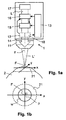
- FIG. 1a shows the ophthalmological device 1 schematically and simplified.
- the optical light projection module 11 has a high numerical aperture of at least 0.3 and preferably more than 0.4, that the ophthalmic device 1 optionally has a suction ring for attachment to the eye 2, or that the ophthalmologic Device 1 optionally a Kantakt Score (eg an applanation) for contact-based deformation (eg for applanation) of the eye 2 in the application of the ophthalmic device 1 comprises.
- Kantakt Score eg an applanation
- contact-based deformation eg for applanation
- the ophthalmic device 1 comprises a positioning module 16 and a scanning module 15, which are arranged in the schematically illustrated beam path L between the laser source 17 and the exit of the light projection module 11.
- the person skilled in the art will understand that the positioning module 16 and the scanning module 15 can also be arranged in the reverse order, as shown in FIG. 1a.
- the positioning module 16 and the scanning module 15 are cascaded scanner modules which position and move the focal point F, respectively.
- the positioning module 16 is a much slower scanner module than the scanning module 15.
- the positioning module 16 is set up to position the focal point F at defined starting points.
- the positioning module 16 includes, for example, movement drivers for mechanical displacement of the Light projector 11 or parts of the light projector 11, for example, motion drivers for the lateral displacement of lenses.
- the motion drivers comprise, for example, a drive element for a feed direction x and a drive element for a scanning direction y perpendicular to the feed direction x (see FIG. 1b), for example piezomotors.
- the positioning module 16 comprises a galvanoscanner for deflecting the laser pulses in the feed direction x and / or in the scanning direction y.
- the coordinates of the starting points are preferably supplied to the positioning module 16 by the control module 13, for example point by point or as a file with (eg a sequence of) a plurality of starting points for storage in the positioning module 16.
- the scanning module 15 is set up to move the focal point F starting from the current starting point according to a defined scanning pattern p (see FIG. 1b).
- the scanning module 15 comprises deflection elements, for example a galvanoscanner, a resonant mirror scanner, an acoustic optical modulator (AOM), a polygon scanner or a microelectromechanical scanner (MEM).
- the scanning module 15 for positioning in a relative to the scanning direction y much slower feed direction x movement driver for moving the light projector 11 or parts of the light projector 11, ie the movement in the slower feed direction x of the sample p, for example, by the positioning module 16 be executed.
- the scanning module 15 is set up either fixed for a specific scanning pattern p or for a plurality of selectable scanning patterns p.
- the scanning pattern p defines, for example, a rectangular, circular, elliptical, star-shaped, spiral or Lissajou figure-shaped machining subarea a, and specifies corresponding deflections of the laser pulses in the advancing direction x and in the scanning direction y.
- the scanning pattern p preferably a processing part a whose diameter is smaller than the thickness of the cornea 21.
- the scanning module 15 preferably comprises the control of the deflection elements for moving the focal point F in accordance with the scanning pattern p, but the person skilled in the art will understand that the control can also be performed by the control module 13.
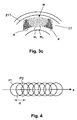
- the scanning module 15 is also configured to deflect the laser pulses so that the focus diameters P1, P2 of successive laser pulses partially overlap. As shown in FIG. 4, the focus diameters P1, P2 of successive laser pulses in the scanning direction s preferably overlap by more than half their diameter, that is, the distance d between the centers of the focus diameters P1, P2 is smaller than the radius of the Focus diameter P1, P2.
- the scanning module 15 is arranged to move the focal point F much faster than the human eye moves in a viewing direction change.
- the scanning module 15 is adapted to deflect the laser pulses so fast that the eye tissue is resolved in a processing area a defined by the scanning pattern without remaining tissue bridges even if the eye 2 moves.
- the entire scanning pattern p for a machining sub-area is traversed by the scanning module 15, for example, in 1 ms (millisecond).
- the scanning module 15 is set up to scan a scan pattern at 20KHz in the feed direction x
- 20 scan lines in the scan direction y may be run in 1 ms, and with a focus diameter in the range 5 ⁇ m to 20 ⁇ m, for example, the eye tissue is reported in a machining subregion a a diameter in the range of about 100 .mu.m to 400 .mu.m resolved (with overlap of the focus diameter P1, P2 in the feed direction x, this value is reduced accordingly).
- a possible eye movement in the x direction will slightly stretch or compress this area, always ensuring a continuous cut.
- An ophthalmic device with a mechanical movement of the light projector and an overlay of an additional fine movement of the focal point F by means of optical microscans is included in the reference by reference EP 1 486 185 described.
- EP 1 486 185 An ophthalmic device with a mechanical movement of the light projector and an overlay of an additional fine movement of the focal point F by means of optical microscans is included in the reference by reference EP 1 486 185 described.
- European Patent Application No. 05 405 376 For example, a scanner module for deflecting the pulsed light beam for the additional fine movement and an optical transmission system for transmitting the deflected femtosecond laser pulses from the scanner module to the light projector 11 and superimposing the deflected femtosecond laser pulses on the movement of the light projector 11 are described.
- the ophthalmic device 1 additionally comprises a depth positioning module 14 for displacing the focal point F along a projection axis z of the light projector 11, for example perpendicular to a working surface spanned by the feed direction x and the scanning direction y, in particular a working plane w.
- the depth positioning module 14 preferably comprises a movable focusing lens and a drive element coupled thereto.
- the light projector 11 is mechanically moved for depth adjustment. As is illustrated in the schematic cross-section of FIG.
- the depth setting of the focal point F defines focal planes or focal surfaces of different depths, which serve as processing planes or processing surfaces w, w 1 , w 2 on which the eye tissue, for example the cornea 21, respectively in FIG a plurality of separate, defined by scanning pattern p processing sub-areas a is resolved.
- the planar processing surfaces w, w 1 , w 2 shown in FIG Machining surfaces w, w 1 , w 2 by appropriately controlled depth adjustment of the focal point F or by use in the light projector 11 of lenses with spherical image fields also curved (concave, convex) are designed, as shown in Figure 3c.
- a cavity arises in each of the processing subregions a, which is separated from the other cavities, both on the same processing surface w, w 1 , w 2, and on adjacent, superimposed processing surfaces w 1 , w 2 , by fabric bridges.
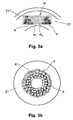
- the processing subareas a are located away from the corneal surface, preferably under the Bowman's membrane 211 of the cornea 21.
- Figure 3b illustrates in plan view an example of a plurality of non-contacting processing subareas a (eg, one hundred or more) arranged in an annular Clusters are arranged side by side and one above the other, to form a plurality of separate, non-contiguous cavities, which collapse and thereby change the corneal curvature suitable for a desired refractive correction of the cornea 21 appropriately.
- a e.g, one hundred or more
- annular Clusters are arranged side by side and one above the other, to form a plurality of separate, non-contiguous cavities, which collapse and thereby change the corneal curvature suitable for a desired refractive correction of the cornea 21 appropriately.
- the ophthalmic device 1 comprises a wavefront detector 18 for determining a wavefront profile of a light beam reflected by the eye 2.
- the reflected light beam is an additional reference light beam which is reflected from the fundus and supplied to the wavefront detector 18 by means of optical elements.
- the wavefront detector is designed, for example, as a Shack-Hartmann sensor, for example after US 2003/0038921 , or as an interferometer, eg as a shearing interferometer. Further possible embodiments of the wavefront detector are shown in FIG Jos. J.
- the control module 13 is set up to determine the currently achieved refractive correction of the cornea 21 based on the determined wavefront profile and, based thereon, to determine the local distribution of further processing subareas a or the starting points for corresponding scanning patterns p in order to achieve the desired refractive correction of the cornea 21 .
- the determination of the wavefront profile and the starting points for further processing subareas a is carried out at different times, for example periodically according to a predetermined time schedule, after the eye tissue has been resolved in all planned processing subareas a on a processing surface w, w 1 , w 2 , after Processing all planned processing subregions a and / or after receiving an input via a user interface instruction signal.
- the ophthalmic device 1 comprises an eye monitoring module 12 (a so-called "eye tracker") for determining eye movements.
- the eye monitoring module 12 comprises, for example, a camera, for example a CCD camera (Charged Coupled Device) and a lighting device (eg LEDs) for detecting a top view of the eye 2, as well as processing means for determining the iris or vein pattern (on the sclera or the retina ) in the field of supervision and to determine eye movements based on relative displacements of the iris or vein pattern.
- the processing means are designed as programmed logic module by means of software and / or hardware and are arranged in a variant in the control module 13.
- Detected eye movements are continuously transmitted by the eye monitoring module 12 to the positioning module 16 or to the control module 13, for example as relative values with respect to a defined reference position of the eye 2 or as viewing direction values of the eye
- the positioning module 16 or the control module 13 is set up to compensate movements of the eye 2 based on the determined eye movements when positioning the focal point F in a starting point.
- the positioning module 16 corrects the coordinates of predetermined starting points based on the detected eye movements or the control module 13 provides the positioning module 16 starting points whose coordinates are adjusted according to the eye movements.
- the control module 13 is preferably implemented as a programmed logic module by means of software and / or hardware.
- the control module 13 is connected to the positioning module 16 and the scanning module 15 for transmitting control signals and / or control data.
- the control module 13 is connected to the wavefront detector 18 and / or the eye monitoring module 12 for receiving feedback or data values via eye movements.
- the control module 13 is arranged in a separate housing or in a housing common with the light projection module 11.
- the control module 13 is set up for a desired refractive correction of the eye 2, in particular the cornea 21, to determine the local distribution of the necessary processing subareas a inside the eye 2, that is, the number of processing subareas a, the respective assigned starting points (in a plurality of processing surfaces) and, in a variant, also the corresponding scanning pattern p or the size, shape and / or orientation of the machining subregions a defined by the scanning pattern p.
- the control module 13 is configured to determine the wavefront profile of a light beam reflected by the eye 2 and thus the current refractive power of the cornea 21 by means of the wavefront detector 18, and based on this, to determine the spatial distribution of the processing subregions a inside the eye 2.
- the control module 13 determines the number and spatial distribution of the processing subareas a, for example based on a table.
- the table assigns to each refractive correction value (and correction type) a number and local distribution of the cropping areas a.
- the control module 13 determines the number and local distribution of the processing subareas a on the basis of a model of the eye tissue to be treated, eg an eye cornea model and information about how the eye 2 images, for a given size and shape of the processing subareas a and at given vertical and horizontal minimum distances of individual processing areas a.
- the information about the number and the local distribution of the processing subareas a can also be transmitted from an external unit to the control module 13.
- the local distribution of the processing subregions a is such that the resulting in the resolution of the eye tissue in the processing subareas a cavities both on the same processing surface w, w 1 , w 2 and in adjacent, superimposed processing surfaces w 1 , w 2 each by fabric bridges are separated from each other.
- the number of processing subareas a can also be determined in a variant from a removal volume that is determined for a specified refractive correction or entered by the user.
- the local arrangement of the processing subareas a is determined by the correction mode, for example, in a myopia, the cornea 21 must be flattened by centralized ablation, whereas in a hyperopia, the curvature of the corneal surface must be made steeper by annular circumferential erosion.
- step S1 the control module 13 determines the desired refractive correction of the eye 2.
- the desired value of the refractive correction is input, for example, via a user interface and detected in the control module 13.
- step S2 the control module 13 determines the local distribution of the processing subareas a to achieve the desired refractive correction.
- control module 13 transmits the starting points for the scanning patterns p of the machining subregions a to the positioning module 16, for example as a sequence of starting points, ordered according to decreasing depth of the machining surface w, w 1 , w 2 .
- identification elements of different sampling patterns p are also assigned to the different starting points.
- control values for different scanning patterns p are also transmitted to the scanning module 15.
- step S4 the treatment of the eye 2 is started by a start signal entered via the user interface.
- step S5 the focal point F is positioned on the lowest-lying working surface w 1 .
- the corresponding control of the depth positioning module 14 is preferably carried out by the control module 13.
- step S6 the positioning module 16 positions the focal point F in the current processing area w, w 1 , w 2 to an unused starting point.
- the positioning takes place according to specification of the starting point by the control module 13 or according to a previously stored in the positioning module 16 sequence of starting points. Positioning also involves constantly monitored eye movements taken into account and compensated either in the control module 13 or in the positioning module 16.
- step S7 the scanning module 15 moves the focal point F in the current processing area w, w 1 , w 2 , starting from the current starting point corresponding to the scanning pattern p associated with the current starting point.
- the sampling pattern p to be used is unchanged, for example, for the entire treatment or is determined by the control module 13 or the positioning module 16, for example when transmitting a synchronization signal, by means of an identification element.
- step S8 the control module 13 checks whether all starting points of the current processing surface w, w 1 , w 2 have already been processed. If starting points to be edited remain, the positioning of the next starting point is performed in step S6. If all assigned starting points have been processed on the current processing surface w, w 1 , w 2 , the control module continues in step S9.
- step S9 the control module 13 checks whether all the processing surfaces w, w 1 , w 2 have already been processed. If machining surfaces w, w 1 , w 2 to be machined remain, focal point F is positioned at step S10 to the next higher, equidistant (eg, parallel) machining surface w, w 2 on which starting points are to be machined, and positioning module 16 moves in step S6 with the positioning of the next starting point. Otherwise, if all the processing surfaces w, w 1 , w 2 have already been processed with starting points to be processed, the control module continues in step S11.
- equidistant eg, parallel
- the wavefront detector 18 determines the wavefront profile of the eye 2 and transmits it to the control module 13 (without steps S11, S12, S13, the method ends in step S14).
- step S12 the control module 13 determines whether the desired refractive correction has been achieved based on the wavefront profile. If the desired correction has been achieved, the control module 13 ends the process in step S14, for example with a success message via the user interface. Otherwise, if the desired refractive correction has not yet been reached, the control module continues in step S13.
- step S13 the control module 13, preferably after confirmation and confirmation via the user interface, determines the local distribution of additional processing subregions a to be processed to achieve the desired refractive correction.
- the processing of the further processing subregions a takes place in step S5, if appropriate after the transmission of the additional starting points to the positioning module 16.
Landscapes
- Health & Medical Sciences (AREA)
- Ophthalmology & Optometry (AREA)
- Heart & Thoracic Surgery (AREA)
- Vascular Medicine (AREA)
- Optics & Photonics (AREA)
- Surgery (AREA)
- Engineering & Computer Science (AREA)
- Biomedical Technology (AREA)
- Physics & Mathematics (AREA)
- Nuclear Medicine, Radiotherapy & Molecular Imaging (AREA)
- Life Sciences & Earth Sciences (AREA)
- Animal Behavior & Ethology (AREA)
- General Health & Medical Sciences (AREA)
- Public Health (AREA)
- Veterinary Medicine (AREA)
- Laser Surgery Devices (AREA)
- Eye Examination Apparatus (AREA)
- Prostheses (AREA)
Abstract
Description
- Die vorliegende Erfindung betrifft eine ophthalmologische Vorrichtung sowie ein ophthalmologisches Verfahren für die refraktive Korrektur eines Auges. Die Erfindung betrifft insbesondere eine ophthalmologische Vorrichtung und ein ophthalmologisches Verfahren für die refraktive Korrektur eines Auges mittels Projektion von Laserpulsen auf einen Brennpunkt im Innem des Auges für eine Auflösung von Augengewebe.
- Fehlsichtigkeiten wie Myopie (Kurzsichtigkeit), Hyperopie (Weitsichtigkeit oder Übersichtigkeit) oder Astigmatismus (Stabsichtigkeit) können heute durch refraktiv-chirurgische Behandlung dauerhaft korrigiert werden. Refraktiv-chirurgische Behandlungen sind chirurgische Eingriffe am Auge, die die optische Brechkraft des Auges ändern mit dem Ziel, diese einem gewünschten Wert möglichst gut anzunähern. Mittels Femtolasersystemen, die Pulsbreiten von typisch 10fs bis 1000fs (1fs=10-15s) aufweisen, können transparente Materialen im Fokus durch nichtlineare Absorption und anschliessende Wechselwirkung (z.B. Photodisruption) bearbeitet werden. Insbesondere werden in der Praxis in der Augenhornhaut (Cornea) durch Gewebeauflösung mittels Ferntolaserpulsen operativ Schnitte erzeugt.
- In der Patentschrift
US 5,993,438 wird ein Verfahren für die refraktive Keratektomie in der Augenhornhaut mittels gepulster Laserstrahlen beschrieben. GemässUS 5,993,438 wird durch Gewebeauflösung im Innern der Augenhornhaut ein domförmiger Hohlraum um die optische Achse erzeugt, welcher beim Kollabieren die Hornhautkrümmung geeignet verändert. Der zusammenhängende Hohlraum wird durch mehrere direkt übereinander liegende Abtragungsschichten gebildet, die zentralsymmetrisch um die optische Achse des Auges angeordnet sind. Jede der Abtragungsschichten wird durch beispielsweise spiralförmig hintereinander gereihte Laserpulse zentralsymmetrisch um die optische Achse herum erzeugt. Mit abnehmender Distanz zu der Hornhautoberfläche weisen die Abtragungsschichten jeweils einen abnehmenden Durchmesser auf. Die Distanz zwischen den Fokusdurchmessem von hintereinander folgenden Laserpulsen beträgt nachUS 5,993,438 vorzugsweise das Ein- bis Zweifache des Radius einer durch einen der Laserpulse im Brennpunkt erzeugten Blase. In einer Abtragungsschicht ist das Augengewebe jeweils über eine Dicke von ungefähr 10µm aufgelöst. Die übereinander liegenden Abtragungsschichten werden jeweils direkt aneinandergrenzend erzeugt, so dass der domförmige Hohlraum zusammenhängend, ohne verbleibende Gewebebrücken gebildet wird. Das Verfahren nachUS 5,993,438 eignet sich zwar für die Behandlung von Myopie, der domförmige Hohlraum ist jedoch nicht für die Korrektur von Hyperopie, Astigmatismus oder Aberrationen (Abbildungsfehler) höherer Ordnung geeignet. - Es ist eine Aufgabe der vorliegenden Erfindung, eine neue ophthalmologische Vorrichtung und ein neues ophthalmologisches Verfahren für die refraktive Korrektur eines Auges mittels Laserpulsen vorzuschlagen, welche insbesondere nicht auf die Korrektur der Kurzsichtigkeit beschränkt sind.
- Gemäss der vorliegenden Erfindung werden diese Ziele insbesondere durch die Elemente der unabhängigen Ansprüche erreicht. Weitere vorteilhafte Ausführungsformen gehen ausserdem aus den abhängigen Ansprüchen und der Beschreibung hervor.
- Die oben genannten Ziele werden durch die vorliegende Erfindung insbesondere dadurch erreicht, dass die ophthalmologische Vorrichtung, welche einen Lichtprojektor umfasst zur Projektion von Laserpulsen auf einen Brennpunkt im Innern des Auges zur Auflösung von Augengewebe, zudem ein Positionierungsmodul und ein Abtastmodul umfasst. Das Positionierungsmodul ist eingerichtet, den Brennpunkt an unterschiedliche Ausgangspunkte zu positionieren. Das Abtastmodul ist eingerichtet, den Brennpunkt ausgehend von jeweils einem der Ausgangspunkte gemäss einem Abtastmuster für ein Bearbeitungsteilgebiet zu bewegen, wobei das Abtastmuster und die Ausgangspunkte so definiert sind, dass das Augengewebe in mehreren durch Gewebebrücken voneinander getrennten Bearbeitungsteilgebieten aufgelöst wird. Das Abtastmuster definiert beispielsweise ein Bearbeitungsteilgebiet mit einer rechteckigen, runden, elliptischen, sternförmigen oder spiralförmigen Form oder in einer Form ähnlich einer Lissajou-Figur. Zum Ablenken der Laserpulse umfasst das Abtastmodul beispielsweise einen Galvanoscanner, einen resonanten Spiegelscanner, einen akustischen optischen Modulator, einen Polygonscanner und/oder einen mikroelektromechanischen Scanner. Das Positionierungsmodul umfasst Bewegungstreiber zum mechanischen Verschieben von mindestens Teilen des Lichtprojektors und/oder einen Galvanoscanner zum Ablenken der Laserpulse. Der Lichtprojektor weist vorzugsweise eine numerische Apertur von über 0.3 auf. Die ophthalmologische Vorrichtung umfasst beispielsweise ein Steuermodul, welches eingerichtet ist, das Positionierungsmodul und das Abtastmodul so zu steuern, dass das Positionierungsmodul den Brennpunkt so an unterschiedliche Ausgangspunkte positioniert und dass das Abtastmodul den Brennpunkt ausgehend von jeweils einem der Ausgangspunkte gemäss dem Abtastmuster so bewegt, dass das Augengewebe in mehreren durch Gewebebrücken voneinander getrennten Bearbeitungsteilgebieten aufgelöst wird. Durch die Bildung einer Vielzahl von getrennten, nicht zusammenhängenden Bearbeitungsteilgebieten mit aufgelöstem Augengewebe ist es möglich die Krümmung der Augenhornhaut nicht bloss wie im Stand der Technik zentralsymmetrisch zur Korrektur einer Myopie abzuflachen, sondern für eine refraktive Korrektur die Krümmung der Augenhornhaut an beinahe beliebigen Stellen und insbesondere auch asymmetrisch zu ändern. Beispielsweise können, durch geeignete Wahl der Ausgangspunkte, mehrere der Bearbeitungsteilgebiete in einem ringförmigen Cluster im (intrastromalen) Homhautgewebe so angeordnet werden, dass eine Hyperopie korrigiert werden kann. Durch unterschiedliche Verteilung der Bearbeitungsteilgebiete in der Hornhaut, sowohl in der Tiefe als auch in der Distanz zur optischen Achse des Auges, und/oder durch mehrschichtige Anordnung der Bearbeitungsteilgebiete im Homhautgewebe kann die Homhautkrümmung zur Korrektur von Astigmatismus und Aberrationen höherer Ordnung geeignet verändert werden. Neben der Behandlung und Korrektur der Augenhornhaut ist es zudem auch möglich, durch die ophthalmologische Vorrichtung auf die gleiche Art das Gewebe der Augenlinse zu behandeln, insbesondere zur Verbesserung der Elastizität der Linse bei Altersweitsichtigkeit.
- In einer bevorzugten Ausführungsvariante ist das Positionierungsmodul eingerichtet, den Brennpunkt jeweils an Ausgangspunkte auf einer ersten Bearbeitungsfläche zu positionieren, und das Abtastmodul ist eingerichtet, den Brennpunkt in dieser ersten Bearbeitungsfläche zu bewegen. Die ophthalmologische Vorrichtung umfasst zudem ein Tiefenpositionierungsmodul zum Verschieben des Brennpunkts entlang einer Projektionsachse des Lichtprojektors in eine zur ersten Bearbeitungsfläche äquidistante, z.B. parallele, zweite Bearbeitungsfläche, so dass der Brennpunkt in der zweiten Bearbeitungsfläche an unterschiedliche Ausgangspunkte positionierbar und ausgehend von jeweils einem der Ausgangspunkte gemäss dem Abtastmuster bewegbar ist. Durch die Tiefenpositionierung des Brennpunkts können mehrere Fokalflächen, z.B. Fokalebenen, eingestellt werden, welche jeweils eine Bearbeitungsfläche, z.B. Bearbeitungsebene, bilden, auf der die Ausgangspunkte jeweils definiert und das Augengewebe in Bearbeitungsteilgebieten aufgelöst wird. Die Tiefenpositionierung des Brennpunkts ermöglicht somit eine mehrschichtige Bearbeitung des Augengewebes mit jeweils einer Vielzahl von getrennten, nicht zusammenhängenden Bearbeitungsteilgebieten, in denen das Augengewebe aufgelöst wird. Vorzugsweise wird dabei die Distanz zwischen einzelnen Fokalflächen respektive Bearbeitungsflächen so bestimmt, dass bei übereinander liegenden Bearbeitungsteilgebieten benachbarter Bearbeitungsflächen, jeweils eine Gewebebrücke bestehen bleibt. Zu diesem Zweck ist das Steuermodul zudem vorzugsweise eingerichtet, das Tiefenpositionierungsmodul so zu steuern, dass beim Verschieben des Brennpunkts eine Mindestdistanz zwischen den Bearbeitungsflächen eingehalten wird, wobei die Mindestdistanz so definiert ist, dass in äquidistanten (parallelen) Bearbeitungsflächen über einander liegende Bearbeitungsteilgebiete durch Gewebebrücken voneinander getrennt sind. Der Zweck und Vorteil der Gewebebrücken besteht darin, dass definierte Abtragschichtdicken erzeugt werden können. Es hat sich nämlich herausgestellt, dass bei der Laserbearbeitung entstehende innere Gasdrucke eine Deformation des Gewebes erzeugen, die die Präzision beim schichtweisen Abtragen von grossen zusammenhängenden Schichten, wie es im Stand der Technik beschrieben wird, stark beeinträchtigt.
- In einer Ausführungsvariante ist das Steuermodul eingerichtet, entsprechend einer gewünschten refraktiven Korrektur des Auges, die Anzahl der Bearbeitungsteilgebiete sowie die Ausgangspunkte für die örtliche Verteilung der Bearbeitungsteilgebiete in mehreren Bearbeitungsflächen im Innern des Auges zu bestimmen. Das Steuermodul bestimmt die örtliche Verteilung der Bearbeitungsteilgebiete beispielsweise auf Grund eines Modells des zu behandelnden Augengewebes, z.B. ein Hornhautmodel, bei vorgegebener Grösse und Form der Bearbeitungsteilgebiete und bei vorgegebenen vertikalen und horizontalen Mindestabständen einzelner Bearbeitungsteilgebiete.
- In einer Ausführungsvariante ist das Steuermodul zudem eingerichtet, unterschiedliche Abtastmuster für unterschiedlich grosse Bearbeitungsteilgebiete zu wählen.
- In einer bevorzugten Ausführungsvariante umfasst die Vorrichtung einen Wellenfrontdetektor zum Bestimmen eines Wellenfrontverlaufs eines durch das Auge reflektierten Lichtbündels. Das Steuermodul ist zudem eingerichtet, die Ausgangspunkte basierend auf dem bestimmten Wellenfrontverlauf festzulegen. Das heisst, das Steuermodul ist eingerichtet, die örtliche Verteilung der Bearbeitungsteilgebiete basierend auf dem bestimmten Wellenfrontverlauf festzulegen. Dadurch kann die erreichte refraktive Korrektur während der Behandlung gemessen werden und, darauf basierend, die Positionierung weiterer Bearbeitungstellgebiete, so weit nötig, bestimmt werden.
- Vorzugsweise ist das Abtastmodul eingerichtet, nacheinander folgende Laserpulse so zu positionieren, dass sich ihre Fokusdurchmesser teilweise überlappen. Vorzugsweise überlappen sich ihre Fokusdurchmesser mindestens bis zur Hälfte ihres Durchmessers. Durch die Überlappung der Fokusdurchmesser können Laserpulse mit geringere Pulsenergie für die Gewebeauflösung eingesetzt werden, wodurch nur geringe mechanische Spannungen durch Gas und Kavitationsblasen im Restgewebe induziert werden, was bei der Bildung von gleichmässig dünnen Abtragsbereichen hilft und einer definierten Kollabierung der Bearbeitungsteilgebiete förderlich ist. Insbesondere zusammen mit der Verwendung hoher numerischer Aperturen, beispielsweise >0.3, insbesondere >0.4, und der damit verbundenen geringeren erforderlichen Pulsenergien, lassen sich sehr regelmässige Abtragsvolumina mit geringer Höhe und geringem Aspektverhältnis erzeugen (Annäherung an Sphäre). Es ist sogar möglich mit hoher numerischer Apertur und Pulsen von sehr kurzer Dauer und geringer Energie gasarme oder sogar gasfreie Schnitte zu erzeugen. Überhitzungen, wie im Stand der Technik erwähnt, treten dabei selbst bei grossen Überlappungen einzelner Laserpulse nicht auf.
- Vorzugsweise ist das Abtastmodul eingerichtet, den Brennpunkt wesentlich schneller zu bewegen als die Bewegungsgeschwindigkeit eines menschlichen Auges bei einer Blickrichtungsänderung. Wenn das Auge während der Behandlung nicht mechanisch fixiert wird und sich bewegt, dann kann zwar die Grösse des durch das Abtastmuster definierten Bearbeitungsteilgebiets durch die Augenbewegung leicht verändert werden, doch das Abtastmodul bewegt den Brennpunkt schnell genug, um zu verhindern, dass im Bearbeitungsteilgebiet auf Grund der Augenbewegungen Gewebebrücken verbleiben. Zudem umfasst die Vorrichtung ein Augenüberwachungsmodul zur Bestimmung von Augenbewegungen, und ist eingerichtet, das Positionierungsmodul basierend auf den bestimmten Augenbewegungen für einen entsprechenden Positionierungsausgleich anzusteuern. Da das Positionierungsmodul den Brennpunkt mit einer wesentlich kleineren Frequenz positioniert als das Abtastmodul, wirken sich Augenbewegungen auch entsprechend stärker auf die Positionierung des Brennpunkts an die Ausgangspunkte aus. Durch die Bestimmung der Augenbewegungen, z.B. auf der Basis von lris- oder Venenmuster (auf der Sclera oder er Retina), kann der Einfluss der Augenbewegung jeweils bei der Positionierung des Brennpunkts an einen neuen Ausgangspunkt kompensiert werden. Die hohe Ablenkungsgeschwindigkeit des Abtastmoduls für die Erzeugung von Hohlräumen entsprechend dem Abtastmuster und die Kompensation von Augenbewegungen bei der Positionierung der Ausgangspunkte ermöglichen die refraktive Korrektur des Auges, ohne das Auge dafür am Lichtprojektor fixieren zu müssen. Durch die hohe Anzahl der Bearbeitungsteilgebiete, beispielsweise hundert, mitteln sich Bewegungsartefakte aus dem Abtragergebnis heraus. Die Erzeugung der Vielzahl von getrennten Hohlräumen mit hoher Ablenkungsgeschwindigkeit und die Kompensation der Augenbewegungen bei der Positionierung der Hohlräume ermöglichen somit die refraktive Korrektur des Auges mittels Laserpulsen, ohne dass das Auge und/oder der Patient in irgend einer Form mechanisch mit dem Lasersystem verbunden oder fixiert werden müssen.
- Vorzugsweise definiert das Abtastmuster ein Bearbeitungsteilgebiet, dessen Durchmesser kleiner als die Dicke der Hornhaut ist. Wenn die Ausmasse des Bearbeitungsteilgebiets mit aufgelöstem Augengewebe kleiner sind, als die Dicke der Hornhaut, dann ist der an der Hornhautoberfläche ersichtliche Dickenverlust kleiner, als es der Höhe des aufgelösten Augengewebes entsprechen würde, insbesondere, wenn das Bearbeitungsteilgebiet mit dem aufgelösten Augengewebe von der Hornhautoberfläche entfernt ist (beispielsweise mehr als die Hälfte eines Fokusdurchmessers). Über die seitliche Ausdehnung (Durchmesser) und die Tiefenpositionierung eines Bearbeitungsteilgebiets kann dieser Effekt (der beschränkten Dickenreduktion an der Hornhautoberfläche) beeinflusst werden. Somit können durch Bearbeitungsteilgebiete, deren Durchmesser kleiner als die Dicke der Hornhaut ist, Brechkraftänderungen erzielt werden, die kleiner sind, als die der aufgelösten Gewebehöhe entsprechende Brechkraftänderung. Gemäss einer Faustformel für LASIK (Laser In Situ Keratomileusis) entspricht beispielsweise ein Hornhautabtrag von 12µm ungefähr einer Dioptrie. Durch die Auflösung von Augengewebe in kleinen, von der Hornhautoberfläche entfernten Bearbeitungsteilgebieten können somit Korrekturen der Brechkraft vorgenommen werden, die feiner sind, als dies durch eine ausgedehnte Gewebeauflösung der selben Höhe mittels den selben Laserpulsen möglich wäre.
- Nachfolgend wird eine Ausführung der vorliegenden Erfindung anhand eines Beispieles beschrieben. Das Beispiel der Ausführung wird durch die folgenden beigelegten Figuren illustriert:
- Figur 1 a zeigt ein Blockdiagramm, welches schematisch eine ophthalmologische Vorrichtung bei der Behandlung eines Auges mittels eines fokussierten gepulsten Laserstrahls darstellt.
- Figur 1b zeigt eine Aufsicht einer durch die ophthalmologische Vorrichtung gemäss einem Abtastmuster bearbeiteten Bearbeitungsfläche.
- Figur 2 zeigt ein Flussdiagram, welches den Ablauf bei der refraktiven Korrektur von Augengewebe durch die Gewebeauflösung in einer Vielzahl von voneinander getrennten Bearbeitungsteilgebieten illustriert.
- Figur 3a zeigt einen Querschnitt durch ein Segment einer Augenhomhaut, in welcher zur refraktiven Korrektur Augengewebe in einer Vielzahl von voneinander getrennten Bearbeitungsteilgebieten aufgelöst wird.
- Figur 3b zeigt eine Aufsicht einer Augenhomhaut, in welcher Gewebe zur refraktiven Korrektur in einer Vielzahl von sich nicht berührenden, in einem ringförmigen Cluster nebeneinander und übereinander liegend angeordneten Bearbeitungsteilgebieten aufgelöst wird.
- Figur 3c zeigt einen weiteren Querschnitt durch das Segment der Augenhornhaut, in welcher die von voneinander getrennten Bearbeitungsteilgebiete in äquidistanten, gekrümmten Bearbeitungsflächen angeordnet sind.
- Figur 4 zeigt in der Aufsicht die Überlappung der Fokusdurchmesser von mehreren nacheinander folgenden Laserpulsen.
- In der Figur 1 a bezeichnet das Bezugszeichen 1 eine ophthalmologische Vorrichtung, respektive eine ophthalmologische Vorrichtungsanordnung, mit einer Laserquelle 17 und einem mit der Laserquelle 17 optisch verbundenen optischen Lichiprojektionsmodul 11 zur Erzeugung und fokussierten Projektion eines gepulsten Laserstrahls L' für die punktuelle Gewebeauflösung in einem Brennpunkt F (Fokus) im Innern des Augengewebes, beispielsweise in der Augenhornhaut 21 (Cornea). Die Laserquelle 17 umfasst insbesondere einen Femtosekundenlaser zur Erzeugung von Femtosekundenlaserpulsen, die Pulsbreiten von typisch 10fs bis 1000fs (1fs=10-15s) aufweisen. Die Laserquelle 17 ist in einem separaten oder in einem mit dem Lichtprojektionsmodul 11 gemeinsamen Gehäuse angeordnet.
- Zum besseren Verständnis soll hier angeführt werden, dass die Figur 1a die ophthalmologische Vorrichtung 1 schematisch und vereinfacht darstellt. Zum Beispiel ist in der Figur 1 a nicht präzise wiedergegeben, dass das optische Lichtprojektionsmodul 11 eine hohe numerische Apertur von mindestens 0.3 und vorzugsweise mehr als 0.4 aufweist, dass die ophthalmologische Vorrichtung 1 optional einen Saugring zur Befestigung am Auge 2 aufweist, oder dass die ophthalmologische Vorrichtung 1 optional einen Kantaktkörper (z.B. einen Applanationskörper) zur kontaktbasierten Verformung (z.B. zur Applanierung) des Auges 2 bei der Applikation der ophthalmologischen Vorrichtung 1 umfasst.
- Wie in der Figur 1 a schematisch dargestellt ist, umfasst die ophthalmologische Vorrichtung 1 ein Positionierungsmodul 16 und ein Abtastmodul 15, welche im schematisch dargestellten Strahlengang L zwischen Laserquelle 17 und Austritt des Lichtprojektionsmoduls 11 angeordnet sind. Der Fachmann wird verstehen, dass das Positionierungsmodul 16 und das Abtastmodul 15 auch in umgekehrter Reihenfolge angeordnet sein können, als dies in der Figur 1 a dargestellt ist. Das Positionierungsmodul 16 und das Abtastmodul 15 sind kaskadierte Scannermodule, welche den Brennpunkt F positionieren respektive bewegen. Das Positionierungsmodul 16 ist ein wesentlich langsameres Scannermodul als das Abtastmodul 15.
- Das Positionierungsmodul 16 ist eingerichtet, den Brennpunkt F an definierte Ausgangspunkte zu positionieren. Das Positionierungsmodul 16 umfasst beispielsweise Bewegungstreiber zum mechanischen Verschieben des Lichtprojektors 11 oder von Teilen des Lichtprojektors 11, zum Beispiel Bewegungstreiber für die laterale Verschiebung von Linsen. Die Bewegungstreiber umfassen beispielsweise ein Antriebselement für eine Vorschubrichtung x und ein Antriebselement für eine zur Vorschubrichtung x senkrechte Abtastrichtung y (siehe Figur 1b), beispielsweise Piezomotoren. In einer Ausführungsvariante umfasst das Positionierungsmodul 16 einen Galvanoscanner zum Ablenken der Laserpulse in der Vorschubrichtung x und/oder in der Abtastrichtung y. Die Koordinaten der Ausgangspunkte werden dem Positionierungsmodul 16 vorzugsweise vom Steuermodul 13 zugeführt, beispielsweise Punkt für Punkt oder als Datei mit (z.B. einer Sequenz von) mehreren Ausgangspunkten zum Speichern im Positionierungsmodul 16.
- Das Abtastmodul 15 ist eingerichtet, den Brennpunkt F ausgehend vom aktuellen Ausgangspunkt gemäss einem definierten Abtastmuster p zu bewegen (siehe Figur 1b). Um die Laserpulse entsprechend dem vorgegebenen Abtastmuster p zu bewegen, umfasst das Abtastmodul 15 Ablenkungselemente, beispielsweise einen Galvanoscanner, einen resonanten Spiegelscanner, einen akustischen optischen Modulator (AOM), einen Polygonscanner oder einen mikroelektromechanischer Scanner (MEM). In einer Variante umfasst das Abtastmodul 15 zur Positionierung in einer gegenüber der Abtastrichtung y viel langsameren Vorschubrichtung x Bewegungstreiber zum mechanischen Verschieben des Lichtprojektors 11 oder von Teilen des Lichtprojektors 11, d.h. die Bewegung in der langsameren Vorschubrichtung x des Abtastmusters p kann beispielsweise durch das Positionierungsmodul 16 ausgeführt werden. Das Abtastmodul 15 ist entweder fest für ein bestimmtes Abtastmuster p oder für mehrere wählbare Abtastmuster p eingerichtet. Das Abtastmuster p definiert beispielsweise ein rechteckiges, rundes, elliptisches, sternförmiges, spiralförmiges oder Lissajou-Figur-förmiges Bearbeitungsteilgebiet a, und spezifiziert entsprechende Ablenkungen der Laserpulse in der Vorschubrichtung x und in der Abtastrichtung y. Zur refraktiven Korrektur der Augenhornhaut 21 definiert das Abtastmuster p vorzugsweise ein Bearbeitungsteiigebiet a, dessen Durchmesser kleiner als die Dicke der Augenhornhaut 21 ist. Vorzugsweise umfasst das Abtastmodul 15 die Ansteuerung der Ablenkungselemente zur Bewegung des Brennpunkts F gemäss dem Abtastmuster p, der Fachmann wird jedoch verstehen, dass die Ansteuerung auch durch das Steuermodul 13 erfolgen kann. Gegebenenfalls erfolgt die Auswahl eines Abtastmusters p durch das Steuermodul 13, beispielsweise durch entsprechende Auswahlinstruktionen oder Steuersequenzen für das betreffende Auswahlmuster p. Das Abtastmodul 15 ist zudem eingerichtet, die Laserpulse so Abzulenken, dass sich die Fokusdurchmesser P1, P2 von nacheinander folgenden Laserpulsen teilweise überlappen. Wie in der Figur 4 dargestellt ist überlappen sich die Fokusdurchmesser P1, P2 von in der Abtastrichtung s nacheinander folgenden Laserpulsen vorzugsweise um mehr als die Hälfte ihres Durchmessers, das heisst der Abstand d zwischen den Zentren der Fokusdurchmesser P1, P2 ist kleiner als der Radius der Fokusdurchmesser P1, P2. Das Abtastmodul 15 ist eingerichtet, den Brennpunkt F wesentlich schneller zu bewegen als sich das menschliche Auge bei einer Blickrichtungsänderung bewegt. Insbesondere ist das Abtastmodul 15 eingerichtet, die Laserpulse so schnell abzulenken, dass das Augengewebe in einem durch das Abtastmuster definierten Bearbeüungsteilgebiet a ohne darin verbleibende Gewebebrücken aufgelöst wird, auch wenn sich das Auge 2 bewegt. Das gesamte Abtastmuster p für ein Bearbeftungsteilgebiet wird durch das Abtastmodul 15 beispielsweise in 1 ms (Millisekunde) abgefahren. Wenn das Abtastmodul 15 zum Beispiel eingerichtet ist, ein Abtastmuster mit 20KHz in der Vorschubrichtung x abzufahren, können in 1 ms 20 Abtastzeilen in der Abtastrichtung y gefahren werden, bei einem Fokusdurchmesser beispielsweise im Bereich von 5µm bis 20µm wird das Augengewebe in einem Bearbeitungsteilgebiet a mit einem Durchmesser im Bereich von ungefähr 100µm bis 400µm aufgelöst (bei Überlappung der Fokusdurchmesser P1, P2 in der Vorschubrichtung x wird dieser Wert entsprechend reduziert). Eine eventuelle Augenbewegung in x Richtung wird diesen Bereich geringfügig strecken oder stauchen, wobei ein durchgehender Schnitt immer gewährleistet bleibt.
- Eine ophthalmologische Vorrichtung mit einer mechanischen Bewegung des Lichtprojektors und einer Überlagerung einer zusätzlichen feinen Bewegung des Brennpunkts F mittels optischer Microscans wird in der per Referenz miteingeschlossenen
EP 1 486 185 beschrieben. In der noch nicht veröffentlichtenEuropäischen Patentanmeldung Nr. 05 405 376 - Wie in der Figur 1 a schematisch dargestellt ist, umfasst die ophthalmologische Vorrichtung 1 zudem ein Tiefenpositionierungsmodul 14 zum Verschieben des Brennpunkts F entlang einer Projektionsachse z des Lichtprojektors 11, beispielsweise senkrecht zu einer durch die Vorschubrichtung x und die Abtastrichtung y aufgespannten Bearbeitungsfläche, insbesondere eine Bearbeitungsebene w. Zum Verschieben des Brennpunkts F umfasst das Tiefenpositionierungsmodul 14 vorzugsweise eine bewegliche Fokussierungslinse und ein damit gekoppeltes Antriebselement. In einer alternativen Variante wird der Lichtprojektor 11 zur Tiefeneinstellung mechanisch bewegt. Wie im schematischen Querschnitt der Figur 3a illustriert wird, werden durch die Tiefeneinstellung des Brennpunkts F unterschiedlich tiefe Fokalebenen respektive Fokalflächen definiert, welche als Bearbeitungsebenen respektive Bearbeitungsflächen w, w1, w2 dienen, auf denen das Augengewebe, beispielsweise die Augenhornhaut 21, jeweils in mehreren voneinander getrennten, durch Abtastmuster p definierten Bearbeitungsteilgebieten a aufgelöst wird. Zusätzlich zu den in der Figur 3a dargestellten ebenen Bearbeitungsflächen w, w1, w2 können die Bearbeitungsflächen w, w1, w2 durch entsprechend gesteuerte Tiefeneinstellung des Brennpunkts F oder durch die Verwendung im Lichtprojektor 11 von Objektiven mit sphärischen Bildfeldern auch gekrümmt (konkav, konvex) ausgestaltet werden, wie dies in der Figur 3c dargestellt ist. Durch die Gewebeauflösung entsteht in jedem der Bearbeitungsteilgebiete a ein Hohlraum, der jeweils von den anderen Hohlräumen, sowohl auf der selben Bearbeitungsfläche w, w1, w2 als auch auf benachbarten, übereinander liegenden Bearbeitungsflächen w1, w2, durch Gewebebrücken getrennt ist. Vorzugsweise werden die Bearbeitungsteilgebiete a von der Hornhautoberfläche entfernt angeordnet, vorzugsweise unter der Bowmanschen Membran 211 der Hornhaut 21. Die Figur 3b illustriert in der Aufsicht ein Beispiel von einer Vielzahl von sich nicht berührenden Bearbeitungsteilgebieten a (beispielsweise hundert oder mehr), die in einem ringförmigen Cluster nebeneinander und übereinander liegend angeordnet sind, zur Bildung einer Vielzahl von voneinander getrennten, nicht zusammenhängenden Hohlräumen, welche kollabieren und dadurch die Hornhautkrümmung für eine gewünschte refraktive Korrektur der Augenhornhaut 21 geeignet ändern.
- In einer weiteren Ausführungsvariante umfasst die ophthalmologische Vorrichtung 1 einen Wellenfrontdetektor 18 zum Bestimmen eines Wellenfrontverlaufs eines durch das Auge 2 reflektierten Lichtbündels. Das reflektierte Lichtbündel ist ein zusätzlicher Referenzlichtstrahl, der vom Augenhintergrund reflektiert und dem Wellenfrontdetektor 18 mittels optischer Elemente zugeführt wird. Der Wellenfrontdetektor ist beispielsweise als Shack-Hartmann-Sensor ausgeführt, beispielsweise nach
US 2003/0038921 , oder als Interferometer, z.B. als Shearing-Interferometer. Weitere mögliche Ausführungsformen des Wellenfrontdetektors sind in Jos. J. Rozena, Dirk E.M. Van Dyck, Marie-José Tassignon, "Clinical comparison of 6 aberrometers. Part 1: Technical specifications", J Cataract Refract Surg, Volume 31, Juni 2005, Seiten 1114-1127, beschrieben. Zur Rückmeldung des bestimmten Wellenfrontverlaufs ist der Wellenfrontdetektor 18 mit dem Steuermodul 13 verbunden. Das Steuermodul 13 ist eingerichtet, basierend auf dem bestimmten Wellenfrontverlauf die aktuell erreichte refraktive Korrektur der Augenhornhaut 21 zu bestimmen und darauf basierend die örtliche Verteilung weiterer Bearbeitungsteilgebiete a respektive die Ausgangspunkte für entsprechende Abtastmuster p zu bestimmen, um die gewünschte refraktive Korrektur der Augenhornhaut 21 zu erreichen. Je nach Ausführungsvariante wird die Bestimmung des Wellenfrontverlaufs und der Ausgangspunkte für weitere Bearbeitungsteilgebiete a zu unterschiedlichen Zeitpunkten durchgeführt, beispielsweise periodisch nach einem vorgegebenen Zeitplan, nach der Auflösung des Augengewebes in sämtlichen geplanten Bearbeitungsteilgebieten a auf einer Bearbeitungsfläche w, w1, w2, nach der Bearbeitung sämtlicher geplanter Bearbeftungsteilgebiete a und/oder nach dem Empfang eines über eine Benutzerschnittstelle eingegebenen Instruktionssignals. - In einer weiteren Ausführungsvariante umfasst die ophthalmologische Vorrichtung 1 ein Augenüberwachungsmodul 12 (ein so genannter "Eye Tracker") zur Bestimmung von Augenbewegungen. Das Augenüberwachungsmodul 12 umfasst beispielsweise eine Kamera, beispielsweise eine CCD-Kamera (Charged Coupled Device) und eine Beleuchtungseinrichtung (z.B. LEDs), zur Erfassung einer Aufsicht des Auges 2, sowie Verarbeitungsmittel zur Bestimmung des Iris- oder Venenmusters (auf der Sclera oder der Retina) in der Aufsicht und zur Bestimmung von Augenbewegungen basierend auf relativen Verschiebungen des Iris- oder Venenmusters. Die Verarbeitungsmittel sind als programmiertes Logikmodul mittels Software und/oder Hardware ausgeführt und sind in einer Variante im Steuermodul 13 angeordnet. Detektierte Augenbewegungen werden vom Augenüberwachungsmodul 12 laufend an das Positionierungsmodul 16 oder an das Steuermodul 13 übertragen, beispielsweise als Relativwerte bezüglich einer definierten Referenzposition des Auges 2 oder als Blickrichtungswerte des Auges 2. Das Positionierungsmodul 16 respektive das Steuermodul 13 ist eingerichtet, bei der Positionierung des Brennpunkts F in einen Ausgangspunkt Bewegungen des Auges 2 basierend auf den bestimmten Augenbewegungen auszugleichen. Das Positionierungsmodul 16 korrigiert die Koordinaten vorgegebener Ausgangspunkte basierend auf den detektierten Augenbewegungen oder das Steuermodul 13 liefert dem Positionierungsmodul 16 Ausgangspunkte, deren Koordinaten entsprechend den Augenbewegungen angepasst sind.
- Das Steuermodul 13 ist vorzugsweise als programmiertes Logikmodul mittels Software und/oder Hardware ausgeführt. Das Steuermodul 13 ist zur Übertragung von Steuersignalen und/oder Steuerdaten mit dem Positionierungsmodul 16 und dem Abtastmodul 15 verbunden. Je nach Ausführungsvariante ist das Steuermodul 13 zum Empfang von Rückmeldungen oder Datenwerten über Augenbewegungen mit dem Wellenfrontdetektor 18 und/oder dem Augenüberwachungsmodul 12 verbunden. Das Steuermodul 13 ist in einem separaten oder in einem mit dem Lichtprojektionsmodul 11 gemeinsamen Gehäuse angeordnet. Das Steuermodul 13 ist eingerichtet, für eine gewünschte refraktive Korrektur des Auges 2, insbesondere der Augenhornhaut 21, die örtliche Verteilung der dazu nötigen Bearbeitungsteilgebiete a im Innern des Auges 2 zu bestimmen, das heisst die Anzahl der Bearbeitungsteilgebiete a, die jeweils zugeordneten Ausgangspunkte (in mehreren Bearbeitungsflächen) und in einer Variante auch das entsprechende Abtastmuster p respektive die durch das Abtastmuster p definierte Grösse, Form und/oder Ausrichtung der Bearbeitungsteilgebiete a. In einer Variante ist das Steuermodul 13 eingerichtet, den Wellenfrontverlauf eines durch das Auge 2 reflektierten Lichtbündels und damit die aktuelle Brechkraft der Augenhornhaut 21 mittels des Wellenfrontdetektors 18 zu ermitteln, und darauf basierend die örtliche Verteilung der Bearbeitungsteilgebiete a im Innern des Auges 2 zu bestimmen.
- Das Steuermodul 13 bestimmt die Anzahl und örtliche Verteilung der Bearbeitungsteilgebiete a beispielsweise auf Grund einer Tabelle. Die Tabelle ordnet verschiedenen refraktiven Korrekturwerten (und Korrekturarten) jeweils eine Anzahl und örtliche Verteilung der Bearbeifungsteügebiete a zu. In einer weiteren Variante bestimmt das Steuermodul 13 die Anzahl und örtliche Verteilung der Bearbeitungsteilgebiete a auf Grund eines Modells des zu behandelnden Augengewebes, z.B. ein Augenhornhautmodel und Informationen darüber, wie das Auge 2 abbildet, bei vorgegebener Grösse und Form der Bearbeitungsteilgebiete a und bei vorgegebenen vertikalen und horizontalen Mindestabständen einzelner Bearbeitungsteilgebiete a. Die Angaben über die Anzahl und die örtliche Verteilung der Bearbeitungsteilgebiete a können auch von einer externen Einheit an das Steuermodul 13 übermittelt werden. Die örtliche Verteilung der Bearbeitungsteilgebiete a erfolgt so, dass die bei der Auflösung des Augengewebes in den Bearbeitungsteilgebieten a entstehenden Hohlräume sowohl auf der selben Bearbeitungsfläche w, w1, w2 als auch in benachbarten, übereinander liegenden Bearbeitungsflächen w1, w2 jeweils durch Gewebebrücken voneinander getrennt sind. Die Anzahl der Bearbeitungsteilgebiete a kann in einer Variante auch aus einem Abtragsvolumen bestimmt werden, dass für eine spezifizierte refraktive Korrektur bestimmt oder durch den Benutzer eingegeben wird. Die örtliche Anordnung der Bearbeitungsteilgebiete a wird durch die Korrekturart bestimmt, beispielsweise muss bei einer Myopie die Augenhornhaut 21 durch zentralisierte Abtragung abgeflacht werden, wohingegen bei einer Hyperopie die Krümmung der Hornhautoberfläche durch ringförmig umlaufende Abtragung steiler ausgestaltet werden muss.
- In den nachfolgenden Abschnitten wird mit Bezug zu der Figur 2 der durch das Steuermodul 13 gesteuerte Ablauf bei der refraktiven Korrektur eines Auges 2 beschrieben.
- Im Schritt S1 bestimmt das Steuermodul 13 die gewünschte refraktive Korrektur des Auges 2. Der Sollwert der refraktiven Korrektur wird beispielsweise über eine Benutzerschnittstelle eingegeben und im Steuermodul 13 erfasst.
- Im Schritt S2 bestimmt das Steuermodul 13 die örtliche Verteilung der Bearbeitungsteilgebiete a, um die gewünschte refraktive Korrektur zu erreichen.
- Im optionalen Schritt S3 übermittelt das Steuermodul 13 die Ausgangspunkte für die Abtastmuster p der Bearbeitungsteilgebiete a an das Positionierungsmodul 16 beispielsweise als Sequenz von Ausgangspunkten, geordnet nach abnehmender Tiefe der Bearbeitungsfläche w, w1, w2. In einer Variante sind den verschiedenen Ausgangspunkten auch Identifizierungselemente von unterschiedlichen Abtastmustem p zugeordnet. Gegebenenfalls werden auch Steuerwerte für unterschiedliche Abtastmuster p an das Abtastmodul 15 übermittelt.
- Im Schritt S4 wird die Behandlung des Auges 2 durch ein über die Benutzerschnittstelle eingegebenes Startsignal gestartet.
- Im Schritt S5 wird der Brennpunkt F auf die tiefstgelegene Bearbeitungsfläche w1 positioniert. Die entsprechende Ansteuerung des Tiefenpositionierungsmoduls 14 erfolgt vorzugsweise durch das Steuermodul 13.
- Im Schritt S6 positioniert das Positionierungsmodul 16 den Brennpunkt F in der aktuellen Bearbeitungsfläche w, w1, w2 an einen noch nicht verwendeten Ausgangspunkt. Die Positionierung erfolgt gemäss Vorgabe des Ausgangspunkt durch das Steuermodul 13 oder gemäss einer vorher im Positionierungsmodul 16 gespeicherten Sequenz von Ausgangspunkten. Bei der Positionierung werden auch die dauernd überwachten Augenbewegungen berücksichtigt und entweder im Steuermodul 13 oder im Positionierungsmodul 16 kompensiert.
- Im Schritt S7 bewegt das Abtastmodul 15 den Brennpunkt F in der aktuellen Bearbeitungsfläche w, w1, w2, ausgehend vom aktuellen Ausgangspunkt entsprechend dem Abtastmuster p, das dem aktuellen Ausgangspunkt zugeordnet ist. Das zu verwendende Abtastmuster p ist beispielsweise für die gesamte Behandlung unverändert oder wird durch das Steuermodul 13 oder das Positionierungsmodul 16, beispielsweise bei der Übermittlung eines Synchronisationssignals, mittels eines Identifizierungselements bestimmt.
- Im Schritt S8 überprüft das Steuermodul 13, ob sämtliche Ausgangspunkte der aktuellen Bearbeitungsfläche w, w1, w2 bereits bearbeitet wurden. Falls zu bearbeitende Ausgangspunkte verbleiben, erfolgt die Positionierung des nächsten Ausgangspunkt im Schritt S6. Falls auf der aktuellen Bearbeitungsfläche w, w1, w2 alle zugeordneten Ausgangspunkte bearbeitet wurden, fährt das Steuermodul im Schritt S9 fort.
- Im Schritt S9 überprüft das Steuermodul 13, ob sämtliche Bearbeitungsflächen w, w1, w2 bereits bearbeitet wurden. Falls zu bearbeitende Bearbeitungsflächen w, w1, w2 verbleiben, wird der Brennpunkt F im Schritt S10 auf die nächst höher gelegene, äquidistante (z.B. parallele) Bearbeitungsfläche w, w2 positioniert, auf der Ausgangspunkte zu bearbeiten sind, und das Positionierungsmodul 16 fährt im Schritt S6 mit der Positionierung des nächsten Ausgangspunkts fort. Ansonsten, wenn sämtliche Bearbeitungsflächen w, w1, w2 mit zu bearbeitenden Ausgangspunkten bereits bearbeitet wurden, fährt das Steuermodul im Schritt S11 fort.
- Im optionalen Schritt S11 bestimmt der Wellenfrontdetektor 18 den Wellenfrontverlauf des Auges 2 und übermittelt diesen an das Steuermodul 13 (ohne Schritte S11, S12, S13 endet das Verfahren im Schritt S14).
- Im Schritt S12 bestimmt das Steuermodul 13 auf Grund des Wellenfrontverlaufs, ob die gewünschte refraktive Korrektur erreicht wurde. Falls die gewünschte Korrektur erreicht wurde, beendet das Steuermodul 13 das Verfahren im Schritt S14, beispielsweise mit einer Erfolgsmeldung über die Benutzerschnittstelle. Andernfalls, wenn die gewünschte refraktive Korrektur noch nicht erreicht wurde, fährt das Steuermodul im Schritt S13 fort.
- Im Schritt S13 bestimmt das Steuermodul 13, vorzugsweise nach erfolgter Rückmeldung und Bestätigung über die Benutzerschnittstelle, die örtliche Verteilung zusätzlicher Bearbeitungsteilgebiete a, die zum Erreichen der gewünschten refraktiven Korrektur zu bearbeiten sind. Die Bearbeitung der weiteren Bearbeitungsteilgebiete a erfolgt im Schritt S5, gegebenenfalls nach der Übermittlung der zusätzlichen Ausgangspunkte an das Positionierungsmodul 16.
Claims (24)
- Ophthalmologische Vorrichtung (1) für eine refraktive Korrektur eines Auges (2), umfassend:einen Lichtprojektor (11) zur Projektion von Laserpulsen (L') auf einen Brennpunkt (F) im Innern des Auges (2) für eine Auflösung von Augengewebe,ein Positionierungsmodul (16) zur Positionierung des Brennpunkts (F) an unterschiedliche Ausgangspunkte, undein Abtastmodul (15) zur Bewegung des Brennpunkts (F) ausgehend von jeweils einem der Ausgangspunkte gemäss einem Abtastmuster (p) für ein Bearbeitungsteilgebiet (a), wobei das Abtastmuster (p) und die Ausgangspunkte so definiert sind, dass das Augengewebe in mehreren durch Gewebebrücken voneinander getrennten Bearbeitungsteilgebieten (a) aufgelöst wird.
- Vorrichtung (1) nach Anspruch 1, dadurch gekennzeichnet, dass das Positionierungsmodul (16) eingerichtet ist, den Brennpunkt (F) jeweils an Ausgangspunkte auf einer ersten Bearbeitungsfläche (w1) zu positionieren, dass das Abtastmodul (15) eingerichtet ist, den Brennpunkt (F) in der ersten Bearbeitungsfläche (w1) zu bewegen, und dass die Vorrichtung (1) ein Tiefenpositionierungsmodul (14) umfasst zum Verschieben des Brennpunkts (F) entlang einer Projektionsachse (z) des Lichtprojektors (11) in eine zur ersten Bearbeitungsfläche (w1) äquidistante zweite Bearbeitungsfläche (w2), so dass der Brennpunkt (F) in der zweiten Bearbeitungsflächen (w2) an unterschiedliche Ausgangspunkte positionierbar und ausgehend von jeweils einem der Ausgangspunkte gemäss dem Abtastmuster (p) bewegbar ist.
- Vorrichtung (1) nach einem der Ansprüche 1 oder 2, gekennzeichnet durch ein Steuermodul (13), welches eingerichtet ist, entsprechend einer gewünschten refraktiven Korrektur des Auges (2) eine Anzahl der Bearbeitungsteilgebiete (a) und die Ausgangspunkte für eine örtliche Verteilung der Bearbeitungsteilgebiete (a) in mehreren Bearbeitungsflächen (w, w1, w2) im Innern des Auges (2) zu bestimmen.
- Vorrichtung (1) nach Anspruch 3, dadurch gekennzeichnet, dass das Steuermodul (13) zudem eingerichtet ist, unterschiedliche Abtastmuster (p) für unterschiedlich grosse Bearbeitungsteilgebiete (a) zu wählen.
- Vorrichtung (1) nach einem der Ansprüche 3 oder 4, dadurch gekennzeichnet, dass die Vorrichtung (1) einen Wellenfrontdetektor (18) umfasst zum Bestimmen eines Wellenfrontverlaufs eines durch das Auge (2) reflektierten Lichtbündels, und dass die Vorrichtung (1) ein Steuermodul (13) umfasst, welches eingerichtet ist, die Ausgangspunkte basierend auf dem bestimmten Wellenfrontverlauf festzulegen.
- Vorrichtung (1) nach einem der Ansprüche 3 bis 5, dadurch gekennzeichnet, dass das Steuermodul (13) zudem eingerichtet ist, das Tiefenpositionierungsmodul (14) so zu steuern, dass beim Verschieben des Brennpunkts (F) eine Mindestdistanz zwischen den Bearbeitungsflächen (w, w1, w2) eingehalten wird, wobei die Mindestdistanz so definiert ist, dass in äquidistanten Bearbeitungsflächen (w, w1, w2) über einander liegende Bearbeitungsteiigebiete (a) durch Gewebebrücken voneinander getrennt sind.
- Vorrichtung (1) nach einem der Ansprüche 1 bis 6, dadurch gekennzeichnet, dass das Abtastmodul (15) eingerichtet ist, nacheinander folgende Laserpulse (L') so zu positionieren, dass sich ihre Fokusdurchmesser (P1, P2) teilweise überlappen.
- Vorrichtung (1) nach Anspruch 7, dadurch gekennzeichnet, dass sich ihre Fokusdurchmesser (P1, P2) mindestens bis zur Hälfte ihres Durchmessers überlappen.
- Vorrichtung (1) nach einem der Ansprüche 1 bis 8, dadurch gekennzeichnet, dass das Abtastmodul (15) eingerichtet ist, den Brennpunkt (F) wesentlich schneller zu bewegen als eine Bewegungsgeschwindigkeit eines menschlichen Auges (2) bei einer Blickrichtungsänderung.
- Vorrichtung (1) nach einem der Ansprüche 1 bis 9, dadurch gekennzeichnet, dass die Vorrichtung (1) ein Augenüberwachungsmodul (12) umfasst zur Bestimmung von Augenbewegungen, und dass die Vorrichtung (1) eingerichtet ist, das Positionierungsmodul (16) basierend auf den bestimmten Augenbewegungen für einen entsprechenden Positionierungsausgleich anzusteuern.
- Vorrichtung (1) nach einem der Ansprüche 1 bis 10, dadurch gekennzeichnet, dass das Abtastmuster (p) jeweils ein Bearbeitungsteilgebiet (a) mit einer Form aus rechteckig, rund, elliptisch, sternförmig, spiralförmig und Lissajou-Figur-förmig definiert.
- Vorrichtung (1) nach einem der Ansprüche 1 bis 11, dadurch gekennzeichnet, dass das Positionierungsmodul (16) eingerichtet ist zur Positionierung des Brennpunkts (F) an Ausgangspunkte in der Hornhaut (21) des Auges (2), und dass das Abtastmuster (p) ein Bearbeitungsteilgebiet (a) definiert, dessen Durchmesser kleiner als die Dicke der Hornhaut (21) ist.
- Vorrichtung (1) nach einem der Ansprüche 1 bis 12, dadurch gekennzeichnet, dass das Abtastmodul (15) zum Ablenken der Laserpulse mindestens eines umfasst aus Galvanoscanner, resonanter Spiegelscanner, akustischer optischer Modulator, Polygonscanner und mikroelektromechanischer Scanner.
- Vorrichtung (1) nach einem der Ansprüche 1 bis 13, dadurch gekennzeichnet, dass das Positionierungsmodul (16) Bewegungstreiber umfasst zum mechanischen Verschieben von mindestens Teilen des Lichtprojektors (11).
- Vorrichtung (1) nach einem der Ansprüche 1 bis 14, dadurch gekennzeichnet, dass das Positionierungsmodul (16) einen Galvanoscanner umfasst zum Ablenken der Laserpulse.
- Vorrichtung (1) nach einem der Ansprüche 1 bis 15, dadurch gekennzeichnet, dass der Lichtprojektor (11) eine numerische Apertur von über 0.3 aufweist.
- Ophthalmologisches Verfahren zur refraktiven Korrektur eines Auges, mittels Projektion von Laserpulsen (L') auf einen Brennpunkt (F) im Innern des Auges (2) für eine Auflösung von Augengewebe, umfassend:Positionierung des Brennpunkts (F) an unterschiedliche Ausgangspunkte, undBewegung des Brennpunkts (F) ausgehend von jeweils einem der Ausgangspunkte gemäss einem Abtastmuster (p) für ein Bearbeitungsteilgebiet (a), wobei das Abtastmuster (p) und die Ausgangspunkte so definiert sind, dass das Augengewebe in mehreren durch Gewebebrücken voneinander getrennten Bearbeitungsteilgebieten (a) aufgelöst wird.
- Verfahren nach Anspruch 1, dadurch gekennzeichnet, dass der Brennpunkt (F) jeweils an Ausgangspunkte auf einer ersten Bearbeitungsfläche (w1) positioniert wird, dass der Brennpunkt (F) in der ersten Bearbeitungsfläche (w1) bewegt wird, dass der Brennpunkt (F) entlang einer Projektionsachse (z) in eine zur ersten Bearbeitungsfläche äquidistante zweite Bearbeitungsfläche (w2) verschoben wird, und dass der Brennpunkt (F) in der zweiten Bearbeitungsflächen (w2) an unterschiedliche Ausgangspunkte positioniert wird und ausgehend von jeweils einem der Ausgangspunkte gemäss dem Abtastmuster (p) bewegt wird.
- Verfahren nach Anspruch einem der Ansprüche 17 oder 18, dadurch gekennzeichnet, dass entsprechend einer gewünschten refraktiven Korrektur des Auges (2) eine Anzahl der Bearbeitungsteilgebiete (a) und die Ausgangspunkte für eine örtliche Verteilung der Bearbeitungsteilgebiete (a) in mehreren Bearbeitungsflächen (w, w1, w2) im Innern des Auges (2) bestimmt werden.
- Verfahren nach einem der Ansprüche 17 bis 19, dadurch gekennzeichnet, dass eine Wellenfrontverlauf eines durch das Auge (2) reflektierten Lichtbündels bestimmt wird, und dass die Ausgangspunkte basierend auf dem bestimmten Wellenfrontverlauf festgelegt werden.
- Verfahren nach einem der Ansprüche 17 bis 20, dadurch gekennzeichnet, dass nacheinander folgende Laserpulse (L') so positioniert werden, dass sich ihre Fokusdurchmesser (P1, P2) teilweise überlappen.
- Verfahren nach einem der Ansprüche 17 bis 21, dadurch gekennzeichnet, dass der Brennpunkt (F) wesentlich schneller bewegt wird als eine Bewegungsgeschwindigkeit eines menschlichen Auges (2) bei einer Blickrichtungsänderung.
- Verfahren nach einem der Ansprüche 17 bis 22, dadurch gekennzeichnet, dass Augenbewegungen bestimmt werden, und dass die Positionierung des Brennpunkts (F) basierend auf den bestimmten Augenbewegungen erfolgt.
- Verfahren nach einem der Ansprüche 17 bis 23, dadurch gekennzeichnet, dass der Brennpunkt (F) an Ausgangspunkte in der Hornhaut (21) des Auges (2) positioniert wird, und dass das Abtastmuster (p) ein Bearbeitungsteilgebiet (a) definiert, dessen Durchmesser kleiner als die Dicke der Hornhaut (21) ist.
Priority Applications (5)
| Application Number | Priority Date | Filing Date | Title |
|---|---|---|---|
| AT06405385T ATE487450T1 (de) | 2006-09-07 | 2006-09-07 | Opthalmologische vorrichtung für die refraktive korrektur eines auges. |
| DE502006008285T DE502006008285D1 (de) | 2006-09-07 | 2006-09-07 | Opthalmologische Vorrichtung für die refraktive Korrektur eines Auges. |
| EP10009126A EP2298256B1 (de) | 2006-09-07 | 2006-09-07 | Ophthalmologische Vorrichtung für die refraktive Korrektur eines Auges |
| EP06405385A EP1897520B1 (de) | 2006-09-07 | 2006-09-07 | Opthalmologische Vorrichtung für die refraktive Korrektur eines Auges. |
| US11/898,031 US10548770B2 (en) | 2006-09-07 | 2007-09-07 | Ophthalmological apparatus for the refractive correction of an eye |
Applications Claiming Priority (1)
| Application Number | Priority Date | Filing Date | Title |
|---|---|---|---|
| EP06405385A EP1897520B1 (de) | 2006-09-07 | 2006-09-07 | Opthalmologische Vorrichtung für die refraktive Korrektur eines Auges. |
Related Child Applications (2)
| Application Number | Title | Priority Date | Filing Date |
|---|---|---|---|
| EP10009126A Division EP2298256B1 (de) | 2006-09-07 | 2006-09-07 | Ophthalmologische Vorrichtung für die refraktive Korrektur eines Auges |
| EP10009126.3 Division-Into | 2010-09-02 |
Publications (2)
| Publication Number | Publication Date |
|---|---|
| EP1897520A1 true EP1897520A1 (de) | 2008-03-12 |
| EP1897520B1 EP1897520B1 (de) | 2010-11-10 |
Family
ID=37667548
Family Applications (2)
| Application Number | Title | Priority Date | Filing Date |
|---|---|---|---|
| EP06405385A Active EP1897520B1 (de) | 2006-09-07 | 2006-09-07 | Opthalmologische Vorrichtung für die refraktive Korrektur eines Auges. |
| EP10009126A Active EP2298256B1 (de) | 2006-09-07 | 2006-09-07 | Ophthalmologische Vorrichtung für die refraktive Korrektur eines Auges |
Family Applications After (1)
| Application Number | Title | Priority Date | Filing Date |
|---|---|---|---|
| EP10009126A Active EP2298256B1 (de) | 2006-09-07 | 2006-09-07 | Ophthalmologische Vorrichtung für die refraktive Korrektur eines Auges |
Country Status (4)
| Country | Link |
|---|---|
| US (1) | US10548770B2 (de) |
| EP (2) | EP1897520B1 (de) |
| AT (1) | ATE487450T1 (de) |
| DE (1) | DE502006008285D1 (de) |
Cited By (3)
| Publication number | Priority date | Publication date | Assignee | Title |
|---|---|---|---|---|
| WO2012007552A1 (de) * | 2010-07-14 | 2012-01-19 | Carl Zeiss Meditec Ag | Steuerdatenerzeugung für die augenchirurgische fehlsichtigkeitsbehandlung |
| EP2412341A1 (de) * | 2010-07-29 | 2012-02-01 | SIE AG, Surgical Instrument Engineering | Vorrichtung zum Bearbeiten von Augengewebe mittels Femtosekundenlaserpulsen |
| US9017315B2 (en) | 2010-07-29 | 2015-04-28 | Sie Ag, Surgical Instrument Engineering | Device for processing eye tissue by means of femtosecond laser pulses |
Families Citing this family (37)
| Publication number | Priority date | Publication date | Assignee | Title |
|---|---|---|---|---|
| US7400410B2 (en) * | 2005-10-05 | 2008-07-15 | Carl Zeiss Meditec, Inc. | Optical coherence tomography for eye-length measurement |
| US10842675B2 (en) | 2006-01-20 | 2020-11-24 | Lensar, Inc. | System and method for treating the structure of the human lens with a laser |
| ES2655204T3 (es) | 2007-09-06 | 2018-02-19 | Alcon Lensx, Inc. | Fijación de objetivo precisa de foto-disrupción quirúrgica |
| EP2200549A4 (de) * | 2007-09-18 | 2013-01-23 | Alcon Lensx Inc | Verfahren und geräte für integrierte katarakt-operation |
| US10182942B2 (en) | 2008-06-05 | 2019-01-22 | Carl Zeiss Meditec Ag | Ophthalmological laser system and operating method |
| DE102008027358A1 (de) * | 2008-06-05 | 2009-12-10 | Carl Zeiss Meditec Ag | Ophthalmologisches Lasersystem und Betriebsverfahren |
| US20100022996A1 (en) * | 2008-07-25 | 2010-01-28 | Frey Rudolph W | Method and system for creating a bubble shield for laser lens procedures |
| EP2676645A1 (de) * | 2009-07-24 | 2013-12-25 | Lensar, Inc. | Lasersystem zur Reduzierung von durch Katarakttherapie hervorgerufenen Astigmatismus |
| US8758332B2 (en) | 2009-07-24 | 2014-06-24 | Lensar, Inc. | Laser system and method for performing and sealing corneal incisions in the eye |
| US8617146B2 (en) | 2009-07-24 | 2013-12-31 | Lensar, Inc. | Laser system and method for correction of induced astigmatism |
| US8267925B2 (en) * | 2009-07-29 | 2012-09-18 | Alcon Lensx, Inc. | Optical system for ophthalmic surgical laser |
| EP2459136B1 (de) * | 2009-07-29 | 2014-08-20 | Alcon LenSx, Inc. | Optisches system mit mehreren scannern für einen augenchirurgielaser |
| US20110028948A1 (en) * | 2009-07-29 | 2011-02-03 | Lensx Lasers, Inc. | Optical System for Ophthalmic Surgical Laser |
| US9504608B2 (en) | 2009-07-29 | 2016-11-29 | Alcon Lensx, Inc. | Optical system with movable lens for ophthalmic surgical laser |
| US8262647B2 (en) * | 2009-07-29 | 2012-09-11 | Alcon Lensx, Inc. | Optical system for ophthalmic surgical laser |
| US8506559B2 (en) * | 2009-11-16 | 2013-08-13 | Alcon Lensx, Inc. | Variable stage optical system for ophthalmic surgical laser |
| US20110190739A1 (en) * | 2010-01-29 | 2011-08-04 | Lensar, Inc. | Servo controlled docking force device for use in ophthalmic applications |
| US20160074221A1 (en) * | 2010-06-14 | 2016-03-17 | Marie-Jose B. Tassignon | Femtosecond laser apparatus for plasma induced vitreous ablation in the eye |
| US8851679B2 (en) * | 2010-06-14 | 2014-10-07 | Frans J. Van de Velde | Electronic ophthalmoscope for selective retinal photodisruption of the photoreceptor mosaic |
| CN106974614B (zh) | 2010-10-15 | 2019-04-26 | 雷萨公司 | 眼睛内部的结构的扫描控制照明的系统和方法 |
| US10463541B2 (en) | 2011-03-25 | 2019-11-05 | Lensar, Inc. | System and method for correcting astigmatism using multiple paired arcuate laser generated corneal incisions |
| AU2011379043B2 (en) * | 2011-10-10 | 2014-11-27 | Alcon Inc. | Device and process for surgery on the human eye |
| US10238541B2 (en) | 2011-10-19 | 2019-03-26 | Iridex Corporation | Short duration pulse grid pattern laser treatment and methods |
| US20130110093A1 (en) * | 2011-10-19 | 2013-05-02 | Iridex Corporation | Slit lamp grid pattern laser treatment adapter |
| DE102011085047A1 (de) | 2011-10-21 | 2013-04-25 | Carl Zeiss Meditec Ag | Erzeugung von Schnitten in einem transparenten Material mittels optischer Strahlung |
| DE102011085046A1 (de) | 2011-10-21 | 2013-04-25 | Carl Zeiss Meditec Ag | Erzeugung von Schnittflächen in einem transparenten Material mittels optischer Strahlung |
| US10182943B2 (en) | 2012-03-09 | 2019-01-22 | Alcon Lensx, Inc. | Adjustable pupil system for surgical laser systems |
| US8852177B2 (en) | 2012-03-09 | 2014-10-07 | Alcon Lensx, Inc. | Spatio-temporal beam modulator for surgical laser systems |
| US9265458B2 (en) | 2012-12-04 | 2016-02-23 | Sync-Think, Inc. | Application of smooth pursuit cognitive testing paradigms to clinical drug development |
| US9380976B2 (en) | 2013-03-11 | 2016-07-05 | Sync-Think, Inc. | Optical neuroinformatics |
| US10675183B2 (en) * | 2014-09-29 | 2020-06-09 | Carl Zeiss Meditec Ag | Creating cuts in a transparent material using optical radiation |
| CA2989555A1 (en) | 2015-06-23 | 2016-12-29 | Amo Development, Llc | Compact ultra-short pulsed laser eye surgery workstation |
| DE102015212877A1 (de) * | 2015-07-09 | 2017-01-12 | Carl Zeiss Meditec Ag | Anordnung und Verfahren zur Bearbeitung einer Fläche in einem Bearbeitungsvolumen eines transparenten Materials mittels einer fokussierten Strahlung |
| CA3028713A1 (en) * | 2016-06-22 | 2017-12-28 | Amo Development, Llc | Improved methods for lenticular laser incision |
| JP7791841B2 (ja) * | 2020-06-02 | 2025-12-24 | アルコン インコーポレイティド | 視軸識別システム及び方法 |
| TWI770835B (zh) * | 2021-02-24 | 2022-07-11 | 艾克夏醫療儀器股份有限公司 | 處理眼部組織的設備及控制該設備之電腦程式、電腦可讀取媒體 |
| US12303433B2 (en) | 2021-04-19 | 2025-05-20 | Ziemer Ophthalmic Systems Ag | Ophthalmological device for refractive correction of a cornea |
Citations (5)
| Publication number | Priority date | Publication date | Assignee | Title |
|---|---|---|---|---|
| US6325792B1 (en) * | 1991-11-06 | 2001-12-04 | Casimir A. Swinger | Ophthalmic surgical laser and method |
| US20040199149A1 (en) * | 1996-03-21 | 2004-10-07 | Myers Raymond I. | Lenticular refractive surgery of presbyopia, other refractive errors, and cataract retardation |
| US20040243112A1 (en) * | 2003-06-02 | 2004-12-02 | Mark Bendett | Apparatus and method for ophthalmologic surgical procedures using a femtosecond fiber laser |
| US20040243111A1 (en) * | 2003-06-02 | 2004-12-02 | Mark Bendett | Method and apparatus for precision working of material |
| EP1486185A1 (de) * | 2003-06-10 | 2004-12-15 | SIE AG, Surgical Instrument Engineering | Opthalmologische Vorrichtung für die Auflösung von Augengewebe |
Family Cites Families (14)
| Publication number | Priority date | Publication date | Assignee | Title |
|---|---|---|---|---|
| US3948248A (en) * | 1974-09-05 | 1976-04-06 | Zuckerman Joel L | Method of measuring ocular pulse |
| US4907586A (en) * | 1988-03-31 | 1990-03-13 | Intelligent Surgical Lasers | Method for reshaping the eye |
| US6099522A (en) * | 1989-02-06 | 2000-08-08 | Visx Inc. | Automated laser workstation for high precision surgical and industrial interventions |
| US5061342A (en) * | 1990-05-18 | 1991-10-29 | Bausch & Lomb Incorporated | Target domain profiling of target optical surfaces using excimer laser photoablation |
| US5257132A (en) * | 1990-09-25 | 1993-10-26 | The United States Of America As Represented By The United States Department Of Energy | Broadband diffractive lens or imaging element |
| US5993438A (en) | 1993-11-12 | 1999-11-30 | Escalon Medical Corporation | Intrastromal photorefractive keratectomy |
| US6551307B2 (en) * | 2001-03-23 | 2003-04-22 | Gholam A. Peyman | Vision correction using intrastromal pocket and flap |
| DE19940712A1 (de) * | 1999-08-26 | 2001-03-01 | Aesculap Meditec Gmbh | Verfahren und Vorrichtung zur Behandlung von Trübungen und/oder Verhärtungen eines ungeöffneten Auges |
| US6296867B1 (en) * | 2000-04-28 | 2001-10-02 | Gholam A. Peyman | Therapeutic contact lens comprising living cells within a matrix |
| JP4199000B2 (ja) | 2001-03-15 | 2008-12-17 | エイエムオー・ウェーブフロント・サイエンシーズ・リミテッド・ライアビリティ・カンパニー | 光学システムをマッピングするための断層撮影波面分析システム及び方法 |
| JP4339700B2 (ja) * | 2002-03-23 | 2009-10-07 | エーエムオー ディベロップメント, エルエルシー | レーザビームを使用する、改善された材料プロセシングのためのシステムおよび方法 |
| EP1731120B1 (de) * | 2005-06-09 | 2008-05-07 | SIE AG, Surgical Instrument Engineering | Ophthalmologische Vorrichtung für die Auflösung von Augengewebe |
| US20080001320A1 (en) * | 2006-06-28 | 2008-01-03 | Knox Wayne H | Optical Material and Method for Modifying the Refractive Index |
| US9955867B2 (en) * | 2006-07-26 | 2018-05-01 | Shui T. Lai | Intrastromal surgery correcting low order and high order aberrations of the eye |
-
2006
- 2006-09-07 DE DE502006008285T patent/DE502006008285D1/de active Active
- 2006-09-07 EP EP06405385A patent/EP1897520B1/de active Active
- 2006-09-07 EP EP10009126A patent/EP2298256B1/de active Active
- 2006-09-07 AT AT06405385T patent/ATE487450T1/de active
-
2007
- 2007-09-07 US US11/898,031 patent/US10548770B2/en active Active
Patent Citations (5)
| Publication number | Priority date | Publication date | Assignee | Title |
|---|---|---|---|---|
| US6325792B1 (en) * | 1991-11-06 | 2001-12-04 | Casimir A. Swinger | Ophthalmic surgical laser and method |
| US20040199149A1 (en) * | 1996-03-21 | 2004-10-07 | Myers Raymond I. | Lenticular refractive surgery of presbyopia, other refractive errors, and cataract retardation |
| US20040243112A1 (en) * | 2003-06-02 | 2004-12-02 | Mark Bendett | Apparatus and method for ophthalmologic surgical procedures using a femtosecond fiber laser |
| US20040243111A1 (en) * | 2003-06-02 | 2004-12-02 | Mark Bendett | Method and apparatus for precision working of material |
| EP1486185A1 (de) * | 2003-06-10 | 2004-12-15 | SIE AG, Surgical Instrument Engineering | Opthalmologische Vorrichtung für die Auflösung von Augengewebe |
Cited By (8)
| Publication number | Priority date | Publication date | Assignee | Title |
|---|---|---|---|---|
| WO2012007552A1 (de) * | 2010-07-14 | 2012-01-19 | Carl Zeiss Meditec Ag | Steuerdatenerzeugung für die augenchirurgische fehlsichtigkeitsbehandlung |
| CN103002843A (zh) * | 2010-07-14 | 2013-03-27 | 卡尔蔡司医疗技术股份有限公司 | 用于视力缺陷的眼睛外科治疗的控制数据生成 |
| CN103002843B (zh) * | 2010-07-14 | 2016-03-16 | 卡尔蔡司医疗技术股份有限公司 | 用于视力缺陷的眼睛外科治疗的控制数据生成 |
| US10166073B2 (en) | 2010-07-14 | 2019-01-01 | Carl Zeiss Meditec Ag | Control data generation for the eye-surgical treatment of defective vision |
| US11076917B2 (en) | 2010-07-14 | 2021-08-03 | Carl Zeiss Meditec Ag | Control data generation for the eye surgical treatment of defective vision |
| EP2412341A1 (de) * | 2010-07-29 | 2012-02-01 | SIE AG, Surgical Instrument Engineering | Vorrichtung zum Bearbeiten von Augengewebe mittels Femtosekundenlaserpulsen |
| US9017315B2 (en) | 2010-07-29 | 2015-04-28 | Sie Ag, Surgical Instrument Engineering | Device for processing eye tissue by means of femtosecond laser pulses |
| EP2921146A1 (de) * | 2010-07-29 | 2015-09-23 | SIE AG, Surgical Instrument Engineering | Vorrichtung zum bearbeiten von augengewebe mittels femtosekundenlaserpulsen |
Also Published As
| Publication number | Publication date |
|---|---|
| EP2298256B1 (de) | 2012-10-03 |
| EP2298256A3 (de) | 2011-07-20 |
| EP1897520B1 (de) | 2010-11-10 |
| EP2298256A2 (de) | 2011-03-23 |
| ATE487450T1 (de) | 2010-11-15 |
| DE502006008285D1 (de) | 2010-12-23 |
| US20080077121A1 (en) | 2008-03-27 |
| US10548770B2 (en) | 2020-02-04 |
Similar Documents
| Publication | Publication Date | Title |
|---|---|---|
| EP1897520B1 (de) | Opthalmologische Vorrichtung für die refraktive Korrektur eines Auges. | |
| EP3427706B1 (de) | Vorrichtung zum bearbeiten von augengewebe mittels eines gepulsten laserstrahls | |
| DE69527076T2 (de) | Excimerlasersystem zur sehkorrektur | |
| EP2633841B1 (de) | Vorrichtung zur Behandlung von Augengewebe mittels gepulster Laserstrahlen | |
| EP1648360B1 (de) | Vorrichtung zum ausbilden gekrümmter schnittflächen in einem transparenten material | |
| EP3427707B1 (de) | Vorrichtung zum bearbeiten von augengewebe mittels eines gepulsten laserstrahls | |
| EP3427705B1 (de) | Vorrichtung zum bearbeiten von augengewebe mittels eines gepulsten laserstrahls | |
| EP2364681B1 (de) | Vorrichtung zur Materialbearbeitung mittels Laserstrahlung | |
| EP2086482B1 (de) | Planungseinrichtung zum vorbereiten von steuerdaten für eine behandlungsvorrichtung zur operativen fehlsichtigkeitskorrektur behandlungsvorrichtung zur operativen fehlsichtigkeitskorrektur und verfahren zum vorbereiten von steuerdaten dafür | |
| DE102008017293A1 (de) | Verfahren zum Erzeugen von Steuerdaten für die Augenchirurgie sowie augenchirurgische Behandlungsvorrichtung und -verfahren | |
| EP2440164A1 (de) | Einrichtung für die laserchirurgische ophthalmologie | |
| EP2768447A1 (de) | Erzeugung von schnittflächen in einem transparenten material mittels optischer strahlung | |
| WO2005011546A1 (de) | Verfahren und vorrichtung zum ausbilden einer geschlossenen, gekrümmten schnittfläche | |
| WO2018202771A1 (de) | Nachbehandlung bei augenchirurgischer refraktionskorrektur | |
| EP4374835B1 (de) | Vorrichtung zum bearbeiten von augengewebe mittels eines gepulsten laserstrahls | |
| EP2136749B1 (de) | Vorrichtung und verfahren zur materialbearbeitung mittels laserstrahlung | |
| EP2596775B1 (de) | Vorrichtung zum Bearbeiten von Augengewebe mittels eines gepulsten Laserstrahls | |
| DE102006053118A1 (de) | Planungseinrichtung zum Vorbereiten von Steuerdaten für eine Behandlungsvorrichtung zur operativen Fehlsichtigkeitskorrektur, Behandlungsvorrichtung zur operativen Fehlsichtigkeitskorrektur und Verfahren zum Vorbereiten von Steuerdaten dafür | |
| DE19943735B4 (de) | Vorrichtung zur Bestrahlung des Auges | |
| EP1972313A1 (de) | Ophthalmologische Vorrichtung für die refraktive Korrektur eines Auges | |
| DE102018216507A1 (de) | Vorrichtung und Verfahren zur Materialbearbeitung mittels Laserstrahlung |
Legal Events
| Date | Code | Title | Description |
|---|---|---|---|
| PUAI | Public reference made under article 153(3) epc to a published international application that has entered the european phase |
Free format text: ORIGINAL CODE: 0009012 |
|
| AK | Designated contracting states |
Kind code of ref document: A1 Designated state(s): AT BE BG CH CY CZ DE DK EE ES FI FR GB GR HU IE IS IT LI LT LU LV MC NL PL PT RO SE SI SK TR |
|
| AX | Request for extension of the european patent |
Extension state: AL BA HR MK YU |
|
| RAP1 | Party data changed (applicant data changed or rights of an application transferred) |
Owner name: ZIEMER HOLDING AG |
|
| 17P | Request for examination filed |
Effective date: 20080722 |
|
| 17Q | First examination report despatched |
Effective date: 20080827 |
|
| AKX | Designation fees paid |
Designated state(s): AT BE BG CH CY CZ DE DK EE ES FI FR GB GR HU IE IS IT LI LT LU LV MC NL PL PT RO SE SI SK TR |
|
| R17C | First examination report despatched (corrected) |
Effective date: 20081209 |
|
| GRAP | Despatch of communication of intention to grant a patent |
Free format text: ORIGINAL CODE: EPIDOSNIGR1 |
|
| GRAS | Grant fee paid |
Free format text: ORIGINAL CODE: EPIDOSNIGR3 |
|
| GRAA | (expected) grant |
Free format text: ORIGINAL CODE: 0009210 |
|
| AK | Designated contracting states |
Kind code of ref document: B1 Designated state(s): AT BE BG CH CY CZ DE DK EE ES FI FR GB GR HU IE IS IT LI LT LU LV MC NL PL PT RO SE SI SK TR |
|
| REG | Reference to a national code |
Ref country code: GB Ref legal event code: FG4D Free format text: NOT ENGLISH |
|
| REG | Reference to a national code |
Ref country code: CH Ref legal event code: EP |
|
| REG | Reference to a national code |
Ref country code: IE Ref legal event code: FG4D Free format text: LANGUAGE OF EP DOCUMENT: GERMAN |
|
| REF | Corresponds to: |
Ref document number: 502006008285 Country of ref document: DE Date of ref document: 20101223 Kind code of ref document: P |
|
| REG | Reference to a national code |
Ref country code: CH Ref legal event code: NV Representative=s name: RENTSCH & PARTNER |
|
| REG | Reference to a national code |
Ref country code: NL Ref legal event code: VDEP Effective date: 20101110 |
|
| LTIE | Lt: invalidation of european patent or patent extension |
Effective date: 20101110 |
|
| PG25 | Lapsed in a contracting state [announced via postgrant information from national office to epo] |
Ref country code: LT Free format text: LAPSE BECAUSE OF FAILURE TO SUBMIT A TRANSLATION OF THE DESCRIPTION OR TO PAY THE FEE WITHIN THE PRESCRIBED TIME-LIMIT Effective date: 20101110 |
|
| PG25 | Lapsed in a contracting state [announced via postgrant information from national office to epo] |
Ref country code: IS Free format text: LAPSE BECAUSE OF FAILURE TO SUBMIT A TRANSLATION OF THE DESCRIPTION OR TO PAY THE FEE WITHIN THE PRESCRIBED TIME-LIMIT Effective date: 20110310 Ref country code: LV Free format text: LAPSE BECAUSE OF FAILURE TO SUBMIT A TRANSLATION OF THE DESCRIPTION OR TO PAY THE FEE WITHIN THE PRESCRIBED TIME-LIMIT Effective date: 20101110 Ref country code: NL Free format text: LAPSE BECAUSE OF FAILURE TO SUBMIT A TRANSLATION OF THE DESCRIPTION OR TO PAY THE FEE WITHIN THE PRESCRIBED TIME-LIMIT Effective date: 20101110 Ref country code: SE Free format text: LAPSE BECAUSE OF FAILURE TO SUBMIT A TRANSLATION OF THE DESCRIPTION OR TO PAY THE FEE WITHIN THE PRESCRIBED TIME-LIMIT Effective date: 20101110 Ref country code: PT Free format text: LAPSE BECAUSE OF FAILURE TO SUBMIT A TRANSLATION OF THE DESCRIPTION OR TO PAY THE FEE WITHIN THE PRESCRIBED TIME-LIMIT Effective date: 20110310 Ref country code: CY Free format text: LAPSE BECAUSE OF FAILURE TO SUBMIT A TRANSLATION OF THE DESCRIPTION OR TO PAY THE FEE WITHIN THE PRESCRIBED TIME-LIMIT Effective date: 20101110 Ref country code: BG Free format text: LAPSE BECAUSE OF FAILURE TO SUBMIT A TRANSLATION OF THE DESCRIPTION OR TO PAY THE FEE WITHIN THE PRESCRIBED TIME-LIMIT Effective date: 20110210 Ref country code: FI Free format text: LAPSE BECAUSE OF FAILURE TO SUBMIT A TRANSLATION OF THE DESCRIPTION OR TO PAY THE FEE WITHIN THE PRESCRIBED TIME-LIMIT Effective date: 20101110 Ref country code: SI Free format text: LAPSE BECAUSE OF FAILURE TO SUBMIT A TRANSLATION OF THE DESCRIPTION OR TO PAY THE FEE WITHIN THE PRESCRIBED TIME-LIMIT Effective date: 20101110 |
|
| REG | Reference to a national code |
Ref country code: IE Ref legal event code: FD4D |
|
| PG25 | Lapsed in a contracting state [announced via postgrant information from national office to epo] |
Ref country code: GR Free format text: LAPSE BECAUSE OF FAILURE TO SUBMIT A TRANSLATION OF THE DESCRIPTION OR TO PAY THE FEE WITHIN THE PRESCRIBED TIME-LIMIT Effective date: 20110211 |
|
| REG | Reference to a national code |
Ref country code: CH Ref legal event code: PFA Owner name: ZIEMER HOLDING AG Free format text: ZIEMER HOLDING AG#ALLMENDSTRASSE 11#2562 PORT (CH) -TRANSFER TO- ZIEMER HOLDING AG#ALLMENDSTRASSE 11#2562 PORT (CH) |
|
| PG25 | Lapsed in a contracting state [announced via postgrant information from national office to epo] |
Ref country code: ES Free format text: LAPSE BECAUSE OF FAILURE TO SUBMIT A TRANSLATION OF THE DESCRIPTION OR TO PAY THE FEE WITHIN THE PRESCRIBED TIME-LIMIT Effective date: 20110221 Ref country code: CZ Free format text: LAPSE BECAUSE OF FAILURE TO SUBMIT A TRANSLATION OF THE DESCRIPTION OR TO PAY THE FEE WITHIN THE PRESCRIBED TIME-LIMIT Effective date: 20101110 Ref country code: EE Free format text: LAPSE BECAUSE OF FAILURE TO SUBMIT A TRANSLATION OF THE DESCRIPTION OR TO PAY THE FEE WITHIN THE PRESCRIBED TIME-LIMIT Effective date: 20101110 Ref country code: IE Free format text: LAPSE BECAUSE OF FAILURE TO SUBMIT A TRANSLATION OF THE DESCRIPTION OR TO PAY THE FEE WITHIN THE PRESCRIBED TIME-LIMIT Effective date: 20101110 |
|
| PG25 | Lapsed in a contracting state [announced via postgrant information from national office to epo] |
Ref country code: DK Free format text: LAPSE BECAUSE OF FAILURE TO SUBMIT A TRANSLATION OF THE DESCRIPTION OR TO PAY THE FEE WITHIN THE PRESCRIBED TIME-LIMIT Effective date: 20101110 Ref country code: RO Free format text: LAPSE BECAUSE OF FAILURE TO SUBMIT A TRANSLATION OF THE DESCRIPTION OR TO PAY THE FEE WITHIN THE PRESCRIBED TIME-LIMIT Effective date: 20101110 Ref country code: SK Free format text: LAPSE BECAUSE OF FAILURE TO SUBMIT A TRANSLATION OF THE DESCRIPTION OR TO PAY THE FEE WITHIN THE PRESCRIBED TIME-LIMIT Effective date: 20101110 Ref country code: PL Free format text: LAPSE BECAUSE OF FAILURE TO SUBMIT A TRANSLATION OF THE DESCRIPTION OR TO PAY THE FEE WITHIN THE PRESCRIBED TIME-LIMIT Effective date: 20101110 |
|
| PLBE | No opposition filed within time limit |
Free format text: ORIGINAL CODE: 0009261 |
|
| STAA | Information on the status of an ep patent application or granted ep patent |
Free format text: STATUS: NO OPPOSITION FILED WITHIN TIME LIMIT |
|
| 26N | No opposition filed |
Effective date: 20110811 |
|
| REG | Reference to a national code |
Ref country code: DE Ref legal event code: R097 Ref document number: 502006008285 Country of ref document: DE Effective date: 20110811 |
|
| PG25 | Lapsed in a contracting state [announced via postgrant information from national office to epo] |
Ref country code: IT Free format text: LAPSE BECAUSE OF FAILURE TO SUBMIT A TRANSLATION OF THE DESCRIPTION OR TO PAY THE FEE WITHIN THE PRESCRIBED TIME-LIMIT Effective date: 20101110 |
|
| BERE | Be: lapsed |
Owner name: ZIEMER HOLDING A.G. Effective date: 20110930 |
|
| PG25 | Lapsed in a contracting state [announced via postgrant information from national office to epo] |
Ref country code: MC Free format text: LAPSE BECAUSE OF NON-PAYMENT OF DUE FEES Effective date: 20110930 |
|
| PG25 | Lapsed in a contracting state [announced via postgrant information from national office to epo] |
Ref country code: BE Free format text: LAPSE BECAUSE OF NON-PAYMENT OF DUE FEES Effective date: 20110930 |
|
| REG | Reference to a national code |
Ref country code: AT Ref legal event code: MM01 Ref document number: 487450 Country of ref document: AT Kind code of ref document: T Effective date: 20110907 |
|
| PG25 | Lapsed in a contracting state [announced via postgrant information from national office to epo] |
Ref country code: AT Free format text: LAPSE BECAUSE OF NON-PAYMENT OF DUE FEES Effective date: 20110907 |
|
| PG25 | Lapsed in a contracting state [announced via postgrant information from national office to epo] |
Ref country code: LU Free format text: LAPSE BECAUSE OF NON-PAYMENT OF DUE FEES Effective date: 20110907 |
|
| PG25 | Lapsed in a contracting state [announced via postgrant information from national office to epo] |
Ref country code: TR Free format text: LAPSE BECAUSE OF FAILURE TO SUBMIT A TRANSLATION OF THE DESCRIPTION OR TO PAY THE FEE WITHIN THE PRESCRIBED TIME-LIMIT Effective date: 20101110 |
|
| PG25 | Lapsed in a contracting state [announced via postgrant information from national office to epo] |
Ref country code: HU Free format text: LAPSE BECAUSE OF FAILURE TO SUBMIT A TRANSLATION OF THE DESCRIPTION OR TO PAY THE FEE WITHIN THE PRESCRIBED TIME-LIMIT Effective date: 20101110 |
|
| REG | Reference to a national code |
Ref country code: FR Ref legal event code: PLFP Year of fee payment: 10 |
|
| REG | Reference to a national code |
Ref country code: FR Ref legal event code: PLFP Year of fee payment: 11 |
|
| REG | Reference to a national code |
Ref country code: FR Ref legal event code: PLFP Year of fee payment: 12 |
|
| REG | Reference to a national code |
Ref country code: CH Ref legal event code: PCAR Free format text: NEW ADDRESS: BELLERIVESTRASSE 203 POSTFACH, 8034 ZUERICH (CH) |
|
| REG | Reference to a national code |
Ref country code: FR Ref legal event code: PLFP Year of fee payment: 13 |
|
| REG | Reference to a national code |
Ref country code: CH Ref legal event code: U11 Free format text: ST27 STATUS EVENT CODE: U-0-0-U10-U11 (AS PROVIDED BY THE NATIONAL OFFICE) Effective date: 20251001 |
|
| PGFP | Annual fee paid to national office [announced via postgrant information from national office to epo] |
Ref country code: DE Payment date: 20250919 Year of fee payment: 20 |
|
| PGFP | Annual fee paid to national office [announced via postgrant information from national office to epo] |
Ref country code: GB Payment date: 20250918 Year of fee payment: 20 |
|
| PGFP | Annual fee paid to national office [announced via postgrant information from national office to epo] |
Ref country code: FR Payment date: 20250919 Year of fee payment: 20 |
|
| PGFP | Annual fee paid to national office [announced via postgrant information from national office to epo] |
Ref country code: CH Payment date: 20251001 Year of fee payment: 20 |