EP1897623B1 - Spenderanordnung für einen Flüssigkeitsspenderbehälter und Montageverfahren dafür - Google Patents
Spenderanordnung für einen Flüssigkeitsspenderbehälter und Montageverfahren dafür Download PDFInfo
- Publication number
- EP1897623B1 EP1897623B1 EP07017311A EP07017311A EP1897623B1 EP 1897623 B1 EP1897623 B1 EP 1897623B1 EP 07017311 A EP07017311 A EP 07017311A EP 07017311 A EP07017311 A EP 07017311A EP 1897623 B1 EP1897623 B1 EP 1897623B1
- Authority
- EP
- European Patent Office
- Prior art keywords
- ferrule
- collar
- dispensing
- skirt
- dispensing assembly
- Prior art date
- Legal status (The legal status is an assumption and is not a legal conclusion. Google has not performed a legal analysis and makes no representation as to the accuracy of the status listed.)
- Active
Links
Images















Classifications
-
- B—PERFORMING OPERATIONS; TRANSPORTING
- B05—SPRAYING OR ATOMISING IN GENERAL; APPLYING FLUENT MATERIALS TO SURFACES, IN GENERAL
- B05B—SPRAYING APPARATUS; ATOMISING APPARATUS; NOZZLES
- B05B11/00—Single-unit hand-held apparatus in which flow of contents is produced by the muscular force of the operator at the moment of use
- B05B11/0005—Components or details
- B05B11/0027—Means for neutralising the actuation of the sprayer ; Means for preventing access to the sprayer actuation means
- B05B11/0032—Manually actuated means located downstream the discharge nozzle for closing or covering it, e.g. shutters
-
- B—PERFORMING OPERATIONS; TRANSPORTING
- B05—SPRAYING OR ATOMISING IN GENERAL; APPLYING FLUENT MATERIALS TO SURFACES, IN GENERAL
- B05B—SPRAYING APPARATUS; ATOMISING APPARATUS; NOZZLES
- B05B11/00—Single-unit hand-held apparatus in which flow of contents is produced by the muscular force of the operator at the moment of use
- B05B11/01—Single-unit hand-held apparatus in which flow of contents is produced by the muscular force of the operator at the moment of use characterised by the means producing the flow
- B05B11/10—Pump arrangements for transferring the contents from the container to a pump chamber by a sucking effect and forcing the contents out through the dispensing nozzle
- B05B11/1042—Components or details
- B05B11/1043—Sealing or attachment arrangements between pump and container
- B05B11/1049—Attachment arrangements comprising a deformable or resilient ferrule clamped or locked onto the neck of the container by displacing, e.g. sliding, a sleeve surrounding the ferrule
-
- Y—GENERAL TAGGING OF NEW TECHNOLOGICAL DEVELOPMENTS; GENERAL TAGGING OF CROSS-SECTIONAL TECHNOLOGIES SPANNING OVER SEVERAL SECTIONS OF THE IPC; TECHNICAL SUBJECTS COVERED BY FORMER USPC CROSS-REFERENCE ART COLLECTIONS [XRACs] AND DIGESTS
- Y10—TECHNICAL SUBJECTS COVERED BY FORMER USPC
- Y10T—TECHNICAL SUBJECTS COVERED BY FORMER US CLASSIFICATION
- Y10T29/00—Metal working
- Y10T29/49—Method of mechanical manufacture
- Y10T29/49826—Assembling or joining
- Y10T29/49945—Assembling or joining by driven force fit
Definitions
- the present invention relates generally to dispensers or dispensing assemblies for receptacles containing fluid products to be dispensed, and the invention is especially suitable for use with bottles containing fragrance fluids or other personal care products.
- prior art fragrance dispensers and other personal care product dispensers include a pump or aerosol module with a finger actuator for operating the module.
- Pump dispensers typically also include at least the following additional components: (1) a ferrule that contains the pump module and crimps onto or otherwise engages the receptacle (e.g., glass bottle, plastic container, or metal can), (2) a gasket that seals the ferrule to the top of the flange on the receptacle's neck (although some dispenser designs do not require a gasket if the ferrule material is soft enough to provide a good seal), and (3) a decorative collar around the ferrule.
- a cap may also be provided over the finger actuator and collar, either in a slip-fit or a snap-fit arrangement.
- a pump module held in a ferrule is retained on a glass bottle by one of two methods:
- the collar can be metal or plastic.
- retention of a plastic collar on the ferrule is not a major concern because designs incorporate either snap fits or high force press fits (i.e., "heavy press fits") that do not compromise the outer aesthetics of the collar.
- metal collars are usually fabricated in aluminum and then anodized to produce a lustrous surface.
- the internal surface of the collar may contain multiple, elongated, vertical ribs that project radially inwardly several thousandths of an inch off the inner surface thereof.
- the collar When the collar is pushed over the ferrule with a heavy press fit, the collar slightly deforms, distorts, or “breathes,” into the shape of a polygon, with a resiliency that accommodates the tolerances.
- Another function of the ribs is to concentrate the "hoop" stress at multiple points, causing the ribs to dig into the ferrule and thus increase the resistance to removal.
- the press fit over the ferrule must be strong enough to assure that the collar cannot be accidentally pulled off the ferrule, the fit must not be so strong as to damage the outer surface of the collar.
- the outer surface of the collar is especially susceptible to damage because the anodized surface of the collar is typically a very thin film of aluminum oxide that contains a colorant dye. When stressed in tension, the oxide film can crack, creating a diffraction grating that produces a rainbow effect that detracts from the aesthetics. As a result, the rib locations become evident on the outer surface of the collar, a condition known as "crazing."
- the press fit force must be high enough to compress the gasket sufficiently to ensure sealing to the bottle neck so as to avoid leaking, the press fit force should not be so high as to over-compress the gasket, causing it to extrude out from under the ferrule, or create such stresses that the bottle collapses or breaks.
- the spiral ribs on the collar assist in securing the collar on the ferrule, while also permitting the collar to be subsequently twisted off of the ferrule in order to then permit the tabs to flex out as would be necessary to remove the assembly, such as may be desired for recycling the components of a used assembly.
- the pump module is initially snap-fitted into the ferrule. If the ferrule is not itself capable of providing a seal (e.g ., if the ferrule material is not soft enough to compress against and seal against the end of the bottle neck), a gasket is disposed inside the ferrule and around the module in a friction fit. Then the metal collar is mounted partially on the ferrule (i.e., the collar is pushed only partway down on the ferrule) in an "up" shipping position or configuration.
- the dispensing assembly is then shipped to the customer (e.g., a product manufacturer) for mounting to the bottle containing the fluid product.
- the customer e.g., a product manufacturer
- care must be exercised to avoid knocking the collar into a crooked orientation or off of the ferrule altogether.
- it would be desirable to provide an improved dispensing assembly facilitating initial mounting of the collar on the ferrule so that the collar can be initially positioned in the "up,” shipping position with an increased retention force while also accommodating subsequent lowering of the collar completely over the ferrule.
- Document EP 0 707 895 A2 discloses the preamble of claim 1 and relates to a sleeve (1) for the fixing of a pump (2) to a bottle with a neck (3) enlarged at the mouthpiece (4).
- the upper part (1a) of the sleeve (1) has tubular elements: one external tubular element (10) for receiving a metallic covering (5) and an internal tubular element (11) for receiving and restraining the pump (2), and a base transversal element (12) resting on the mouthpiece (4), between said base transversal element (12) and mouthpiece (4) being interposed an annular gasket (6).
- the lower tubular part (1b) of the sleeve is to be inserted onto the mouthpiece (4) and is held in place in its undercut (4a) by means of rounded projecting parts (16) shown internally by the part (1b).
- Said lower tubular part (1b) is provided with a plurality of facings (15) which are obtained externally on said part (1b).
- the part (1b) has externally a plurality of step projections (20) between the facings (15).
- Document US 722,642 relates to an invention relating to protective closure for bottles and other containers, and is concerned more particularly with a protective closure having novel features which enable it to be readily applied to the top of a container, such as a bottle, and to be secured firmly in place without the use of spinning or similar machine operations.
- the improved dispensing assembly should preferably also accommodate designs for use with standard or conventional containers, especially glass bottles.
- the present invention is directed toward overcoming one or more of the problems set forth above, and provides an improved system which can accommodate designs having one or more the above-discussed benefits and features.
- the present invention provides components for securing a container of a fluent material product to a dispenser that may include a dispenser cartridge (e.g ., a dispensing pump cartridge or an aerosol dispensing valve) having an upwardly projecting, reciprocatable, product-dispensing stem and an attached actuator (e.g ., button) through which the product can be discharged.
- a dispenser cartridge e.g ., a dispensing pump cartridge or an aerosol dispensing valve
- an actuator e.g ., button
- the present invention provides components for a dispensing assembly as set forth in claim 1 and a method for securing said components as set forth in claim 14. Preferred embodiments are defined by the dependent claims.
- the present invention provides an improved system for mounting a fluid dispensing module to a container.
- One presently preferred form of the invention is especially adapted for mounting a dispensing module in the form of a finger-operable, spray pump cartridge to a glass bottle that is particularly suitable for perfumes.
- the broad aspects of the invention are not limited to a particular dispensing module. Further, although the detailed design of the dispensing module forms no part of the broad aspects of the present invention, a brief discussion of some common types of dispensing modules is next presented below.
- Finger-operable dispensing modules or dispensers are typically adapted to be mounted on hand-held containers that are commonly used for liquid products.
- some pumps and valves operate with a suitable discharge structure, such as a mechanical break-up unit, to produce a fine mist or atomized spray of the liquid product (e.g ., perfume).
- Some pumps also operate to dispense a quantity of product in a liquid, cream, or paste form.
- Some finger-operable pumps conventionally employ a dispensing module in the form of a pump cartridge having a chamber in which is disposed a pressurizing piston that can be actuated by the user's finger pressing down on an external actuator (e.g., button) which has a dispensing passage and which is connected to the piston with a hollow discharge tube or stem (which may typically be molded as a unitary part, or extensions of, the piston).
- the hollow stem establishes communication between the pump chamber and actuator from which the product is discharged.
- a spring acts against the piston or actuator to return the piston and actuator upwardly to the elevated, rest position when the finger pressing force is released.
- aerosol valve dispensers are typically mounted at the top of a container, such as a metal can containing a pressurized product.
- a dispensing module that includes a hollow body which is open at the top and bottom ends and which is mounted in the top of the container. The bottom end of the hollow body is open to the pressurized contents in the container (usually through a dip tube connected to the bottom end opening in the aerosol valve body).
- a compression spring in the body biases a stem upwardly to project partly out of a body top end opening through an annular gasket at the top of the body.
- the upper part of the stem includes an internal, vertical discharge hole that is open at the upper end of the stem and that is connected to an external actuator button which has a dispensing passage from which the aerosol spray can be dispensed.
- the stem has one or more lateral orifices which communicate with the vertical discharge hole inside the stem. Until the actuator button is pressed, the lateral orifices in the stem are located adjacent the inner cylindrical vertical surface of the annular gasket at the top of the valve body, and fluid inside the valve body is blocked by the gasket from flowing into the stem lateral orifices.
- the stem When the actuator button is depressed, the stem is forced downwardly against the spring so as to locate the lateral orifices in the body below the gasket to permit the pressurized fluid in the valve body to flow through the stem lateral orifices, up the stem vertical hole, and through the actuator button.
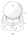
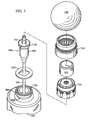
- Figs. 1-3 illustrate a first embodiment of the present invention which consists of a dispensing assembly 90 for mounting to a container or receptacle 100.
- the illustrated receptacle 100 is shown in one preferred form as a conventional, transparent, glass bottle suitable for containing a liquid perfume.
- the container 100 includes a neck 102 with an outwardly projecting rim, lip or flange 104 at its upper end.
- the top of the bottle flange 104 has an upwardly projecting, annular sealing bead 105 (see Figs. 3 and 19 ).
- a suitable dispensing module 106 such as previously discussed, includes a pump cartridge 108, a dip tube 110, and an upwardly biased stem 112 on which an external actuator button 114 is disposed.
- the dip tube 110 is illustrated in Figs. 1 and 2 as visible as would be the case with a transparent or translucent container 100). It will be appreciated by those skilled in the art that a user may press down on the button 114 in order to operate the pump cartridge 108 whereby fluid in the container 100 is pumped up through the dip tube 110 and stem 112 and dispensed as a fine mist spray out the opening in the actuator button 114.
- a gasket 120 (preferably molded from a plastic rubber), ferrule 122 and collar 124 function to secure the assembly to the container 100 as described in greater detail below.
- a removable dust cap or overcap 126 (see Figs. 2 and 3 ) is also provided for decorative design as well as to protect the actuator button 114 and prevent inadvertent dispensing of the product.
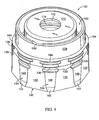
- the ferrule 122 of the first embodiment is illustrated in detail in Figs. 4-10 , and may be advantageously molded of a durable but somewhat resilient, plastic material (e.g ., polypropylene).
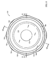
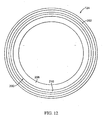
- the ferrule 122 includes a lower skirt 130 having an outer surface which is generally a regular polygon in cross-section, and in the illustrated embodiment is generally octagonal with eight generally flat surfaces 132 connected at eight outwardly projecting, somewhat cut-off corners 134 (see, e.g ., Figs. 7 and 8 ).
- the skirt 130 may advantageously be continuous, although it should be appreciated that a ferrule 122 in which the skirt 130 is slit, particularly in the flat surfaces 132, could also be used with the present invention.
- the outer surface of the skirt 130 at each of the corners 134 has, at the upper end, a lip 136 having an outer diameter ODC 1 with recessed area 138 beneath the lip 136.
- the bottom portion 142 of the skirt corners 134 are tapered outwardly at an angle A (see Fig. 9 ) whereby the outer diameter at the bottom ODC 4 is slightly greater than the outer diameter ODC 3 of the axially extending surface 140 thereabove.
- the flat surfaces 132 of the ferrule 122 between the corners 134 may be slightly tapered inwardly from top to bottom ( e.g ., by the angle B as illustrated in Fig. 10 , where the outer diameter at the top of the skirt ODF 1 is greater than the outer diameter at the bottom of the skirt ODF 2 owing to the taper angle B).
- the inner surface 150 of the skirt 130 is, by contrast, generally cylindrical (see Fig. 7 ) with elongated ribs or nibs 152 projecting inwardly therefrom.
- sets of three nibs 152 are provided at each corner 134, where each nib 152 includes a lower face 156 which tapers in toward the axial center of the ferrule 122 from the bottom at a point spaced above the bottom of the skirt 130, and includes a less tapered upper shoulder 158.
- the internal diameter of the ferrule122, the distance each nib 152 projects inwardly, and the heights of the nib surfaces 156 and 158 are determined by the size and type of bottle flange 104 on which the ferrule 122 is to be mounted.
- different bottle flange sizes are provided according to industry standards such as GPI and FEA.
- the exterior configuration and size of the ferrule 122 can be constant regardless of the interior size and configuration of the ferrule 122.
- the design of the exterior of the ferrule 122 and the design of the collar 124 can remain the same regardless of the type and size of the bottle on which the dispensing assembly is to be installed.
- the ferrule 122 includes a deck or downwardly facing shoulder 160 extending inwardly from the upper end of the skirt 130, which shoulder 160 is adapted for seating against the gasket 120 on the top of the container neck 102 (see Figs. 3 and 19 ) when assembled as further described below.
- the hardness of the material of the ferrule 122 desired to ensure that the ferrule 122 will be properly retained on the container neck 102 as described in detail herein will be such that a softer gasket 120 may be advantageously used as described and shown to ensure a proper seal:
- the gasket 120 may be omitted. Therefore, it should be recognized that it would be within the scope of the present invention to provide a ferrule 122 which itself has sufficient softness to provide a desired seal without inclusion of a separate gasket.
- a generally cylindrical turret or cap portion 170 ( Fig. 10 ) with a central opening 172 extends up from the ferrule shoulder 160 and includes a reduced diameter portion 174 on its inner surface.
- the pump cartridge 108 may be secured in the cap portion 170 with the flange 176 (see Figs. 3 and 19 ) of the cartridge 108 trapped above the reduced diameter portion 174 with the stem 112 extending through the central opening 172.
- a concentric outer lip 178 also extends up from the shoulder 160 and surrounds the cap portion 170 to define an annular space 180 therebetween, and a lower skirt on the actuator button 114 may be guided within the space 180, and protected, during reciprocating pumping movement of the actuator button 114 (see Fig. 19 ).
- An outer shoulder or lip 184 defining outwardly extending lips at the corners above the ferrule skirt 130 is also provided to facilitate assembly as described hereinafter.
- a notch 188 may also be provided in the upper end of the outer lip 178 to accommodate the mold gate for the injection of the thermoplastic resin during molding of the ferrule 122.
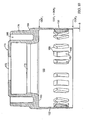
- the metal collar 124 of the embodiment of Figs. 1-3 is illustrated in Figs. 11-14 wherein, as best seen in Fig. 14 , the collar consists of two parts: an inner mounting collar 200 and an outer decorative collar 202 which is secured thereon. Both collars 200, 202 may be made from aluminum or other suitable materials.
- the collar 124 may in one form be a single annular metal piece, and in another form may be a subassembly, such as illustrated, of two separate pieces (200, 202) which are mechanically staked together to form a single, integral subassembly for mounting on the ferrule 122 in a process described in detail hereafter.
- the mounting collar 200 is generally cylindrical with an inwardly extending lip 206 at its upper end and a Nomar edge 210 at its lower end.
- a pair of spaced annular ridges 214, 216 extend around the mounting collar 200 above the decorative collar 202 to define a groove within which the cap 126 (see Figs. 2 and 3 ) may be snapped in order to be secured thereon (see Fig. 15 ).
- Also provided around the lower portion of the mounting collar 200 are a plurality of discrete ribs 220 which project inwardly from the inner surface of the collar 200 and extend generally axially but at an angle of, for example, about 15° ( ⁇ 5°) from the axial direction.
- the inner diameter of the mounting collar 200 between the annular ridges 214, 216 is ID 1 .
- the general inner diameter of the lower portion of the mounting collar 200 is ID 3 , with the ribs 220 projecting inwardly to an effective inner diameter (between two diametrically opposite ribs) of ID 2 .
- the Nomar edge 210 at the lower end of the mounting collar 200 consists of a thinned annular portion above a thickened bottom annular portion (formed by bending up the bottom edge of the thinner, lower portion of the collar).
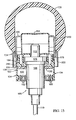
- Figs. 15-18 in which the above described components are illustrated as assembled but prior to mounting on a container 100.
- the components are in substantially the same relative orientation to one another that they will be when finally assembled on a container 100 except that the mounting collar 200 is snap fit in a raised position relative to the ferrule 122.
- the collar 124 In this raised (shipping) position, the collar 124 is only partially pushed onto the ferrule 122 with the bottom (Nomar) edge, at the corners 134, secured to the ferrule 122 between the lip 136 and the outer lip 184 (see Fig. 9 ) as seen in Figs. 15 and 16 .
- the lower end of the mounting collar 200 may be spaced from the outer surface of the ferrule 122 as shown in Figs. 17 and 18 .
- the gasket 120 may be stretched to fit over the pump cartridge 108 whereby it is frictionally held thereon as illustrated.
- the ferrule 122 is pushed down over the bottle neck 102 during initial assembly, at which time the nibs 152 are first forced outwardly (by compression of the nibs 152 and stretching of the skirt 130) in order to pass over the bottle flange 104 at the upper end of the bottle neck 102.
- the size of the bottle flange 104 may vary for different bottles 100 and may also vary due to manufacturing tolerances, the compression of the gasket 120, and the elasticity of the ferrule skirt 130 and nibs 152 cause the nibs 152 to move radially inwardly under the bottle flange 104 at the end of the initial phase of the mounting process.
- the mounting process may be effected entirely by automated equipment or partly manually. In either case, the process begins with the assembled components (as in Figs. 15-18 ) provided to a bottler (typically, however, without the cap 126 thereon during mounting). If a partially manual process is employed to mount the dispensing assembly 90 on the container 100, then the ferrule 122 (with gasket 120, dispensing module 106; and initially positioned collar 124) are manually pushed onto the neck of a filled container 100 (such as a bottle) at a first work station. During this step, the collar 124 does not move relative to the ferrule 122 so that the collar 124 remains in the "up" position between the ferrule lips 184 and 136 as shown in Fig. 15 .
- the ferrule 122 and collar 124 thus move downwardly together on the bottle flange 104.
- the snap-fit engagement of the ferrule 122 with the bottle neck flange 104 maintains the assembly 90 in position on the bottle 100 while the bottle 100 is moved to a second work station at which a mechanical plunger device is operated to hold the bottle 100 and push the metal collar 124 all the way down on the ferrule 122.
- a mechanical plunger device is operated to hold the bottle 100 and push the metal collar 124 all the way down on the ferrule 122.
- portions of the ferrule 122 are compressed and deformed inwardly (and, to a small extent, the collar 124 may stretch radially outwardly) as a tight, interference fit is established.
- the assembly of the gasket 120, dispensing module 106, ferrule 122, and collar 124 may be pushed down on the bottle 100 in one continuous motion by a spindle.
- the spindle exerts an initial force (e.g., 30 to 40 pounds) on the top of the collar 124 so that the collar 124 and ferrule 122 move together until the bottom of the ferrule 122 initially snaps down over the bottle flange 104 and can be pushed down no further as previously described.
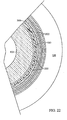
- the spindle then exerts a greater force (e.g ., 40 to 80 pounds) in the final phase of mounting so that the collar 124 is then moved all the way down relative to the ferrule 122 so as to completely surround the exterior side of the ferrule 122 as shown in Figs. 19-24 and further described below.
- a greater force e.g . 40 to 80 pounds
- the bottom of the Nomar edge 210 of the collar 124 initially pushes down on the lip 136 at the corners 134 of the skirt 130, distorting the lip 136 and pushing its material down around the outside of the skirt.
- the recessed area 138 beneath the lip 136 provides a space into which the lip material can be deformed so that, once a sufficient force is applied to the collar 124 during mounting to distort the lip 136 and begin moving the collar 124 down over the ferrule 122 as desired, the deformed material of the lip 136 will thereafter provide little hindrance to the collar 124 as the collar 124 continues to be pushed over the ferrule 122.
- the collar 124 can be pushed down with a sufficient, but not excessive, vertical installation force (e.g. , less than 100 pounds, such as 80 pounds in one proposed commercial design) which will not risk damaging the collar 124 or container 100 in the process.
- a sufficient, but not excessive, vertical installation force e.g. , less than 100 pounds, such as 80 pounds in one proposed commercial design
- the collar 124 As the collar 124 continues to be pushed down over the ferrule 122 during the final mounting phase, it squeezes the outer surface of the ferrule 122 inwardly against the radial outward surface of the bottle flange 104. While this will involve some squeezing inwardly of the nibs 152 to a position which is further under the bottle flange 104 compared to the initial phase of the mounting, the nibs 152 are already generally under the bottle flange 104 after the initial mounting phase as previously described.
- the collar 124 has been pushed all the way down over the ferrule 122 so that the Nomar edge 210 is beneath the bottom edge of the ferrule skirt 130, with the skirt elastically expanded outwardly so that it is above the upwardly facing shoulder 224 of the Nomar edge 210.
- the nibs 152 are secured by the surrounding substantially rigid collar 124 underneath the bottle flange 104 whereby the mounted dispensing assembly 90 is securely retained on the bottle neck 102. While some buckling of the flat surfaces 132 of the ferrule skirt 130 may result in portions of the skirt 130 being positioned below the bottle flange 104, it is the nibs 152 which substantially retain the assembly 90 on the bottle neck 102.
- the ribs 220 on the inner surface of the collar 124 will also secure the collar 124 on the ferrule 122, as the ribs 220 press into the outer surface of the ferrule skirt 130 (at least at the corners 134), providing not only a friction connection but also, due to their slight angle relative to the axial direction, an interference against the collar 124 being pulled axially off the ferrule 122.
- such angled orientation of the ribs 220 enables the ribs 220 to be slid down relatively easily (and possibly slightly “screwed on") during the final phase of the mounting process without requiring that an undesirably excessive mounting force be applied to the collar 124. Once fully mounted, cold flow or creep of the plastic material of the ferrule 122 around the ribs 220 will further facilitate long term holding of the collar 124 on the ferrule 122.
- a ferrule 122 and collar 124 combination such as described above for mounting on a conventional glass bottle 100 (e.g., FEA design) having a flange 104 with a nominal outside diameter which is (a) greater than an effective inner diameter between two diametrically opposite ferrule nibs 152 of 14.70 mm ⁇ 0.20 and (b) no greater than an inside diameter of the ferrule skirt 150 of 15.60 mm ⁇ 0.13, for example, a bottle neck 104 having a nominal outside diameter of 15 mm:
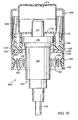
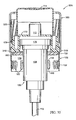
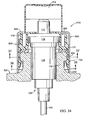
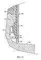
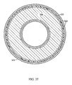
- Figs. 25-39 illustrate an alternate embodiment of a dispensing module 90A also incorporating aspects of the present invention.
- the components may be the same as in the first described embodiment except that a different collar 300 is used, without an overcap. Accordingly, the same reference numerals are used in the Figs. 25-39 as used to describe the same components in Figs. 1-24 and repetition of the details of those same components will not be made here.
- comparable elements will be identified by comparable reference numbers as used in Figs. 1-24 but with 100 added (e.g ., the ribs 220 in Fig. 14 are identified as ribs 320 where appropriate in Figs. 25-39 ).
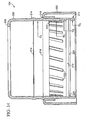
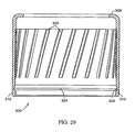
- the modified metal collar 300 is shown in particular in Figs. 26-29 , and is essentially simplified from the collar 124 of the first embodiment by providing a substantially cylindrical outer surface without annular ridges for mounting an overcap.
- This simpler configuration (with a longer straight cylindrical portion) provides a smooth aesthetic appearance to the entire collar 300 (which is not covered by an overcap), and also permits the internal ribs 320 to be longer as well (see Fig. 29 ).
- the friction between the ribs 320 and the ferrule 122 may be increased, as may the interference against axially pulling the fully mounted collar 300 off the ferrule 122, even though the ribs 320 extend up above the engaged outer surface of the ferrule 122 and therefore at their upper end are not enclosed by creep of the ferrule 122.
- this design may permit the collar 300 to be more readily twisted and pulled off if necessary for some unusual reason, such removal would still not be easy given the interference between the bottom of the ferrule skirt and the collar Nomar edge 310.
- the present invention permits easy and reliable assembly of a dispenser assembly 90, and further permits easy and reliable mounting of the assembly 90 on a container 100. Moreover, the present invention significantly reduces the likelihood that the dispenser assembly 90 will inadvertently or undesirably become decoupled from the container 100. In particular, the assembly 90 can be properly installed without requiring an excessive installation force - yet the installed configuration provides a greatly increased resistance to removal (owing significantly to the interference between the bottom of the ferrule corners 134 and the Nomar edge shoulders 224, 324 ( Figs. 20 and 35 )).
Landscapes
- Containers And Packaging Bodies Having A Special Means To Remove Contents (AREA)
- Closures For Containers (AREA)
- Infusion, Injection, And Reservoir Apparatuses (AREA)
- Loading And Unloading Of Fuel Tanks Or Ships (AREA)
Claims (15)
- Komponenten für eine Abgabeanordnung (90) zum Abgeben einer Substanz aus einem Behälter (100), wobei der Behälter (100) einen Hals (102) und einen Flansch (104) umfasst, wobei die Komponenten der Abgabeanordnung Folgendes umfassen:- einer Druckhülse (122), die ausgebildet ist, um eine Kopplung eines Abgabemoduls (106) an den Behälter (100) aufrecht zu erhalten, wobei die Druckhülse (122) Folgendes umfasst:- ein Schulterteil (160), welches an das Abgabemodul (106) fixierbar ist,- eine Schürze (130), die im Allgemeinen ringförmig um eine Achse ausgebildet ist und eine axiale Öffnung an einem ihrer Enden definiert, wobei das Abgabemodul (106) durch die Öffnung sich hindurch erstreckt, wenn es an dem Schulterteil (160) befestigt ist, und- Nasen (152), die sich von einer inneren Oberfläche (150) der Schürze (130) hin zu der Achse erstrecken, wobei die Schürze (130) und die Nasen (152) biegsam sind;- einen im Wesentlichen festen ringförmigen Bund (124) mit einer im Allgemeinen ringförmigen inneren Oberfläche, die ausgebildet ist, um über der äußeren Oberfläche der Schürze der Druckhülse angeordnet zu sein, wenn die Druckhülse (122) auf dem Behälter (100) befestigt ist, wobei der Bund (124) an einem Ende geöffnet ist und einen nach innen gerichteten ringförmigen Flansch (206) an seinem anderen Ende aufweist, und der Bund an der Innenoberfläche eine ringförmige Ausnehmung bei dem offenen Ende umfasst und eine ringförmige Oberseite (224) definiert, die dem anderen Ende des Bundes zugewandt ist; wobei- das offene eine Ende der Schürze (130) der Druckhülse radial nach außen in die ringförmige Ausnehmung der inneren Oberfläche des Bundes sich erstreckt, wenn die Abgabeanordnung (90) auf dem Behälter (100) befestigt ist,- die Schürze (130) kontinuierlich ist, wobei die Schürze (130) eine äußere Oberfläche aufweist, die in einer Ebene senkrecht zu der Achse im Wesentlichen in Form eines regulären Polygons mit flachen Oberflächen (132) zwischen den Ecken (134) gestaltet ist, dadurch gekennzeichnet, dass- die ringförmige Ausnehmung zu dem offenen Ende des Bundes hin nach außen konisch verlaufend ist, und die Komponenten weiter zumindest Abschnitte der äußeren Oberfläche der Schürze der Druckhülse umfassen, die konisch nach außen verlaufend ausgebildet sind, wobei sich die äußeren Oberflächenabschnitte der Schürze der Druckhülse in die ringförmige Ausnehmung des Bundes erstrecken, wenn die Abgabeanordnung (90) auf dem Behälter (100) befestigt ist.
- Komponenten einer Abgabeanordnung nach Anspruch 1, weiter umfassend ein Abgabemodul (106), welches an der Druckhülse (122) befestigt ist.
- Komponenten einer Abgabeanordnung nach Anspruch 1, wobei der Bund (124) einen Nomar-Rand (210) umfasst, welcher an dem offenen Ende angeordnet ist und die Ausnehmung und die ringförmige Oberseite (224) definiert.
- Komponenten einer Abgabeanordnung nach Anspruch 1, die weiter langgestreckte Rippen (220) aufweist, die sich nach innen von der Innenoberfläche des Bundes erstrecken.
- Komponenten einer Abgabeanordnung nach Anspruch 4, wobei die Rippen (220) entlang der inneren Oberfläche des Bundes (124) abgewinkelt sind.
- Komponenten einer Abgabeanordnung nach Anspruch 5, wobei jede Rippe (220) einen Winkel von ungefähr 5 bis 15° auf der Innenseite des Bundes (124) relativ zu der Achse bildet.
- Komponenten einer Abgabeanordnung nach Anspruch 1, wobei die Ecken (134) der Schürze (130) abgerundet sind.
- Komponenten einer Abgabeanordnung nach Anspruch 1, wobei die Ecken (134) der äußeren Oberfläche der Schürze der Druckhülse in die ringförmige Ausnehmung des Bundes sich erstrecken, wenn die Abgabeanordnung (90) auf dem Behälter (100) befestigt ist.
- Komponenten einer Abgabeanordnung nach Anspruch 1, wobei der Radius der Ecken der Druckhülse (134) von der Achse X ist, und der Radius der inneren Oberfläche des Bundes Z ist, wobei X > Z vor dem Befestigen des Bundes (124) auf dem Druckhülse (122).
- Komponenten einer Abgabeanordnung nach Anspruch 9, wobei der Radius am Mittelpunkt der flachen Oberflächen der Druckhülse von der Achse Y ist, wobei Y < Z.
- Komponenten einer Abgabeanordnung nach Anspruch 1, wobei der Radius am Mittelpunkt der flachen Oberflächen (132) von der Achse Y ist, und der Radius der inneren Oberfläche des Bundes Z ist, wobei Y < Z.
- Komponenten einer Abgabeanordnung nach Anspruch 1, wobei der Bund aus Aluminium gefertigt ist.
- Komponenten einer Abgabeanordnung nach Anspruch 1, die weiter einen Randabschluss (136) auf der äußeren Oberfläche der Druckhülse benachbart zu dem anderen Ende der Schürze (130) der Druckhülse umfasst und eine Ausnehmung (138) unterhalb des Randabschlusses (136) umfasst, wobei der Randabschluss (136) sich bis auf einen Durchmesser erstreckt, der größer ist als der Durchmesser des einen Endes des Bundes.
- Verfahren zum Befestigen von Komponenten einer Abgabeanordnung nach Anspruch 1 auf einen Behälter (100) mit einem Hals (102) und einem Flansch (104), dadurch gekennzeichnet, dass folgende Schritte umfasst sind:Anordnen einer Druckhülse (122) auf dem Behälterflansch (104), so dass sich das Abgabemodul (90) in den Behälter (100) hinein erstreckt;Drücken der Druckhülse (122) über den Behälterflansch (104), um Nasen (152) der Druckhülse unterhalb des Behälterflansches (104) anzuordnen; undDrücken des Bundes (124) über die Schürze (130) der Druckhülse, um die Nasen (152) unterhalb des Flansches einzuklemmen.
- Verfahren nach Anspruch 14, welches weiter Folgendes umfasst: Bereitstellen eines Randabschlusses (136) auf der Druckhülse (122) mit einer Ausnehmung (138) unterhalb des Randabschlusses (136), wobei:der Schritt des Anordnens ein Halten des Bundes (124) auf dem Randabschluss (136) der Druckhülse umfasst;der Schritt des Drückens der Druckhülse ein Drücken des Bundes (124) umfasst,während der Bund (124) auf dem Randabschluss (136) der Druckhülse angeordnet wird, um den Bund (124) als auch die Druckhülse (122) relativ zu dem Flansch des Behälters (104) zu bewegen; undder Schritt des Drückens des Bundes ein Drücken des Bundes (124) relativ zu der Druckhülse (122) umfasst, um das Material des Randabschlusses (136) der Druckhülse in die Ausnehmung (138) unterhalb des Randabschlusses (136) zu drücken.
Priority Applications (1)
| Application Number | Priority Date | Filing Date | Title |
|---|---|---|---|
| EP12176560.6A EP2514532B1 (de) | 2006-09-06 | 2007-09-04 | Spenderanordnung für einen Flüssigkeitsspenderbehälter und Montageverfahren dafür |
Applications Claiming Priority (1)
| Application Number | Priority Date | Filing Date | Title |
|---|---|---|---|
| US11/516,276 US7757902B2 (en) | 2006-09-06 | 2006-09-06 | Dispenser assembly for a fluid dispensing receptacle and method of assembling same |
Related Child Applications (2)
| Application Number | Title | Priority Date | Filing Date |
|---|---|---|---|
| EP12176560.6A Division EP2514532B1 (de) | 2006-09-06 | 2007-09-04 | Spenderanordnung für einen Flüssigkeitsspenderbehälter und Montageverfahren dafür |
| EP12176560.6 Division-Into | 2012-07-16 |
Publications (3)
| Publication Number | Publication Date |
|---|---|
| EP1897623A2 EP1897623A2 (de) | 2008-03-12 |
| EP1897623A3 EP1897623A3 (de) | 2009-07-08 |
| EP1897623B1 true EP1897623B1 (de) | 2012-11-07 |
Family
ID=38663575
Family Applications (2)
| Application Number | Title | Priority Date | Filing Date |
|---|---|---|---|
| EP07017311A Active EP1897623B1 (de) | 2006-09-06 | 2007-09-04 | Spenderanordnung für einen Flüssigkeitsspenderbehälter und Montageverfahren dafür |
| EP12176560.6A Not-in-force EP2514532B1 (de) | 2006-09-06 | 2007-09-04 | Spenderanordnung für einen Flüssigkeitsspenderbehälter und Montageverfahren dafür |
Family Applications After (1)
| Application Number | Title | Priority Date | Filing Date |
|---|---|---|---|
| EP12176560.6A Not-in-force EP2514532B1 (de) | 2006-09-06 | 2007-09-04 | Spenderanordnung für einen Flüssigkeitsspenderbehälter und Montageverfahren dafür |
Country Status (3)
| Country | Link |
|---|---|
| US (2) | US7757902B2 (de) |
| EP (2) | EP1897623B1 (de) |
| ES (2) | ES2519840T3 (de) |
Families Citing this family (25)
| Publication number | Priority date | Publication date | Assignee | Title |
|---|---|---|---|---|
| FR2891530B1 (fr) * | 2005-10-04 | 2007-12-07 | Valois Sas | Organe de recouvrement, procede de fabrication d'un tel organe et distributeur de produit fluide utlisant un tel organe. |
| FR2891533B1 (fr) * | 2005-10-04 | 2007-12-07 | Valois Sas | Organe de recouvrement, procede de fabrication d'un tel organe et distributeur de produit fluide utilisant un tel organe. |
| FR2891529B1 (fr) * | 2005-10-04 | 2007-12-07 | Valois Sas | Organe de recouvrement, procede de fabrication d'un tel organe et distributeur comprenant un tel organe. |
| US20090014679A1 (en) * | 2007-07-13 | 2009-01-15 | Precision Valve Corporation | Plastic aerosol valve and method of assembly, mounting and retention |
| USD636668S1 (en) * | 2008-03-24 | 2011-04-26 | Mary Kay Inc. | Dip tubes |
| EP2279044A1 (de) * | 2008-05-19 | 2011-02-02 | MeadWestvaco Corporation | Pumpenhaltering und verfahren zu seiner verwendung |
| FR2948344B1 (fr) * | 2009-07-27 | 2011-09-02 | Valois Sas | Systeme de fixation demontable. |
| WO2011116201A2 (en) * | 2010-03-18 | 2011-09-22 | Meadwestvaco Calmar, Inc. | Pump and bottle fitments and methods for using the same |
| FR2957900B1 (fr) * | 2010-03-25 | 2012-05-11 | Rexam Dispensing Sys | Systeme de fixation d'un organe de distribution d'un produit fluide sur le col d'un flacon |
| FR2961192B1 (fr) * | 2010-06-10 | 2012-07-27 | Rexam Healthcare La Verpillier | Dispositif de distribution de produit comprenant une pompe et un embout de distribution |
| US9296550B2 (en) | 2013-10-23 | 2016-03-29 | The Procter & Gamble Company | Recyclable plastic aerosol dispenser |
| US11814239B2 (en) | 2011-05-16 | 2023-11-14 | The Procter & Gamble Company | Heating of products in an aerosol dispenser and aerosol dispenser containing such heated products |
| FR2975675B1 (fr) * | 2011-05-23 | 2014-06-06 | Valois Sas | Organe de fixation et distributeur comprenant un tel organe. |
| US20140263479A1 (en) * | 2013-03-14 | 2014-09-18 | Inoac Packaging Group, Inc. | Cap for a container |
| US20150060415A1 (en) * | 2013-08-26 | 2015-03-05 | Nelson Stud Welding, Inc. | Method of Welding a Stud To a Work Piece, and a Thermal Stud Welding Ferrule For Same |
| USD794450S1 (en) * | 2014-06-19 | 2017-08-15 | Aptar France Sas | Dispenser |
| US20170095757A1 (en) | 2015-05-27 | 2017-04-06 | Flow Control LLC | Cartridge Accumulator |
| US11020695B2 (en) | 2015-05-27 | 2021-06-01 | Flow Control LLC | Cartridge pump |
| JP7049991B2 (ja) | 2015-09-14 | 2022-04-07 | フロー コントロール リミティド ライアビリティ カンパニー | カートリッジアキュムレータ |
| US10526133B2 (en) | 2017-02-28 | 2020-01-07 | The Procter & Gamble Company | Aerosol dispenser having a safety valve |
| WO2020041792A1 (en) | 2018-08-24 | 2020-02-27 | Clayton Corporation | Plastic mounting cup and valve for pressurized container |
| EP4113114B1 (de) * | 2019-05-15 | 2025-06-25 | Waters Technologies Corporation | Vorrichtung zur hochdruckabdichtung |
| US11407000B2 (en) | 2019-09-23 | 2022-08-09 | S. C. Johnson & Son, Inc. | Volatile material dispenser |
| FR3110150B1 (fr) * | 2020-05-15 | 2022-06-10 | Pm France Packaging | Habillage de pompe |
| USD1027642S1 (en) * | 2021-12-24 | 2024-05-21 | Yonwoo Co., Ltd. | Packaging pump container |
Family Cites Families (26)
| Publication number | Priority date | Publication date | Assignee | Title |
|---|---|---|---|---|
| US722642A (en) | 1902-01-17 | 1903-03-10 | Joshua W Sykes | Carpet-sweeper. |
| GB722642A (en) | 1952-10-24 | 1955-01-26 | Inter Seal Corp | Improvements in bottle closures |
| US2723773A (en) | 1952-10-24 | 1955-11-15 | Interseal Corp | Bottle closures |
| US3112048A (en) * | 1961-06-08 | 1963-11-26 | Virjune Mfg Co Inc | Decorative ring and flexible insert for spray container |
| NO132792C (de) | 1973-09-07 | 1976-01-07 | Nordpremium As | |
| US4073398A (en) | 1977-01-28 | 1978-02-14 | The Risdon Manufacturing Company | Snap-lock device for securing a dispensing mechanism to a container |
| DE2813940A1 (de) | 1977-04-23 | 1978-10-26 | Zensho Honma | Flaschenverschluss |
| US4251003A (en) | 1979-01-19 | 1981-02-17 | Toni Casutt | Bottle closing device |
| US4284211A (en) * | 1979-09-26 | 1981-08-18 | Emson Research, Inc. | Nibbed ferrule for holding cap |
| CH643201A5 (de) | 1979-11-07 | 1984-05-30 | Createchnic Patent Ag | Verschlusskappe und verfahren zu ihrer herstellung. |
| US4773553A (en) | 1985-09-12 | 1988-09-27 | Risdon Corporation | Assembly for securing and sealing a dispenser to a flanged container |
| FR2651837B1 (fr) | 1989-09-08 | 1993-04-23 | Aerosol Inventions Dev | Pompe manuelle pre-orientable sur le goulot d'un recipient. |
| US5192006A (en) | 1991-05-01 | 1993-03-09 | Risdon Corporation | Low profile pump |
| US5348174A (en) | 1993-01-14 | 1994-09-20 | Eyelematic Manufacturing Co., Inc. | Metal flexible finger ferrule for flanged container closure |
| US5299703A (en) * | 1993-06-30 | 1994-04-05 | American Dispensing Systems Inc. | Device for securing a dispenser to a glass container |
| DE4342680A1 (de) | 1993-12-15 | 1995-06-22 | Pfeiffer Erich Gmbh & Co Kg | Austragvorrichtung für Medien |
| US5562219A (en) * | 1994-09-22 | 1996-10-08 | Valois, S.A. | Device for attaching a dispenser member to a receptacle |
| EP0707895B1 (de) | 1994-10-17 | 1998-12-16 | SAR S.p.A. | Hülse zur Befestigung eines durch Hand zu betätigenden Pumpenaggregates auf eine Glasflasche |
| FR2760725B1 (fr) | 1997-03-14 | 1999-05-28 | Teleplastics Ind | Dispositif distributeur pour produits fluides |
| FR2769860B1 (fr) | 1997-10-16 | 2000-01-21 | Sofab | Dispositif pour l'assemblage d'une pompe sur un recipient |
| IT1302351B1 (it) * | 1998-10-01 | 2000-09-05 | Cml Costr Mecc Liri Srl | Macchina attorcigliatrice di pezzi allungati a sezione poligonale. |
| US6253941B1 (en) | 1999-01-19 | 2001-07-03 | Crown Cork & Seal Technologies Corporation | Assembly for securing and sealing a dispenser to a flanged container |
| BR0009237B1 (pt) * | 1999-03-23 | 2011-01-25 | dispositivo para o fechamento de garrafas. | |
| FR2820123B1 (fr) | 2001-01-30 | 2003-05-02 | Valois Sa | Dispositif de fixation d'organe de distribution sur un col de recipient |
| ES2187341B1 (es) * | 2001-02-28 | 2004-08-16 | Saint-Gobain Calmar S.A. | Capsula de un dispositivo para el cierre de una botella. |
| US6776311B2 (en) | 2002-11-13 | 2004-08-17 | Emsar, Incorporated | Dispenser assembly for a fragrance or personal care bottle and a method of assembling same |
-
2006
- 2006-09-06 US US11/516,276 patent/US7757902B2/en not_active Expired - Fee Related
-
2007
- 2007-09-04 ES ES12176560.6T patent/ES2519840T3/es active Active
- 2007-09-04 ES ES07017311T patent/ES2397369T3/es active Active
- 2007-09-04 EP EP07017311A patent/EP1897623B1/de active Active
- 2007-09-04 EP EP12176560.6A patent/EP2514532B1/de not_active Not-in-force
-
2010
- 2010-07-20 US US12/839,494 patent/US8061567B2/en active Active
Also Published As
| Publication number | Publication date |
|---|---|
| ES2519840T3 (es) | 2014-11-07 |
| EP2514532B1 (de) | 2014-08-20 |
| ES2397369T3 (es) | 2013-03-06 |
| US8061567B2 (en) | 2011-11-22 |
| US20080053948A1 (en) | 2008-03-06 |
| EP1897623A2 (de) | 2008-03-12 |
| EP2514532A1 (de) | 2012-10-24 |
| EP1897623A3 (de) | 2009-07-08 |
| US20100282782A1 (en) | 2010-11-11 |
| US7757902B2 (en) | 2010-07-20 |
Similar Documents
| Publication | Publication Date | Title |
|---|---|---|
| EP2514532B1 (de) | Spenderanordnung für einen Flüssigkeitsspenderbehälter und Montageverfahren dafür | |
| US5341956A (en) | Method for assembling a dispensing container | |
| US6695171B2 (en) | Pump dispenser | |
| US6073805A (en) | Assembly for packaging and dispensing a liquid product | |
| US3698595A (en) | Pressurized dispenser | |
| US4773553A (en) | Assembly for securing and sealing a dispenser to a flanged container | |
| US20020027146A1 (en) | Dispenser containing a product and dispensing method | |
| US4311255A (en) | Hand held container and dispenser assembly | |
| US5950880A (en) | Set of components for assembly as a dispensing package of the non-vented type having a take-up piston | |
| US6318595B1 (en) | Finger-actuatable spray pump package with user-ready two-piece spray-through cap, pre-assembly cap, and method for making said package | |
| KR102427023B1 (ko) | 액체 분사를 위한 펌프 | |
| KR102385639B1 (ko) | 화장품 용기 | |
| US20040222242A1 (en) | Dispenser assembly for a fragrance or personal care bottle and a method of assembling same | |
| EP3426411B1 (de) | Spenderpumpe | |
| US11453022B2 (en) | Container for fluid product | |
| KR20220045542A (ko) | 화장품 용기 | |
| WO1988002297A1 (en) | An assembly and method for securing and sealing a dispenser to a flanged container | |
| KR20220045581A (ko) | 액체 분사를 위한 용기 | |
| KR20210124741A (ko) | 펌프캡 | |
| US3957178A (en) | Hand-held dispenser pump construction | |
| KR20210136235A (ko) | 가변 배출 펌프 | |
| US6415989B1 (en) | Dispensing head for varying sizes of dispensing members | |
| US7073733B2 (en) | Microdispensing pump | |
| US20040069811A1 (en) | Fixing member for fixing a dispensing member to an opening of a reservoir, and a dispenser including such a fixing member | |
| EP1539616B1 (de) | Pfropfenartige pumpe |
Legal Events
| Date | Code | Title | Description |
|---|---|---|---|
| PUAI | Public reference made under article 153(3) epc to a published international application that has entered the european phase |
Free format text: ORIGINAL CODE: 0009012 |
|
| AK | Designated contracting states |
Kind code of ref document: A2 Designated state(s): AT BE BG CH CY CZ DE DK EE ES FI FR GB GR HU IE IS IT LI LT LU LV MC MT NL PL PT RO SE SI SK TR |
|
| AX | Request for extension of the european patent |
Extension state: AL BA HR MK YU |
|
| PUAL | Search report despatched |
Free format text: ORIGINAL CODE: 0009013 |
|
| AK | Designated contracting states |
Kind code of ref document: A3 Designated state(s): AT BE BG CH CY CZ DE DK EE ES FI FR GB GR HU IE IS IT LI LT LU LV MC MT NL PL PT RO SE SI SK TR |
|
| AX | Request for extension of the european patent |
Extension state: AL BA HR MK RS |
|
| 17P | Request for examination filed |
Effective date: 20100108 |
|
| AKX | Designation fees paid |
Designated state(s): AT BE BG CH CY CZ DE DK EE ES FI FR GB GR HU IE IS IT LI LT LU LV MC MT NL PL PT RO SE SI SK TR |
|
| 17Q | First examination report despatched |
Effective date: 20101001 |
|
| GRAP | Despatch of communication of intention to grant a patent |
Free format text: ORIGINAL CODE: EPIDOSNIGR1 |
|
| GRAS | Grant fee paid |
Free format text: ORIGINAL CODE: EPIDOSNIGR3 |
|
| GRAA | (expected) grant |
Free format text: ORIGINAL CODE: 0009210 |
|
| RAP1 | Party data changed (applicant data changed or rights of an application transferred) |
Owner name: APTARGROUP, INC. |
|
| AK | Designated contracting states |
Kind code of ref document: B1 Designated state(s): AT BE BG CH CY CZ DE DK EE ES FI FR GB GR HU IE IS IT LI LT LU LV MC MT NL PL PT RO SE SI SK TR |
|
| REG | Reference to a national code |
Ref country code: GB Ref legal event code: FG4D |
|
| REG | Reference to a national code |
Ref country code: CH Ref legal event code: EP Ref country code: AT Ref legal event code: REF Ref document number: 582761 Country of ref document: AT Kind code of ref document: T Effective date: 20121115 |
|
| REG | Reference to a national code |
Ref country code: IE Ref legal event code: FG4D |
|
| REG | Reference to a national code |
Ref country code: DE Ref legal event code: R096 Ref document number: 602007026487 Country of ref document: DE Effective date: 20130103 |
|
| REG | Reference to a national code |
Ref country code: ES Ref legal event code: FG2A Ref document number: 2397369 Country of ref document: ES Kind code of ref document: T3 Effective date: 20130306 |
|
| REG | Reference to a national code |
Ref country code: AT Ref legal event code: MK05 Ref document number: 582761 Country of ref document: AT Kind code of ref document: T Effective date: 20121107 |
|
| REG | Reference to a national code |
Ref country code: NL Ref legal event code: VDEP Effective date: 20121107 |
|
| REG | Reference to a national code |
Ref country code: LT Ref legal event code: MG4D |
|
| PG25 | Lapsed in a contracting state [announced via postgrant information from national office to epo] |
Ref country code: NL Free format text: LAPSE BECAUSE OF FAILURE TO SUBMIT A TRANSLATION OF THE DESCRIPTION OR TO PAY THE FEE WITHIN THE PRESCRIBED TIME-LIMIT Effective date: 20121107 Ref country code: SE Free format text: LAPSE BECAUSE OF FAILURE TO SUBMIT A TRANSLATION OF THE DESCRIPTION OR TO PAY THE FEE WITHIN THE PRESCRIBED TIME-LIMIT Effective date: 20121107 Ref country code: IS Free format text: LAPSE BECAUSE OF FAILURE TO SUBMIT A TRANSLATION OF THE DESCRIPTION OR TO PAY THE FEE WITHIN THE PRESCRIBED TIME-LIMIT Effective date: 20130307 Ref country code: LT Free format text: LAPSE BECAUSE OF FAILURE TO SUBMIT A TRANSLATION OF THE DESCRIPTION OR TO PAY THE FEE WITHIN THE PRESCRIBED TIME-LIMIT Effective date: 20121107 Ref country code: FI Free format text: LAPSE BECAUSE OF FAILURE TO SUBMIT A TRANSLATION OF THE DESCRIPTION OR TO PAY THE FEE WITHIN THE PRESCRIBED TIME-LIMIT Effective date: 20121107 |
|
| PG25 | Lapsed in a contracting state [announced via postgrant information from national office to epo] |
Ref country code: LV Free format text: LAPSE BECAUSE OF FAILURE TO SUBMIT A TRANSLATION OF THE DESCRIPTION OR TO PAY THE FEE WITHIN THE PRESCRIBED TIME-LIMIT Effective date: 20121107 Ref country code: GR Free format text: LAPSE BECAUSE OF FAILURE TO SUBMIT A TRANSLATION OF THE DESCRIPTION OR TO PAY THE FEE WITHIN THE PRESCRIBED TIME-LIMIT Effective date: 20130208 Ref country code: PT Free format text: LAPSE BECAUSE OF FAILURE TO SUBMIT A TRANSLATION OF THE DESCRIPTION OR TO PAY THE FEE WITHIN THE PRESCRIBED TIME-LIMIT Effective date: 20130307 Ref country code: BE Free format text: LAPSE BECAUSE OF FAILURE TO SUBMIT A TRANSLATION OF THE DESCRIPTION OR TO PAY THE FEE WITHIN THE PRESCRIBED TIME-LIMIT Effective date: 20121107 Ref country code: SI Free format text: LAPSE BECAUSE OF FAILURE TO SUBMIT A TRANSLATION OF THE DESCRIPTION OR TO PAY THE FEE WITHIN THE PRESCRIBED TIME-LIMIT Effective date: 20121107 Ref country code: PL Free format text: LAPSE BECAUSE OF FAILURE TO SUBMIT A TRANSLATION OF THE DESCRIPTION OR TO PAY THE FEE WITHIN THE PRESCRIBED TIME-LIMIT Effective date: 20121107 |
|
| PG25 | Lapsed in a contracting state [announced via postgrant information from national office to epo] |
Ref country code: AT Free format text: LAPSE BECAUSE OF FAILURE TO SUBMIT A TRANSLATION OF THE DESCRIPTION OR TO PAY THE FEE WITHIN THE PRESCRIBED TIME-LIMIT Effective date: 20121107 |
|
| PG25 | Lapsed in a contracting state [announced via postgrant information from national office to epo] |
Ref country code: SK Free format text: LAPSE BECAUSE OF FAILURE TO SUBMIT A TRANSLATION OF THE DESCRIPTION OR TO PAY THE FEE WITHIN THE PRESCRIBED TIME-LIMIT Effective date: 20121107 Ref country code: DK Free format text: LAPSE BECAUSE OF FAILURE TO SUBMIT A TRANSLATION OF THE DESCRIPTION OR TO PAY THE FEE WITHIN THE PRESCRIBED TIME-LIMIT Effective date: 20121107 Ref country code: BG Free format text: LAPSE BECAUSE OF FAILURE TO SUBMIT A TRANSLATION OF THE DESCRIPTION OR TO PAY THE FEE WITHIN THE PRESCRIBED TIME-LIMIT Effective date: 20130207 Ref country code: EE Free format text: LAPSE BECAUSE OF FAILURE TO SUBMIT A TRANSLATION OF THE DESCRIPTION OR TO PAY THE FEE WITHIN THE PRESCRIBED TIME-LIMIT Effective date: 20121107 Ref country code: CZ Free format text: LAPSE BECAUSE OF FAILURE TO SUBMIT A TRANSLATION OF THE DESCRIPTION OR TO PAY THE FEE WITHIN THE PRESCRIBED TIME-LIMIT Effective date: 20121107 |
|
| PG25 | Lapsed in a contracting state [announced via postgrant information from national office to epo] |
Ref country code: RO Free format text: LAPSE BECAUSE OF FAILURE TO SUBMIT A TRANSLATION OF THE DESCRIPTION OR TO PAY THE FEE WITHIN THE PRESCRIBED TIME-LIMIT Effective date: 20121107 |
|
| PLBE | No opposition filed within time limit |
Free format text: ORIGINAL CODE: 0009261 |
|
| STAA | Information on the status of an ep patent application or granted ep patent |
Free format text: STATUS: NO OPPOSITION FILED WITHIN TIME LIMIT |
|
| 26N | No opposition filed |
Effective date: 20130808 |
|
| PG25 | Lapsed in a contracting state [announced via postgrant information from national office to epo] |
Ref country code: CY Free format text: LAPSE BECAUSE OF FAILURE TO SUBMIT A TRANSLATION OF THE DESCRIPTION OR TO PAY THE FEE WITHIN THE PRESCRIBED TIME-LIMIT Effective date: 20121107 |
|
| REG | Reference to a national code |
Ref country code: DE Ref legal event code: R097 Ref document number: 602007026487 Country of ref document: DE Effective date: 20130808 |
|
| PG25 | Lapsed in a contracting state [announced via postgrant information from national office to epo] |
Ref country code: MC Free format text: LAPSE BECAUSE OF FAILURE TO SUBMIT A TRANSLATION OF THE DESCRIPTION OR TO PAY THE FEE WITHIN THE PRESCRIBED TIME-LIMIT Effective date: 20121107 |
|
| REG | Reference to a national code |
Ref country code: CH Ref legal event code: PL |
|
| REG | Reference to a national code |
Ref country code: IE Ref legal event code: MM4A |
|
| PG25 | Lapsed in a contracting state [announced via postgrant information from national office to epo] |
Ref country code: CH Free format text: LAPSE BECAUSE OF NON-PAYMENT OF DUE FEES Effective date: 20130930 Ref country code: IE Free format text: LAPSE BECAUSE OF NON-PAYMENT OF DUE FEES Effective date: 20130904 Ref country code: LI Free format text: LAPSE BECAUSE OF NON-PAYMENT OF DUE FEES Effective date: 20130930 |
|
| PG25 | Lapsed in a contracting state [announced via postgrant information from national office to epo] |
Ref country code: MT Free format text: LAPSE BECAUSE OF FAILURE TO SUBMIT A TRANSLATION OF THE DESCRIPTION OR TO PAY THE FEE WITHIN THE PRESCRIBED TIME-LIMIT Effective date: 20121107 Ref country code: TR Free format text: LAPSE BECAUSE OF FAILURE TO SUBMIT A TRANSLATION OF THE DESCRIPTION OR TO PAY THE FEE WITHIN THE PRESCRIBED TIME-LIMIT Effective date: 20121107 |
|
| PG25 | Lapsed in a contracting state [announced via postgrant information from national office to epo] |
Ref country code: HU Free format text: LAPSE BECAUSE OF FAILURE TO SUBMIT A TRANSLATION OF THE DESCRIPTION OR TO PAY THE FEE WITHIN THE PRESCRIBED TIME-LIMIT; INVALID AB INITIO Effective date: 20070904 Ref country code: LU Free format text: LAPSE BECAUSE OF NON-PAYMENT OF DUE FEES Effective date: 20130904 |
|
| REG | Reference to a national code |
Ref country code: FR Ref legal event code: PLFP Year of fee payment: 10 |
|
| REG | Reference to a national code |
Ref country code: FR Ref legal event code: PLFP Year of fee payment: 11 |
|
| REG | Reference to a national code |
Ref country code: FR Ref legal event code: PLFP Year of fee payment: 12 |
|
| PGFP | Annual fee paid to national office [announced via postgrant information from national office to epo] |
Ref country code: GB Payment date: 20231127 Year of fee payment: 17 |
|
| PGFP | Annual fee paid to national office [announced via postgrant information from national office to epo] |
Ref country code: IT Payment date: 20231122 Year of fee payment: 17 Ref country code: DE Payment date: 20231129 Year of fee payment: 17 |
|
| REG | Reference to a national code |
Ref country code: DE Ref legal event code: R119 Ref document number: 602007026487 Country of ref document: DE |
|
| PGFP | Annual fee paid to national office [announced via postgrant information from national office to epo] |
Ref country code: ES Payment date: 20250303 Year of fee payment: 18 |
|
| PGFP | Annual fee paid to national office [announced via postgrant information from national office to epo] |
Ref country code: FR Payment date: 20250303 Year of fee payment: 18 |
|
| GBPC | Gb: european patent ceased through non-payment of renewal fee |
Effective date: 20240904 |
|
| PG25 | Lapsed in a contracting state [announced via postgrant information from national office to epo] |
Ref country code: DE Free format text: LAPSE BECAUSE OF NON-PAYMENT OF DUE FEES Effective date: 20250401 |
|
| PG25 | Lapsed in a contracting state [announced via postgrant information from national office to epo] |
Ref country code: GB Free format text: LAPSE BECAUSE OF NON-PAYMENT OF DUE FEES Effective date: 20240904 |
|
| PG25 | Lapsed in a contracting state [announced via postgrant information from national office to epo] |
Ref country code: IT Free format text: LAPSE BECAUSE OF NON-PAYMENT OF DUE FEES Effective date: 20240904 |
|
| PG25 | Lapsed in a contracting state [announced via postgrant information from national office to epo] |
Ref country code: FR Free format text: LAPSE BECAUSE OF NON-PAYMENT OF DUE FEES Effective date: 20250930 |