EP1897708B1 - Maschine zum Anbringen und Abnehmen von Reifen und Felgen für Fahrzeuge - Google Patents
Maschine zum Anbringen und Abnehmen von Reifen und Felgen für Fahrzeuge Download PDFInfo
- Publication number
- EP1897708B1 EP1897708B1 EP07017551A EP07017551A EP1897708B1 EP 1897708 B1 EP1897708 B1 EP 1897708B1 EP 07017551 A EP07017551 A EP 07017551A EP 07017551 A EP07017551 A EP 07017551A EP 1897708 B1 EP1897708 B1 EP 1897708B1
- Authority
- EP
- European Patent Office
- Prior art keywords
- machine according
- configuration
- tyre
- slide
- clamping
- Prior art date
- Legal status (The legal status is an assumption and is not a legal conclusion. Google has not performed a legal analysis and makes no representation as to the accuracy of the status listed.)
- Active
Links
Images


Classifications
-
- B—PERFORMING OPERATIONS; TRANSPORTING
- B60—VEHICLES IN GENERAL
- B60C—VEHICLE TYRES; TYRE INFLATION; TYRE CHANGING; CONNECTING VALVES TO INFLATABLE ELASTIC BODIES IN GENERAL; DEVICES OR ARRANGEMENTS RELATED TO TYRES
- B60C25/00—Apparatus or tools adapted for mounting, removing or inspecting tyres
- B60C25/01—Apparatus or tools adapted for mounting, removing or inspecting tyres for removing tyres from or mounting tyres on wheels
- B60C25/05—Machines
- B60C25/132—Machines for removing and mounting tyres
- B60C25/135—Machines for removing and mounting tyres having a tyre support or a tool, movable along wheel axis
- B60C25/138—Machines for removing and mounting tyres having a tyre support or a tool, movable along wheel axis with rotary motion of tool or tyre support
-
- B—PERFORMING OPERATIONS; TRANSPORTING
- B60—VEHICLES IN GENERAL
- B60C—VEHICLE TYRES; TYRE INFLATION; TYRE CHANGING; CONNECTING VALVES TO INFLATABLE ELASTIC BODIES IN GENERAL; DEVICES OR ARRANGEMENTS RELATED TO TYRES
- B60C25/00—Apparatus or tools adapted for mounting, removing or inspecting tyres
- B60C25/01—Apparatus or tools adapted for mounting, removing or inspecting tyres for removing tyres from or mounting tyres on wheels
- B60C25/05—Machines
- B60C25/0563—Tools interacting with the tyre and moved in relation to the tyre during operation
- B60C25/0578—Tools interacting with the tyre and moved in relation to the tyre during operation hooking only
-
- B—PERFORMING OPERATIONS; TRANSPORTING
- B60—VEHICLES IN GENERAL
- B60C—VEHICLE TYRES; TYRE INFLATION; TYRE CHANGING; CONNECTING VALVES TO INFLATABLE ELASTIC BODIES IN GENERAL; DEVICES OR ARRANGEMENTS RELATED TO TYRES
- B60C25/00—Apparatus or tools adapted for mounting, removing or inspecting tyres
- B60C25/01—Apparatus or tools adapted for mounting, removing or inspecting tyres for removing tyres from or mounting tyres on wheels
- B60C25/05—Machines
- B60C25/0518—Horizontal wheel axis in working position
Definitions
- the present invention refers to a machine for fitting and removing tyres and wheel rims for vehicles.
- the vehicle wheels generally comprise a metal rim having along the perimeter ring-shaped turn-ups between which the end portions, so-called “beads" of an elastic tyre, are inserted fast up and adherent.
- Such "tyre changing" machines can be, for example, of the automatic type and are essentially composed of a supporting frame for clamping and rotating means for clamping and rotating the rim of a wheel onto/from which the tyre must be fitted/removed and of an operating unit having an operating head for fitting and removing the tyre.
- Such operating head is, generally, equipped with a tool for fitting the tyre on the rim and with a tool for removing the tyre.
- the removing tool in particular, is arranged with substantially transversal direction with respect to the longitudinal axis of the operating head and has a curved end part which is turned towards the wheel to be removed during the course of the job.
- the removing tool is, generally, supported by the operating head and can be turned around a fixed axis between a configuration for pushing a side of the tyre and for clamping the corresponding bead and a configuration for entraining the tyre in a direction away from the relevant rim.
- the end part of this tool is brought up against a side of the tyre and pressed against this so as to move the tyre bead away from the relevant turn-up, so as to allow the tool to fasten onto the edge of the tyre for subsequent moving away from the rim.
- the operating head comprises a pushing body with a contact surface positionable against the side of a tyre and a tool for the removal of the tyre which is moving between a position in which it is housed inside the pushing body and a position in which it protrudes from the body to grip the tyre bead.
- the operating head is brought close to the tyre to be removed by means of a first actuator which operates horizontally, so that the contact surface of the pushing body comes up against the side of the tyre, moving it from the rim and creating a passage for the tool.
- the tool is then moved outside the pushing body and fitted between the tyre and the rim to grip the tyre bead.
- the operating head is moved away from the rim by the combined action of the first actuator and of a second actuator that operates vertically, so as to drag the tyre outside the rim.
- the known machine comprise also a tool provided with a bead detaching member and an engaging member for extracting the lyre from the rim, wherein the detaching member also operates as a member for removing/rising the tyre and the engaging member is movable from a retracted position to a projecting position in which it project at least partially from said bead-detaching member.
- the detaching member also operates as a member for removing/rising the tyre and the engaging member is movable from a retracted position to a projecting position in which it project at least partially from said bead-detaching member.
- the main aim of the present invention is to provide a machine for fitting and removing tyres and wheel rims for vehicles that allows achieving the above upgrading.
- another object of the present invention is to cater for the above aims with a simple structure, of relatively practical implementation, safe to use and with effective operation, as well as having a relatively low cost.
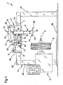
- the machine 1 comprises a supporting structure 2 for supporting clamping and rotating means 3 for clamping and rotating a rim A onto/from which to fit/remove a tyre B around a substantially horizontal rotation axis C.
- An operating unit 4 is supported moving by the structure 2 and is provided with an operating head 5 for fitting and/or removing the tyre B onto/from the rim A.
- the structure 2 comprises a base 2a from which elevate a first and a second upright 2b and 2c distance from each other and supporting a transom 2d arranged above the clamping and rotating means 3 and to which the operating unit 4 is associated moving.
- the clamping and rotating means 3 are associated with the first upright 2b and are sliding along it driven by height adjustment means, of the type of a motor device, an actuator by fluid means or the like.
- the machine 1 can have a structure 2 otherwise structured and/or the arrangement of the rotation axis C substantially vertical or tilted.
- the adjustment of the height of the clamping and rotating means 3 permits the correct positioning of the operating head 5 before the fitting/removal stage and according to the specific dimensions of the wheel and of the relative tyre B.
- the machine 1 comprises an actuator element 6 for moving the operating head 5 with sideways movement with respect to the structure 2 and guide means of such sideways movement along a substantially curvilinear direction between a first configuration, in which the operating head 5 is substantially moved close to the clamping and rotating means 3 and a second configuration, in which the operating head 5 is substantially moved away from the clamping and rotating means 3.
- the operating unit 4 comprises a supporting slide 7 supporting the operating head 5, associated with the structure 2 and moving along the above curvilinear direction.
- the slide 7 is associated with the transom 2d by interposition of a carriage 8 associated moving by means of motor means along the transom 2d.
- the guide means comprise a plurality of curvilinear slots 9 defined on a substantially vertical side wall 7a of the slide 7 and inside which corresponding pins 10 secured on a side wall of the carnage 8 are engaged sliding.
- each of the curvilinear slots 9 describes a circle arc with the convexity turned towards the clamping and rotating means 3.
- the actuator element 6 is composed of a first linear actuator of the type, for example, of an actuator by fluid means, which has one end hinged to the carriage 8 and the opposite end hinged to the slide 7.
- the straight alternate movement of the first actuator 6 permits the movement of the slide 7 between the first and the second configuration with relative sliding of the pins 10 inside the curvilinear slots 9.
- the first actuator 6 is arranged substantially sloping with respect to the rotation axis C and has an end hinged to a fin 8a that extends at the top from the carriage 8 and the opposite end hinged to a bridge 7b defined on the slide 7 and substantially parallel to the wall 7a.
- the guide means comprise a pair of connecting rods 11 distanced from one another, placed in between the carnage 8 and the slide 7 and suitable for supporting the slide 7 during the sideways movement.
- the operating head 5 has a pushing body 12 with a substantially tubular shape that is arranged vertical above the clamping and rotating means 3 and which has a contact surface 13 positionable in contact with a portion of the side surface of the tyre B during the removal stage ( figure 2 ).
- the contact surface 13 is defined at the lower open end of the pushing body 12 and is shaped substantially protruding towards the tyre B.
- the operating head 5 also comprises a grip tool 14 of at least one section of the bead of the tyre B which is alternately moving between an idle configuration in which it is fully housed inside the pushing body 12, at its lower end ( figure 2 ), an intermediate fitting configuration in which it is at least partially protruding from the pushing body 12 through the lower opening 12a ( figure 3 ), and an entrainment configuration of the tyre B in which it is protruding from the pushing body 12 and substantially sloped towards the contact surface 13.
- a grip tool 14 of at least one section of the bead of the tyre B which is alternately moving between an idle configuration in which it is fully housed inside the pushing body 12, at its lower end ( figure 2 ), an intermediate fitting configuration in which it is at least partially protruding from the pushing body 12 through the lower opening 12a ( figure 3 ), and an entrainment configuration of the tyre B in which it is protruding from the pushing body 12 and substantially sloped towards the contact surface 13.
- the operating unit 4 has movement means 15 for moving the grip tool 14 between the above-mentioned idle and fitting configurations; the movement means 15 comprise a linear second actuator 16 of the type, for example, of an actuator by fluid means arranged above the pushing body 12.
- the movement means 15 also comprise a drive element 17 made up of a rod 18 fitted axially sliding inside the pushing body 12 through an upper opening 12b.
- the rod 18 is associated at one end with the second actuator 16 and is equipped at the opposite end with a small cylinder 19 sliding to measure inside the pushing body 12, close to the lower opening 12a.
- the grip tool 14 has one end hinged to the small cylinder 19 and a small connecting rod 20 is placed in between one substantially median portion of the grip tool 14 and the pushing body 12, inside this.
- the small connecting rod 20 is suitably sized and shaped to guide the tool, together with the small cylinder 19 piloted by the second actuator 16, in a combined rotary-sideways movement between the idle configuration and the intermediate fitting configuration.
- the grip tool 14 has a substantially elongated shape and has the free end provided with a substantially hooked end section suitable for locating itself on the inner surface of the bead of the tyre B to entrain the bead itself during the removal stage.
- the machine 1 comprises drive means 21 for conveying the sideways movement of the slide 7 to the grip tool 14: such drive means 21 are suitable for moving the grip tool 14 between the intermediate fitting configuration and the entrainment configuration in a synchronous way with respect to the sideways movement of the slide 7.
- the drive means 21 are made up of a system of levers associated with the carriage 8 and with the slide 7 and suitable for supporting the second actuator 16 and moving this along a substantially vertical direction.
- the system of levers 21 comprises a first lever 22 that has an end hinged to an appendix 7c of the slide 7 protruding vertically and upwards and the opposite end hinged to a second lever 23.
- the first lever 22 is arranged substantially horizontally and supports the second actuator 16 near the upper end of the pushing body 12.
- the second actuator 16 is hinged at a substantially median section of the first lever 22 and is moving through the action of the first lever 22 along a substantially vertical direction moving closer and away with respect to the pushing body 12, at the upper opening 12b.
- the second lever 23 has the end opposite the first lever 22 hinged to a third lever 24.
- the third lever 24 has the end opposite the second lever 23 hinged to the carriage 8 and is hinged at a substantially median section of the slide 7.
- one of the small connecting rods 11 can coincide with the section of the third lever 24 placed in between the carriage 8 and the slide 7.
- the first, the second and the third levers 22, 23 and 24 are suitably sized and shaped to allow, in the transit between the first and the second configuration of the operating head 5, the moving of the second actuator 16 close to the pushing body 12, with consequent sliding of the drive element 17 towards the lower opening 12a and further movement of the grip tool 14 from the intermediate fitting configuration to the entrainment configuration.
- the operating head 5 has a supporting tool 25 for supporting the tyre B, suitable for intervening during the removal stage to entrain the tyre B away from the rim A and, during the fitting stage, to position it on the rim A.
- the supporting tool 25 is made of a plate which is associated integral at the lower end of the pushing body 12 and is arranged overhanging on the opposite side with respect to the contact surface 13.
- the operation of the invention is the following.
- the operator positions the wheel on the clamping and rotating means 3 and regulates the height according to the dimensional and constructive characteristics of the rim A.
- the operating unit 4 is initially positioned with the operating head 5 in first configuration, detached from the tyre B and with the grip tool 14 in idle configuration.
- the operating head 5 is suitably positioned, by sliding the carriage 8 on the transom 2d, so the contact surface 13 enters into contact with the side of the tyre B moving it from the rim A and creating a passage for the grip tool 14 ( figure 2 ).
- the operation of the second actuator 16 takes the grip tool 14 into the intermediate fitting configuration: the grip tool 14 fits in between the tyre B and the rim A and with the free hooked end grips the bead of the tyre B internally ( figure 3 ).
- the operating head 5 is moved sideways from the first configuration towards the second configuration.
- the relative sliding of the pins 10 inside the curvilinear slots 9 allows guiding the sideways movement of the operating unit 4, and therefore of the operating head 5, along a substantially curvilinear direction, permitting first of all the simultaneous lifting and moving away from the rim A of the bead of the tyre B gripped by the grip tool 14, then the simultaneous lowering and moving away of the bead from the rim A as far as the second configuration.
- the system of levers 21 conveys the movement of the slide 7 to the second actuator 16, which gradually moves closer to the upper opening 12b of the pushing body 12, further moving the drive element 17 towards the lower opening 12a and moving the grip tool 14 from the intermediate fitting configuration towards the entrainment configuration.
- This movement of the grip tool 14 permits maintaining a perfect grip on the bead of the tyre B during the downward phase of the sideways movement of the operating head 5.
- the tyre B is raised near to the rim A already fixed to the clamping and rotating means 3 and the relative beads are housed on the rim A by means of the operation of the supporting tool 25.
- the curvilinear sideways movement of the operating head together with the movement of the grip tool between the intermediate fitting configuration and the entrainment configuration, permits moving the tyre bead away from the rim and reducing to the utmost the stresses that could damage the tyre itself.
- a further advantage is provided by the presence of the system of levers which permits the movement of the tool in a synchronous way with respect to the sideways movement of the operating head, avoiding at the same time the use of supplementary actuators.
Landscapes
- Engineering & Computer Science (AREA)
- Mechanical Engineering (AREA)
- Tires In General (AREA)
- Automatic Assembly (AREA)
Claims (33)
- Eine Maschine zum Demontieren und Montieren von Reifen und Radfelgen für Fahrzeuge, aufweisend eine Tragkonstruktion (2) einer Klemm- und Drehvorrichtung (3) zum Klemmen und Drehen der Felge (A) eines Fahrzeugrades um eine Drehachse (C), mindestens eine Arbeitseinheit (4), die mit der Tragkonstruktion (2) beweglich verbunden ist und mindestens einen Arbeitskopf (5) zum Montieren und Demontieren eines Reifens (B) auf/von der Felge (A) aufweist, versehen mit einem Schiebekörper (12) zum Schieben mindestens eines Teils der Seitenfläche des Reifens (B) und mit einem Greifwerkzeug (14) zum Ergreifen mindestens eines Teilstücks des Wulstes des Reifens (B), und ein Verstellelement (6) zum Herbeiführen der seitlichen Bewegung des Arbeitskopfes (5) in Bezug auf die Konstruktion zwischen einer ersten Konfiguration, bei welcher der Arbeitskopf (5) im Wesentlichen nahe der Klemm- und Drehvorrichtung (3) ist, und einer zweiten Konfiguration, bei welcher der Arbeitskopf (5) im Wesentlichen von der Klemm- und Drehvorrichtung (3) entfernt ist, dadurch gekennzeichnet, dass sie Führungen für die seitliche, im wesentlichen krummlinig verlaufende Bewegung zwischen der ersten Konfiguration und der zweiten Konfiguration aufweist.
- Maschine gemäß Anspruch 1, dadurch gekennzeichnet, dass der Schiebekörper (12) mindestens eine Kontaktfläche (13) aufweist, die gegen den Teil der Seitenfläche des Reifens (B) positionierbar ist, und das Greifwerkzeug (14) sich zwischen einer Ruhekonfiguration, bei der es mindestens teilweise innerhalb des Schiebekörpers (12) aufgenommen wird, einer Zwischen-Montagekonfiguration, bei der es mindestens teilweise aus dem Schiebekörper (12) hervorragt, und einer Schleppkonfiguration, bei der es aus dem Schiebekörper (12) hervorragt und im Wesentlichen zur Kontaktfläche (13) zum Schleppen des Reifens (B) geneigt ist, bewegt.
- Maschine gemäß einem oder mehr der vorangegangenen Ansprüche, dadurch gekennzeichnet, dass die Arbeitseinheit (4) eine tragende Gleitschiene (7) des Arbeitskopfs (5) aufweist, die mit der Tragkonstruktion (2) im obigen krummlinigen verlauf beweglich verbunden ist.
- Maschine gemäß einem oder mehr der vorangegangenen Ansprüche, dadurch gekennzeichnet, dass die Arbeitseinheit (4) mindestens einen Tragschlitten (8) der Gleitschiene (7) aufweist, der mit der Konstruktion beweglich verbunden ist.
- Maschine gemäß einem oder mehr der vorangegangenen Ansprüche, dadurch gekennzeichnet, dass die Führungen (9, 10, 11) mindestens einen auf der Gleitschiene (7) definierten krummlinigen Schlitz (9) aufweisen, in den mindestens ein mit dem Schlitten (8) verbundener, entsprechender Stift (10) gleitend greift.
- Maschine gemäß einem oder mehr der vorangegangenen Ansprüche, dadurch gekennzeichnet, dass die Führungen (9, 10, 11) mindestens einen auf dem Schlitten (8) definierten, krummlinigen Schlitz (9) aufweisen, in den mindestens ein mit der Gleitschiene (7) als eine Einheit verbundener, entsprechender Stift (10) gleitend greift.
- Maschine gemäß einem oder mehr der vorangegangenen Ansprüche, dadurch gekennzeichnet, dass die konvexe Seite des krummlinigen Schlitzes (9) der Klemm- und Drehvorrichtung (3) zugewandt ist.
- Maschine gemäß einem der vorangegangenen Ansprüche, dadurch gekennzeichnet, dass der krummlinige Schlitz (9) in mindestens einer im Wesentlichen senkrechten Wand (7a) der Gleitschiene (7) definiert wird.
- Maschine gemäß einem oder mehr der vorangegangenen Ansprüche, dadurch gekennzeichnet, dass der Schlitten (8) beweglich entlang einem über der Klemm- und Drehvorrichtung (3) angeordneten Querträger (2d) der Konstruktion verbunden ist.
- Maschine gemäß einem oder mehr der vorangegangenen Anspruche, dadurch gekennzeichnet, dass die Führungen (9, 10, 11) eine Vielzahl der krummlinigen Schlitze (9) und entsprechender Stifte (10) aufweisen.
- Maschine gemäß einem oder mehr der vorangegangenen Ansprüche, dadurch gekennzeichnet, dass die Führungen (9, 10, 11) mindestens eine Zugstange (11) aufweisen, die zwischen dem Schlitten (8) und der Gleitschiene (7) angeordnet ist.
- Maschine gemäß einem oder mehr der vorangegangenen Ansprüche, dadurch gekennzeichnet, dass das Verstellelement (6) zwischen dem Schlitten (8) und der Gleitschiene (7) angeordnet ist.
- Maschine gemäß einem oder mehr der vorangegangenen Ansprüche, dadurch gekennzeichnet, dass das Verstellelement (6) aus einem ersten Stellorgan der linearen Bauart besteht.
- Maschine gemäß einem oder mehr der vorangegangenen Ansprüche, dadurch gekennzeichnet, dass der Schiebekörper (12) im Wesentlichen rohrförmig ist.
- Maschine gemäß einem oder mehr der vorangegangenen Ansprüche, dadurch gekennzeichnet, dass der Schiebekörper (12) im Wesentlichen quer zur Drehachse (C) angeordnet ist.
- Maschine gemäß einem oder mehr der vorangegangenen Ansprüche, dadurch gekennzeichnet, dass sie Bewegungsvorrichtungen (15) des Greifwerkzeugs (14) zwischen der Ruhekonfiguration und der Zwischen-Montagekonfiguration aufweist.
- Maschine gemäß einem oder mehr der vorangegangenen Ansprüche, dadurch gekennzeichnet, dass die Bewegungsvorrichtung (15) mindestens ein zweites lineares Stellorgan aufweist.
- Maschine gemäß einem oder mehr der vorangegangenen Ansprüche, dadurch gekennzeichnet, dass die Bewegungsvorrichtung (15) ein Antriebselement (17) mit einer im Wesentlichen verlängerten Form aufweist, das mit dem zweiten Stellorgan (16) verbunden und innerhalb des Schiebekörpers (12) gleitend angeordnet ist.
- Maschine gemäß einem oder mehr der vorangegangenen Ansprüche, dadurch gekennzeichnet, dass das Greifwerkzeug (14) mit einem Ende am Antriebselement (17) angelenkt befestigt ist.
- Maschine gemäß einem oder mehr der vorangegangenen Ansprüche, dadurch gekennzeichnet, dass die Bewegungsvorrichtung (15) eine kleine Zugstange (20) aufweist, bei der ein Ende entlang einem im Wesentlichen mittleren Teil des Greifwerkzeugs (14) angesenkt befestigt ist und das gegenüberliegende Ende am Schiebekörper (12) angelenkt befestigt ist.
- Maschine gemäß einem oder mehr der vorangegangenen Ansprüche, dadurch gekennzeichnet, dass sie eine Antriebsvorrichtung (21) aufweist, welche die Seitwärtsbewegung des Arbeitskopfs (5) zum Greifwerkzeug (14) herbeiführt und für das Bewegen des Greifwerkzeugs (14) zwischen der Zwischen-Montagekonfiguration und der Schleppkonfiguration geeignet ist.
- Maschine gemäß einem oder mehr der vorangegangenen Ansprüche, dadurch gekennzeichnet, dass die Antriebsvorrichtung (21) mindestens ein Hebelsystem (21) aufweiset.
- Maschine gemäß einem oder mehr der vorangegangenen Ansprüche, dadurch gekennzeichnet, dass das Hebelsystem (21) einen ersten Hebel (22) aufweist, bei dem ein Ende an der Gleitschiene (7) angelenkt befestigt ist und das gegenüberliegende Ende an einem zweiten Hebel (23) angelenkt befestigt ist.
- Maschine gemäß einem oder mehr der vorangegangenen Ansprüche, dadurch gekennzeichnet, dass der erste Hebel (22) ein zweites Stellorgan (16) trägt.
- Maschine gemäß einem oder mehr der vorangegangenen Ansprüche, dadurch gekennzeichnet, dass der erste Hebel (22) im Wesentlichen parallel zur Drehachse (C) angeordnet ist.
- Maschine gemäß einem oder mehr der vorangegangenen Ansprüche, dadurch gekennzeichnet, dass der zweite Hebel (23) mit dem Ende, das dem ersten Hebel (22) gegenüberliegt, an einem dritten Hebel (24) angelenkt befestigt ist.
- Maschine gemäß einem oder mehr der vorangegangenen Ansprüche, dadurch gekennzeichnet, dass der dritte Hebel (24) mit dem Ende, das dem zweiten Hebel (23) gegenüberliegt, am Schlitten (8) angelenkt befestigt ist und an der Gleitschiene (7) entlang einem im Wesentlichen mittleren Abschnitt angelenkt befestigt ist.
- Maschine gemäß einem oder mehr der vorangegangenen Ansprüche, dadurch gekennzeichnet, dass die Zugstange (11) und der Abschnitt des dritten Hebels (24), der sich zwischen dem Schlitten (8) und der Gleitschiene (7) befindet, sich decken.
- Maschine gemäß einem oder mehr der vorangegangenen Ansprüche, dadurch gekennzeichnet, dass die Kontaktfläche (13) im Wesentlichen in Richtung der Klemm- und Drehvorrichtung (3) vorspringend geformt ist.
- Maschine gemäß einem oder mehr der vorangegangenen Ansprüche, dadurch gekennzeichnet, dass das Greifwerkzeug (14) in der Ruhekonfiguration vollständig in den Schiebekörper (12) aufgenommen wird.
- Maschine gemäß einem oder mehr der vorangegangenen Ansprüche, dadurch gekennzeichnet, dass das Greifwerkzeug (14) eine im Wesentlichen verlängerte Form hat und an seinem freien Ende mit einem im Wesentlichen hakenförmigen Abschnitt versehen, der geeignet ist, sich auf die innere Oberfläche des Reifens (B) zu setzen.
- Maschine gemäß einem oder mehr der vorangegangenen Ansprüche, dadurch gekennzeichnet, dass die Drehachse (C) im Wesentlichen waagerecht ist.
- Maschine gemäß einem oder mehr der vorangegangenen Ansprüche, dadurch gekennzeichnet, dass unter dem ersten und dem zweiten Stellorgan (16) mindestens eines ein Stellorgan der mit einem Fluid betriebenen Bauart ist.
Applications Claiming Priority (1)
| Application Number | Priority Date | Filing Date | Title |
|---|---|---|---|
| IT000273A ITMO20060273A1 (it) | 2006-09-08 | 2006-09-08 | Macchina per il montaggio e lo smontaggio di pneumatici e cerchi di ruote per veicoli |
Publications (2)
| Publication Number | Publication Date |
|---|---|
| EP1897708A1 EP1897708A1 (de) | 2008-03-12 |
| EP1897708B1 true EP1897708B1 (de) | 2009-08-12 |
Family
ID=38698381
Family Applications (1)
| Application Number | Title | Priority Date | Filing Date |
|---|---|---|---|
| EP07017551A Active EP1897708B1 (de) | 2006-09-08 | 2007-09-07 | Maschine zum Anbringen und Abnehmen von Reifen und Felgen für Fahrzeuge |
Country Status (7)
| Country | Link |
|---|---|
| US (1) | US7455096B2 (de) |
| EP (1) | EP1897708B1 (de) |
| JP (1) | JP5014929B2 (de) |
| CN (1) | CN101138942B (de) |
| AT (1) | ATE439260T1 (de) |
| DE (1) | DE602007001923D1 (de) |
| IT (1) | ITMO20060273A1 (de) |
Families Citing this family (18)
| Publication number | Priority date | Publication date | Assignee | Title |
|---|---|---|---|---|
| ITMO20070350A1 (it) * | 2007-11-21 | 2009-05-22 | Giuliano Spa | Macchina per il montaggio e lo smontaggio di pneumatici di ruote per veicoli |
| JP2009227006A (ja) * | 2008-03-19 | 2009-10-08 | Onodani Kiko Kk | タイヤ着脱装置のタイヤビード案内装置 |
| IT1392089B1 (it) * | 2008-10-13 | 2012-02-09 | Giuliano S P A Ora Giuliano Group S P A | Testa operativa per lo smontaggio ed il montaggio di pneumatici di ruote per veicoli |
| IT1395185B1 (it) * | 2009-08-07 | 2012-09-05 | Giuliano S P A Ora Giuliano Group S P A | Gruppo per la stallonatura di pneumatici in macchine smontagomme o simili |
| CN101898492B (zh) * | 2010-06-02 | 2011-11-30 | 营口大力汽保设备科技有限公司 | 自动翻胎工作头 |
| IT1402585B1 (it) | 2010-10-22 | 2013-09-13 | Maioli | Macchina smontagomme. |
| US8973640B1 (en) | 2010-12-07 | 2015-03-10 | Hunter Engineering Company | Demount tool assembly and methods for automated tire changer machine |
| ITMO20120009A1 (it) * | 2012-01-16 | 2013-07-17 | Gino Ferrari | Dispositivo estrattore per macchine smontagomme |
| ITBO20120189A1 (it) * | 2012-04-11 | 2013-10-12 | Corghi Spa | Utensile di smontaggio per una macchina smontagomme e macchina smontagomme |
| CN102963224B (zh) * | 2012-11-27 | 2015-06-24 | 中意泰达(营口)汽车保修设备有限公司 | 轮胎折装机的自动拆装胎装置 |
| RU2015102925A (ru) * | 2014-02-07 | 2016-08-20 | СИКАМ С.р.л. | Шиномонтажный станок |
| US10029519B2 (en) * | 2015-03-20 | 2018-07-24 | Nexion S.P.A. | Operating head for a tire changer machine |
| CN105172495A (zh) * | 2015-07-28 | 2015-12-23 | 湖北合强机械发展股份有限公司 | 飞机轮胎数控压装、分解机 |
| ES2725481T3 (es) * | 2016-10-18 | 2019-09-24 | Nexion Spa | Máquina de cambio de neumáticos |
| CN110087871B (zh) * | 2016-12-28 | 2022-03-29 | 倍耐力轮胎股份公司 | 用于操纵自行车用生轮胎的方法和设备 |
| EP3756910B1 (de) * | 2018-02-22 | 2023-07-19 | Central Motor Wheel Co., Ltd. | Vorrichtung zum anbringen einer reifenanordnung und verfahren zur herstellung einer reifenanordnung |
| ES2955697T3 (es) * | 2019-11-27 | 2023-12-05 | Cemb S P A | Dispositivo para montar y desmontar un neumático en y de una llanta |
| IT202100012638A1 (it) * | 2021-05-17 | 2022-11-17 | M & B Eng S R L | Dispositivo per il montaggio e lo smontaggio di un pneumatico su un cerchione |
Family Cites Families (12)
| Publication number | Priority date | Publication date | Assignee | Title |
|---|---|---|---|---|
| US3581796A (en) * | 1968-10-31 | 1971-06-01 | Erhard J Alm | Tire changer |
| EP0499825B1 (de) * | 1991-02-19 | 1994-04-13 | STAHLGRUBER Otto Gruber GmbH & Co. | Demontiervorrichtung für KFZ-Luftreifen |
| US5226465A (en) * | 1991-02-19 | 1993-07-13 | Stahlgruber Otto Gruber Gmbh & Co. | Mounting device for motor vehicle tires |
| IT230998Y1 (it) * | 1993-05-21 | 1999-07-05 | Corghi Spa | dispositivo stallonatore per macchine smontagomme. |
| DE9308945U1 (de) | 1993-06-16 | 1993-10-21 | Warkotsch, Horst, 30938 Burgwedel | Vorrichtung zur Demontage eines Reifens von einer Felge |
| IT1309353B1 (it) * | 1999-04-02 | 2002-01-22 | Butler Eng & Marketing | Macchina monta-smontagomme per ruote di veicoli industriali. |
| ITVR20010124A1 (it) * | 2001-11-22 | 2003-05-22 | Butler Enrineering & Marketing | Testa di stallonatura con unghia per il montaggio/smontaggio di un pneumatico per macchina smontagomme. |
| ITMO20030132A1 (it) * | 2003-05-09 | 2004-11-10 | Giuliano Srl | Macchina per il montaggio e lo smontaggio di pneumatici e cerchi di ruote per veicoli. |
| ITVR20030062A1 (it) * | 2003-05-19 | 2004-11-20 | Butler Eng & Marketing | Apparecchiatura di manutenzione di una ruota gommata |
| ITMI20041570A1 (it) | 2004-07-30 | 2004-10-30 | Ennio Galbiati | "macchina smontagomme a singolo utensile plurifunzione" |
| ITMO20040205A1 (it) * | 2004-08-03 | 2004-11-03 | Sicam Srl | 'macchina perfezionata per il motaggio e lo smontaggio di pneumatici di ruote per veicoli'. |
| ITVR20050043A1 (it) * | 2005-04-07 | 2006-10-08 | Butler Eng & Marketing | Macchina monta-smontagomme con utensile di montaggio/smontaggio ribaltabile |
-
2006
- 2006-09-08 IT IT000273A patent/ITMO20060273A1/it unknown
-
2007
- 2007-08-28 US US11/892,865 patent/US7455096B2/en not_active Expired - Fee Related
- 2007-09-05 JP JP2007230336A patent/JP5014929B2/ja not_active Expired - Fee Related
- 2007-09-07 CN CN200710146065.7A patent/CN101138942B/zh not_active Expired - Fee Related
- 2007-09-07 EP EP07017551A patent/EP1897708B1/de active Active
- 2007-09-07 AT AT07017551T patent/ATE439260T1/de not_active IP Right Cessation
- 2007-09-07 DE DE602007001923T patent/DE602007001923D1/de active Active
Also Published As
| Publication number | Publication date |
|---|---|
| CN101138942A (zh) | 2008-03-12 |
| EP1897708A1 (de) | 2008-03-12 |
| ATE439260T1 (de) | 2009-08-15 |
| CN101138942B (zh) | 2012-07-04 |
| US7455096B2 (en) | 2008-11-25 |
| ITMO20060273A1 (it) | 2008-03-09 |
| DE602007001923D1 (de) | 2009-09-24 |
| US20080060766A1 (en) | 2008-03-13 |
| JP5014929B2 (ja) | 2012-08-29 |
| JP2008062923A (ja) | 2008-03-21 |
Similar Documents
| Publication | Publication Date | Title |
|---|---|---|
| US7455096B2 (en) | Machine for fitting and removing tires and wheel rims for vehicles | |
| EP2629992B1 (de) | Reifendemontiermaschine | |
| EP2233325B1 (de) | Maschine zum Anbringen und Abnehmen der Radreifen eines Fahrzeugs | |
| EP1475252B1 (de) | Montage- und Demontagemaschine für Reifen auf Fahrzeugfelgen | |
| EP2062752B1 (de) | Maschine zum Anbringen und Abnehmen von Reifen für Fahrzeuge | |
| EP2362836B1 (de) | Vorrichtung zum anbringen und abnehmen von reifen | |
| EP1897709B1 (de) | Maschine zum Anbringen und Abnehmen von Fahrzeugreifen | |
| EP3075577B1 (de) | Maschine zum anbringen und abnehmen von radreifen für fahrzeuge | |
| EP1593533A2 (de) | Automatische Radmontier- und Demontiervorrichtung | |
| EP2599648B1 (de) | Betriebskopf zum Entfernen und Anbringen von Reifen auf Felgen für Fahrzeuge | |
| EP3319820B1 (de) | Reifendemontiereinheit | |
| US20230123205A1 (en) | Machine for mounting and demounting a tyre relative to a corresponding rim and wheel servicing method | |
| EP2062753B1 (de) | Maschine zum Anbringen und Abnehmen von Reifen mit Reifenhebevorrichtung | |
| EP2995478A2 (de) | Maschine zum abnehmen und anbringen von radreifen für fahrzeuge | |
| EP1844959B1 (de) | Verfahren und Gerät zum Entfernen eines mit einem starren inneren Notlaufring versehenen Reifens | |
| US8381791B2 (en) | Device for lifting a bottom side wall of a tyre in a tyre removing machine | |
| EP2281699B1 (de) | Einheit zum Wulstabdrücken von Reifen in einer Reifenwechselmaschine |
Legal Events
| Date | Code | Title | Description |
|---|---|---|---|
| PUAI | Public reference made under article 153(3) epc to a published international application that has entered the european phase |
Free format text: ORIGINAL CODE: 0009012 |
|
| AK | Designated contracting states |
Kind code of ref document: A1 Designated state(s): AT BE BG CH CY CZ DE DK EE ES FI FR GB GR HU IE IS IT LI LT LU LV MC MT NL PL PT RO SE SI SK TR |
|
| AX | Request for extension of the european patent |
Extension state: AL BA HR MK YU |
|
| 17P | Request for examination filed |
Effective date: 20080512 |
|
| 17Q | First examination report despatched |
Effective date: 20080613 |
|
| AKX | Designation fees paid |
Designated state(s): AT BE BG CH CY CZ DE DK EE ES FI FR GB GR HU IE IS IT LI LT LU LV MC MT NL PL PT RO SE SI SK TR |
|
| GRAP | Despatch of communication of intention to grant a patent |
Free format text: ORIGINAL CODE: EPIDOSNIGR1 |
|
| GRAS | Grant fee paid |
Free format text: ORIGINAL CODE: EPIDOSNIGR3 |
|
| GRAA | (expected) grant |
Free format text: ORIGINAL CODE: 0009210 |
|
| AK | Designated contracting states |
Kind code of ref document: B1 Designated state(s): AT BE BG CH CY CZ DE DK EE ES FI FR GB GR HU IE IS IT LI LT LU LV MC MT NL PL PT RO SE SI SK TR |
|
| REG | Reference to a national code |
Ref country code: GB Ref legal event code: FG4D |
|
| REG | Reference to a national code |
Ref country code: CH Ref legal event code: EP |
|
| REG | Reference to a national code |
Ref country code: IE Ref legal event code: FG4D |
|
| REF | Corresponds to: |
Ref document number: 602007001923 Country of ref document: DE Date of ref document: 20090924 Kind code of ref document: P |
|
| LTIE | Lt: invalidation of european patent or patent extension |
Effective date: 20090812 |
|
| PG25 | Lapsed in a contracting state [announced via postgrant information from national office to epo] |
Ref country code: FI Free format text: LAPSE BECAUSE OF FAILURE TO SUBMIT A TRANSLATION OF THE DESCRIPTION OR TO PAY THE FEE WITHIN THE PRESCRIBED TIME-LIMIT Effective date: 20090812 Ref country code: ES Free format text: LAPSE BECAUSE OF FAILURE TO SUBMIT A TRANSLATION OF THE DESCRIPTION OR TO PAY THE FEE WITHIN THE PRESCRIBED TIME-LIMIT Effective date: 20091123 Ref country code: AT Free format text: LAPSE BECAUSE OF FAILURE TO SUBMIT A TRANSLATION OF THE DESCRIPTION OR TO PAY THE FEE WITHIN THE PRESCRIBED TIME-LIMIT Effective date: 20090812 Ref country code: IS Free format text: LAPSE BECAUSE OF FAILURE TO SUBMIT A TRANSLATION OF THE DESCRIPTION OR TO PAY THE FEE WITHIN THE PRESCRIBED TIME-LIMIT Effective date: 20091212 Ref country code: LT Free format text: LAPSE BECAUSE OF FAILURE TO SUBMIT A TRANSLATION OF THE DESCRIPTION OR TO PAY THE FEE WITHIN THE PRESCRIBED TIME-LIMIT Effective date: 20090812 Ref country code: SE Free format text: LAPSE BECAUSE OF FAILURE TO SUBMIT A TRANSLATION OF THE DESCRIPTION OR TO PAY THE FEE WITHIN THE PRESCRIBED TIME-LIMIT Effective date: 20090812 |
|
| NLV1 | Nl: lapsed or annulled due to failure to fulfill the requirements of art. 29p and 29m of the patents act | ||
| PG25 | Lapsed in a contracting state [announced via postgrant information from national office to epo] |
Ref country code: LV Free format text: LAPSE BECAUSE OF FAILURE TO SUBMIT A TRANSLATION OF THE DESCRIPTION OR TO PAY THE FEE WITHIN THE PRESCRIBED TIME-LIMIT Effective date: 20090812 Ref country code: NL Free format text: LAPSE BECAUSE OF FAILURE TO SUBMIT A TRANSLATION OF THE DESCRIPTION OR TO PAY THE FEE WITHIN THE PRESCRIBED TIME-LIMIT Effective date: 20090812 Ref country code: SI Free format text: LAPSE BECAUSE OF FAILURE TO SUBMIT A TRANSLATION OF THE DESCRIPTION OR TO PAY THE FEE WITHIN THE PRESCRIBED TIME-LIMIT Effective date: 20090812 Ref country code: PL Free format text: LAPSE BECAUSE OF FAILURE TO SUBMIT A TRANSLATION OF THE DESCRIPTION OR TO PAY THE FEE WITHIN THE PRESCRIBED TIME-LIMIT Effective date: 20090812 |
|
| PG25 | Lapsed in a contracting state [announced via postgrant information from national office to epo] |
Ref country code: BG Free format text: LAPSE BECAUSE OF FAILURE TO SUBMIT A TRANSLATION OF THE DESCRIPTION OR TO PAY THE FEE WITHIN THE PRESCRIBED TIME-LIMIT Effective date: 20091112 Ref country code: PT Free format text: LAPSE BECAUSE OF FAILURE TO SUBMIT A TRANSLATION OF THE DESCRIPTION OR TO PAY THE FEE WITHIN THE PRESCRIBED TIME-LIMIT Effective date: 20091212 |
|
| PG25 | Lapsed in a contracting state [announced via postgrant information from national office to epo] |
Ref country code: MC Free format text: LAPSE BECAUSE OF NON-PAYMENT OF DUE FEES Effective date: 20090930 Ref country code: DK Free format text: LAPSE BECAUSE OF FAILURE TO SUBMIT A TRANSLATION OF THE DESCRIPTION OR TO PAY THE FEE WITHIN THE PRESCRIBED TIME-LIMIT Effective date: 20090812 Ref country code: RO Free format text: LAPSE BECAUSE OF FAILURE TO SUBMIT A TRANSLATION OF THE DESCRIPTION OR TO PAY THE FEE WITHIN THE PRESCRIBED TIME-LIMIT Effective date: 20090812 Ref country code: CZ Free format text: LAPSE BECAUSE OF FAILURE TO SUBMIT A TRANSLATION OF THE DESCRIPTION OR TO PAY THE FEE WITHIN THE PRESCRIBED TIME-LIMIT Effective date: 20090812 Ref country code: EE Free format text: LAPSE BECAUSE OF FAILURE TO SUBMIT A TRANSLATION OF THE DESCRIPTION OR TO PAY THE FEE WITHIN THE PRESCRIBED TIME-LIMIT Effective date: 20090812 |
|
| PG25 | Lapsed in a contracting state [announced via postgrant information from national office to epo] |
Ref country code: SK Free format text: LAPSE BECAUSE OF FAILURE TO SUBMIT A TRANSLATION OF THE DESCRIPTION OR TO PAY THE FEE WITHIN THE PRESCRIBED TIME-LIMIT Effective date: 20090812 |
|
| PLBE | No opposition filed within time limit |
Free format text: ORIGINAL CODE: 0009261 |
|
| STAA | Information on the status of an ep patent application or granted ep patent |
Free format text: STATUS: NO OPPOSITION FILED WITHIN TIME LIMIT |
|
| PG25 | Lapsed in a contracting state [announced via postgrant information from national office to epo] |
Ref country code: BE Free format text: LAPSE BECAUSE OF FAILURE TO SUBMIT A TRANSLATION OF THE DESCRIPTION OR TO PAY THE FEE WITHIN THE PRESCRIBED TIME-LIMIT Effective date: 20090812 |
|
| 26N | No opposition filed |
Effective date: 20100517 |
|
| PG25 | Lapsed in a contracting state [announced via postgrant information from national office to epo] |
Ref country code: IE Free format text: LAPSE BECAUSE OF NON-PAYMENT OF DUE FEES Effective date: 20090907 |
|
| PG25 | Lapsed in a contracting state [announced via postgrant information from national office to epo] |
Ref country code: GR Free format text: LAPSE BECAUSE OF FAILURE TO SUBMIT A TRANSLATION OF THE DESCRIPTION OR TO PAY THE FEE WITHIN THE PRESCRIBED TIME-LIMIT Effective date: 20091113 |
|
| PG25 | Lapsed in a contracting state [announced via postgrant information from national office to epo] |
Ref country code: LU Free format text: LAPSE BECAUSE OF NON-PAYMENT OF DUE FEES Effective date: 20090907 Ref country code: MT Free format text: LAPSE BECAUSE OF FAILURE TO SUBMIT A TRANSLATION OF THE DESCRIPTION OR TO PAY THE FEE WITHIN THE PRESCRIBED TIME-LIMIT Effective date: 20090812 |
|
| PG25 | Lapsed in a contracting state [announced via postgrant information from national office to epo] |
Ref country code: HU Free format text: LAPSE BECAUSE OF FAILURE TO SUBMIT A TRANSLATION OF THE DESCRIPTION OR TO PAY THE FEE WITHIN THE PRESCRIBED TIME-LIMIT Effective date: 20100213 |
|
| PG25 | Lapsed in a contracting state [announced via postgrant information from national office to epo] |
Ref country code: TR Free format text: LAPSE BECAUSE OF FAILURE TO SUBMIT A TRANSLATION OF THE DESCRIPTION OR TO PAY THE FEE WITHIN THE PRESCRIBED TIME-LIMIT Effective date: 20090812 |
|
| REG | Reference to a national code |
Ref country code: DE Ref legal event code: R082 Ref document number: 602007001923 Country of ref document: DE Representative=s name: DREISS PATENTANWAELTE PARTG MBB, DE Effective date: 20110718 Ref country code: DE Ref legal event code: R081 Ref document number: 602007001923 Country of ref document: DE Owner name: GIULIANO GROUP S.P.A., IT Free format text: FORMER OWNER: GIULIANO S.P.A., CORREGGIO, IT Effective date: 20110718 |
|
| REG | Reference to a national code |
Ref country code: FR Ref legal event code: CD Ref country code: FR Ref legal event code: CA |
|
| PG25 | Lapsed in a contracting state [announced via postgrant information from national office to epo] |
Ref country code: CY Free format text: LAPSE BECAUSE OF FAILURE TO SUBMIT A TRANSLATION OF THE DESCRIPTION OR TO PAY THE FEE WITHIN THE PRESCRIBED TIME-LIMIT Effective date: 20090812 |
|
| REG | Reference to a national code |
Ref country code: CH Ref legal event code: PL |
|
| PG25 | Lapsed in a contracting state [announced via postgrant information from national office to epo] |
Ref country code: LI Free format text: LAPSE BECAUSE OF NON-PAYMENT OF DUE FEES Effective date: 20110930 Ref country code: CH Free format text: LAPSE BECAUSE OF NON-PAYMENT OF DUE FEES Effective date: 20110930 |
|
| REG | Reference to a national code |
Ref country code: FR Ref legal event code: PLFP Year of fee payment: 9 |
|
| PGFP | Annual fee paid to national office [announced via postgrant information from national office to epo] |
Ref country code: GB Payment date: 20150928 Year of fee payment: 9 |
|
| PGFP | Annual fee paid to national office [announced via postgrant information from national office to epo] |
Ref country code: FR Payment date: 20150917 Year of fee payment: 9 |
|
| PGFP | Annual fee paid to national office [announced via postgrant information from national office to epo] |
Ref country code: DE Payment date: 20150929 Year of fee payment: 9 |
|
| REG | Reference to a national code |
Ref country code: DE Ref legal event code: R119 Ref document number: 602007001923 Country of ref document: DE |
|
| GBPC | Gb: european patent ceased through non-payment of renewal fee |
Effective date: 20160907 |
|
| REG | Reference to a national code |
Ref country code: FR Ref legal event code: ST Effective date: 20170531 |
|
| PG25 | Lapsed in a contracting state [announced via postgrant information from national office to epo] |
Ref country code: GB Free format text: LAPSE BECAUSE OF NON-PAYMENT OF DUE FEES Effective date: 20160907 Ref country code: FR Free format text: LAPSE BECAUSE OF NON-PAYMENT OF DUE FEES Effective date: 20160930 Ref country code: DE Free format text: LAPSE BECAUSE OF NON-PAYMENT OF DUE FEES Effective date: 20170401 |
|
| P01 | Opt-out of the competence of the unified patent court (upc) registered |
Effective date: 20230527 |
|
| PGFP | Annual fee paid to national office [announced via postgrant information from national office to epo] |
Ref country code: IT Payment date: 20250923 Year of fee payment: 19 |