EP1897741B1 - Fahrzeug umfassend einen Fahrzeugaufbau und einen Wärmetauscher der Abgasanlage - Google Patents
Fahrzeug umfassend einen Fahrzeugaufbau und einen Wärmetauscher der Abgasanlage Download PDFInfo
- Publication number
- EP1897741B1 EP1897741B1 EP07016856A EP07016856A EP1897741B1 EP 1897741 B1 EP1897741 B1 EP 1897741B1 EP 07016856 A EP07016856 A EP 07016856A EP 07016856 A EP07016856 A EP 07016856A EP 1897741 B1 EP1897741 B1 EP 1897741B1
- Authority
- EP
- European Patent Office
- Prior art keywords
- vehicle
- exhaust system
- heat exchanger
- system heat
- down direction
- Prior art date
- Legal status (The legal status is an assumption and is not a legal conclusion. Google has not performed a legal analysis and makes no representation as to the accuracy of the status listed.)
- Not-in-force
Links
Images



Classifications
-
- B—PERFORMING OPERATIONS; TRANSPORTING
- B60—VEHICLES IN GENERAL
- B60K—ARRANGEMENT OR MOUNTING OF PROPULSION UNITS OR OF TRANSMISSIONS IN VEHICLES; ARRANGEMENT OR MOUNTING OF PLURAL DIVERSE PRIME-MOVERS IN VEHICLES; AUXILIARY DRIVES FOR VEHICLES; INSTRUMENTATION OR DASHBOARDS FOR VEHICLES; ARRANGEMENTS IN CONNECTION WITH COOLING, AIR INTAKE, GAS EXHAUST OR FUEL SUPPLY OF PROPULSION UNITS IN VEHICLES
- B60K13/00—Arrangement in connection with combustion air intake or gas exhaust of propulsion units
- B60K13/04—Arrangement in connection with combustion air intake or gas exhaust of propulsion units concerning exhaust
-
- B—PERFORMING OPERATIONS; TRANSPORTING
- B60—VEHICLES IN GENERAL
- B60H—ARRANGEMENTS OF HEATING, COOLING, VENTILATING OR OTHER AIR-TREATING DEVICES SPECIALLY ADAPTED FOR PASSENGER OR GOODS SPACES OF VEHICLES
- B60H1/00—Heating, cooling or ventilating devices
- B60H1/02—Heating, cooling or ventilating devices the heat being derived from the propulsion plant
- B60H1/14—Heating, cooling or ventilating devices the heat being derived from the propulsion plant other than from cooling liquid of the plant
- B60H1/18—Heating, cooling or ventilating devices the heat being derived from the propulsion plant other than from cooling liquid of the plant the air being heated from the plant exhaust gases
-
- B—PERFORMING OPERATIONS; TRANSPORTING
- B60—VEHICLES IN GENERAL
- B60H—ARRANGEMENTS OF HEATING, COOLING, VENTILATING OR OTHER AIR-TREATING DEVICES SPECIALLY ADAPTED FOR PASSENGER OR GOODS SPACES OF VEHICLES
- B60H1/00—Heating, cooling or ventilating devices
-
- F—MECHANICAL ENGINEERING; LIGHTING; HEATING; WEAPONS; BLASTING
- F01—MACHINES OR ENGINES IN GENERAL; ENGINE PLANTS IN GENERAL; STEAM ENGINES
- F01N—GAS-FLOW SILENCERS OR EXHAUST APPARATUS FOR MACHINES OR ENGINES IN GENERAL; GAS-FLOW SILENCERS OR EXHAUST APPARATUS FOR INTERNAL-COMBUSTION ENGINES
- F01N13/00—Exhaust or silencing apparatus characterised by constructional features
- F01N13/18—Construction facilitating manufacture, assembly, or disassembly
- F01N13/1805—Fixing exhaust manifolds, exhaust pipes or pipe sections to each other, to engine or to vehicle body
-
- F—MECHANICAL ENGINEERING; LIGHTING; HEATING; WEAPONS; BLASTING
- F01—MACHINES OR ENGINES IN GENERAL; ENGINE PLANTS IN GENERAL; STEAM ENGINES
- F01N—GAS-FLOW SILENCERS OR EXHAUST APPARATUS FOR MACHINES OR ENGINES IN GENERAL; GAS-FLOW SILENCERS OR EXHAUST APPARATUS FOR INTERNAL-COMBUSTION ENGINES
- F01N3/00—Exhaust or silencing apparatus having means for purifying, rendering innocuous, or otherwise treating exhaust
- F01N3/02—Exhaust or silencing apparatus having means for purifying, rendering innocuous, or otherwise treating exhaust for cooling, or for removing solid constituents of, exhaust
- F01N3/04—Exhaust or silencing apparatus having means for purifying, rendering innocuous, or otherwise treating exhaust for cooling, or for removing solid constituents of, exhaust using liquids
- F01N3/043—Exhaust or silencing apparatus having means for purifying, rendering innocuous, or otherwise treating exhaust for cooling, or for removing solid constituents of, exhaust using liquids without contact between liquid and exhaust gases
-
- F—MECHANICAL ENGINEERING; LIGHTING; HEATING; WEAPONS; BLASTING
- F01—MACHINES OR ENGINES IN GENERAL; ENGINE PLANTS IN GENERAL; STEAM ENGINES
- F01N—GAS-FLOW SILENCERS OR EXHAUST APPARATUS FOR MACHINES OR ENGINES IN GENERAL; GAS-FLOW SILENCERS OR EXHAUST APPARATUS FOR INTERNAL-COMBUSTION ENGINES
- F01N5/00—Exhaust or silencing apparatus combined or associated with devices profiting by exhaust energy
- F01N5/02—Exhaust or silencing apparatus combined or associated with devices profiting by exhaust energy the devices using heat
-
- F—MECHANICAL ENGINEERING; LIGHTING; HEATING; WEAPONS; BLASTING
- F28—HEAT EXCHANGE IN GENERAL
- F28D—HEAT-EXCHANGE APPARATUS, NOT PROVIDED FOR IN ANOTHER SUBCLASS, IN WHICH THE HEAT-EXCHANGE MEDIA DO NOT COME INTO DIRECT CONTACT
- F28D7/00—Heat-exchange apparatus having stationary tubular conduit assemblies for both heat-exchange media, the media being in contact with different sides of a conduit wall
- F28D7/10—Heat-exchange apparatus having stationary tubular conduit assemblies for both heat-exchange media, the media being in contact with different sides of a conduit wall the conduits being arranged one within the other, e.g. concentrically
- F28D7/106—Heat-exchange apparatus having stationary tubular conduit assemblies for both heat-exchange media, the media being in contact with different sides of a conduit wall the conduits being arranged one within the other, e.g. concentrically consisting of two coaxial conduits or modules of two coaxial conduits
-
- F—MECHANICAL ENGINEERING; LIGHTING; HEATING; WEAPONS; BLASTING
- F28—HEAT EXCHANGE IN GENERAL
- F28F—DETAILS OF HEAT-EXCHANGE AND HEAT-TRANSFER APPARATUS, OF GENERAL APPLICATION
- F28F1/00—Tubular elements; Assemblies of tubular elements
- F28F1/08—Tubular elements crimped or corrugated in longitudinal section
-
- F—MECHANICAL ENGINEERING; LIGHTING; HEATING; WEAPONS; BLASTING
- F01—MACHINES OR ENGINES IN GENERAL; ENGINE PLANTS IN GENERAL; STEAM ENGINES
- F01N—GAS-FLOW SILENCERS OR EXHAUST APPARATUS FOR MACHINES OR ENGINES IN GENERAL; GAS-FLOW SILENCERS OR EXHAUST APPARATUS FOR INTERNAL-COMBUSTION ENGINES
- F01N2240/00—Combination or association of two or more different exhaust treating devices, or of at least one such device with an auxiliary device, not covered by indexing codes F01N2230/00 or F01N2250/00, one of the devices being
- F01N2240/02—Combination or association of two or more different exhaust treating devices, or of at least one such device with an auxiliary device, not covered by indexing codes F01N2230/00 or F01N2250/00, one of the devices being a heat exchanger
-
- F—MECHANICAL ENGINEERING; LIGHTING; HEATING; WEAPONS; BLASTING
- F01—MACHINES OR ENGINES IN GENERAL; ENGINE PLANTS IN GENERAL; STEAM ENGINES
- F01N—GAS-FLOW SILENCERS OR EXHAUST APPARATUS FOR MACHINES OR ENGINES IN GENERAL; GAS-FLOW SILENCERS OR EXHAUST APPARATUS FOR INTERNAL-COMBUSTION ENGINES
- F01N2240/00—Combination or association of two or more different exhaust treating devices, or of at least one such device with an auxiliary device, not covered by indexing codes F01N2230/00 or F01N2250/00, one of the devices being
- F01N2240/36—Combination or association of two or more different exhaust treating devices, or of at least one such device with an auxiliary device, not covered by indexing codes F01N2230/00 or F01N2250/00, one of the devices being an exhaust flap
-
- F—MECHANICAL ENGINEERING; LIGHTING; HEATING; WEAPONS; BLASTING
- F01—MACHINES OR ENGINES IN GENERAL; ENGINE PLANTS IN GENERAL; STEAM ENGINES
- F01N—GAS-FLOW SILENCERS OR EXHAUST APPARATUS FOR MACHINES OR ENGINES IN GENERAL; GAS-FLOW SILENCERS OR EXHAUST APPARATUS FOR INTERNAL-COMBUSTION ENGINES
- F01N2410/00—By-passing, at least partially, exhaust from inlet to outlet of apparatus, to atmosphere or to other device
-
- Y—GENERAL TAGGING OF NEW TECHNOLOGICAL DEVELOPMENTS; GENERAL TAGGING OF CROSS-SECTIONAL TECHNOLOGIES SPANNING OVER SEVERAL SECTIONS OF THE IPC; TECHNICAL SUBJECTS COVERED BY FORMER USPC CROSS-REFERENCE ART COLLECTIONS [XRACs] AND DIGESTS
- Y02—TECHNOLOGIES OR APPLICATIONS FOR MITIGATION OR ADAPTATION AGAINST CLIMATE CHANGE
- Y02T—CLIMATE CHANGE MITIGATION TECHNOLOGIES RELATED TO TRANSPORTATION
- Y02T10/00—Road transport of goods or passengers
- Y02T10/10—Internal combustion engine [ICE] based vehicles
- Y02T10/12—Improving ICE efficiencies
Definitions
- a vehicle of a first aspect of the present invention includes a vehicle body and an exhaust system heat exchanger that is mounted to said vehicle body by means of a mounting structure.
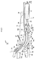
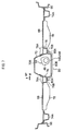
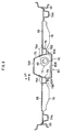
- the exhaust system heat exchanger that carries out heat exchange between an automobile's exhaust gas and a cooling medium, is disposed at the bottom side of a vehicle body floor such that the lowermost portion of the exhaust system heat exchanger is positioned in the vehicle up-down direction above the lowermost portion in the vehicle up-down direction of a vehicle body frame, wherein the vehicle body frame may be configured to include a first member that is positioned in the vehicle up-down direction below one end side in the longitudinal direction of the exhaust system heat exchanger, and a second member that is positioned in the vehicle up-down direction below the other end side in the longitudinal direction of the exhaust system heat exchanger.
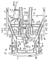
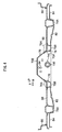
- the exhaust system heat exchanger may be disposed in a floor tunnel provided to the vehicle body floor; and the vehicle body frame may include a pair of tunnel side reinforcements, the longitudinal direction of each of the tunnel side reinforcements being substantially along the vehicle front-rear direction, and the pair of tunnel side reinforcements being provided so as to project from edge portions at both sides in the vehicle width direction of an opening that faces down in the vehicle up-down direction of the floor panel in the vehicle body floor, below the exhaust system heat exchanger in the vehicle up-down direction.
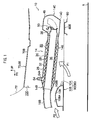
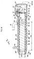
- this exhaust gas introduction portion 26C is connected in a hermetically sealed state to the outer circumferential surface of the upstream end 28A of the inner pipe 28. Furthermore, in the partition wall pipe 26, the portion that protrudes out to the downstream from the outer pipe 32 (from the engine cooling water flow path 34) (a portion to the downstream of the heat exchange portion 14A) is the exhaust gas exhaust portion 26D.
- the exhaust gas exhaust portion 26D is connected in a hermetically sealed state to exhaust gas guide pipe 38 via an end pipe 40.
- the heat exchange portion 14A of the exhaust system heat exchanger 14 is positioned in the vehicle up-down direction so that the lowermost portions 14E are above the bottom faces 76B of the tunnel side reinforcements 76 over their entire lengths in the vehicle front-rear direction. That is to say, it may be understood that the tunnel side reinforcements 76 have bottom faces 76B (lowermost portions) that are positioned in the vehicle up-down direction below the lowermost portion of the lowermost portions 14E (the lowermost portion 14E that is at the rear end of the heat exchange portion 14A), the tunnel side reinforcements 76 corresponding to the vehicle body frame of the present invention.
- the shift cable 94 includes a portion that passes through the top wall 70B of the floor tunnel 70, and leads out to above the exhaust system heat exchanger 14 in the vehicle up-down direction. That is to say, by the shift cable 94 being a portion that has a small amount of radiant heat from the exhaust system in the floor tunnel 70 and being arranged at the top of the exhaust system heat exchanger 14, prevention measures against heat damage may be made simple, and also the lifespan of the shift cable 94 may be increased.
- the valve 54 when the temperature of the engine cooling water is low, then the valve 54 is free of the thermo-actuator 60, and the valve device 50 operates as a self-pressure valve. Due to this, under driving conditions in which the exhaust gas pressure is low, the exhaust gas guide pipe 38, that is to say the bypass flow path 36, is closed by the biasing force of the return spring 56. Therefore, the exhaust gas flows through the exhaust gas flow path 30 of the heat exchange portion 14A, and heat exchange is carried out to the engine cooling water flowing in the engine cooling water flow path 34. Due to this the internal combustion engine warm-up is assisted, and maintenance of heating may be achieved at low temperature on start up.
- the cooling water outlet pipe 64 being in communication with the uppermost portion of the engine cooling water flow path 34, if foreign matter with lower specific gravity than the engine cooling water enters into the engine cooling water flow path 34, even in a state in which the circulation of the engine cooling water is ceased, the foreign matter is ejected from the cooling water outlet pipe 64.
- the outermost layer of the heat exchange portion 14A of the exhaust system heat exchanger 14 is configured as the engine cooling water flow path 34, or in other words, since the engine cooling water is able to carry out heat exchange to the atmosphere through the outer pipe 32 (atmospheric cooling), the generation of bubbles themselves, due to boiling of the engine cooling water, may be suppressed. Furthermore, since the cooling water outlet pipe 64 is simply provided to the outer pipe 32, the structure may be simplified.
Landscapes
- Engineering & Computer Science (AREA)
- Mechanical Engineering (AREA)
- General Engineering & Computer Science (AREA)
- Combustion & Propulsion (AREA)
- Chemical & Material Sciences (AREA)
- Physics & Mathematics (AREA)
- Thermal Sciences (AREA)
- Geometry (AREA)
- Transportation (AREA)
- Cooling, Air Intake And Gas Exhaust, And Fuel Tank Arrangements In Propulsion Units (AREA)
- Body Structure For Vehicles (AREA)
- Exhaust Silencers (AREA)
- Details Of Heat-Exchange And Heat-Transfer (AREA)
Claims (9)
- Fahrzeug, aufweisend einen Fahrzeugkörper (B) und einen Abgassystem-Wärmetauscher (14), der an dem Fahrzeugkörper (B) montiert ist,
wobei der Abgassystem-Wärmetauscher (14) einen Wärmeaustausch zwischen einem Abgas und einem Kühlmedium ausführt und auf einer unteren Seite eines Fahrzeugkörperbodens (70) derart angeordnet ist, dass ein allerunterster Bereich (14D) des Abgassystem-Wärmetauschers (14) in einer von oben nach unten verlaufenden Fahrzeugrichtung über einem alleruntersten Bereich (80B) in der von oben nach unten verlaufenden Fahrzeugrichtung eines Fahrzeugkörperrahmens positioniert ist, wobei der Fahrzeugkörperrahmen aufweist:ein erstes Element (90), das in der von oben nach unten verlaufenden Fahrzeugrichtung unter einer Endseite (14B) in der Längsrichtung des Abgassystem-Wärmetauschers (14) positioniert ist; undein zweites Element (80), das in der von oben nach unten verlaufenden Fahrzeugrichtung unter der anderen Endseite (14C) in der Längsrichtung des Abgassystem-Wärmetauschers (14) positioniert ist. - Fahrzeug nach Anspruch 1, wobei:die Längsrichtung des Abgassystem-Wärmetauschers (14) im Wesentlichen entlang der von vorne nach hinten verlaufenden Fahrzeugrichtung verläuft;das erste Element (90) in der von vorne nach hinten verlaufenden Fahrzeugrichtung des Fahrzeugs vor dem zweiten Element (80) angeordnet ist; undder allerunterste Bereich (80B) des ersten Elements (90) in der von oben nach unten verlaufenden Fahrzeugrichtung in der von oben nach unten verlaufenden Fahrzeugrichtung über dem alleruntersten Bereich (80B) des zweiten Elements (80) in der von oben nach unten verlaufenden Fahrzeugrichtung positioniert ist.
- Fahrzeug nach einem der Ansprüche 1 bis 2, wobei:der Abgassystem-Wärmetauscher (14) in einem Bodentunnel (70) angeordnet ist, der an dem Fahrzeugkörperboden (70) vorgesehen ist; und wobei der Fahrzeugkörperrahmen ferner aufweist:ein Paar von tunnelseitigen Verstärkungen (76), wobei die Längsrichtung einer jeden der tunnelseitigen Verstärkungen (76) im Wesentlichen entlang der von vorne nach hinten verlaufenden Fahrzeugrichtung verläuft, und das Paar von tunnelseitigen Verstärkungen (76) so angeordnet ist, dass es, von Randbereichen an beiden Seiten in der Fahrzeugbreitenrichtung einer Öffnung, die in der von oben nach unten verlaufenden Fahrzeugrichtung des Bodentunnels (70) in dem Fahrzeugkörperboden (70) nach unten gerichtet ist, unter dem Abgassystemwärmetauscher (14) in der von oben nach unten verlaufenden Fahrzeugrichtung vorsteht.
- Fahrzeug nach Anspruch 1, wobei
der allerunterste Bereich (14D) des Abgassystem-Wärmetauschers (14), der den Wärmetausch zwischen dem Abgas und einem Kühlmedium ausführt, das erste Element (90) in der von oben nach unten verlaufenden Fahrzeugrichtung unter der vorderen Endseite in der Längsrichtung des Abgassystem-Wärmetauschers (14) positioniert ist; und
das zweite Element (80) in der von oben nach unten verlaufenden Fahrzeugrichtung unter der hinteren Endseite in der Längsrichtung des Abgassystem-Wärmetauschers (14) positioniert ist. - Fahrzeug nach Anspruch 2 oder 4, wobei:die obere Seite in der von oben nach unten verlaufenden Fahrzeugrichtung des ersten Elements (90) eine geneigt abgewinkelte Fläche (108) aufweist, die derart positioniert ist, dass die Rückseite (108B) der abgewinkelten Fläche (108) in der von vorne nach hinten verlaufenden Fahrzeugrichtung über der Vorderseite (108A) der abgewinkelten Fläche (108) in der von oben nach unten verlaufenden Richtung liegt.
- Fahrzeug nach einem der Ansprüche 1 bis 5, wobei:der Abgassystem-Wärmetauscher (14) derart angeordnet ist, dass die Vorderseite in der von vorne nach hinten verlaufenden Fahrzeugrichtung des Abgassystem-Wärmetauschers (14) in der von oben nach unten verlaufenden Fahrzeugrichtung das Fahrzeugs über der Rückseite des Abgassystem-Wärmetauschers (14) positioniert ist.
- Fahrzeug nach Anspruch 6, wobei der Abgassystem-Wärmetauscher (14) aufweist:einen Strömungsweg (34), der derart angeordnet ist, dass eine Kühlflüssigkeit, bei der es sich um das Kühlmedium handelt, durch denselben hindurchströmt, undein Gasfreisetzungsbereich, von der Oberseite in der von oben nach unten verlaufenden Fahrzeugrichtung, mit dem allerobersten Bereich, in der von oben nach unten verlaufenden Fahrzeugrichtung, des Strömungswegs (34) der Kühlflüssigkeit kommuniziert.
- Fahrzeug nach Anspruch 7, wobei:der Gasfreisetzungsbereich ein Kühlflüssigkeitseinlassbereich (58, 62) und/oder ein Kühlflüssigkeitsauslassbereich (64) des Kühlflüssigkeitsströmungsweges (34) in dem Abgassystem-Wärmetauscher (14) ist.
- Fahrzeug nach eine der Ansprüche 7 oder 8, wobei:eine Hülle (46), die das äußere Profile des Abgassystem-Wärmetauschers (14) bildet, als eine äußere Wand zu dem Kühlflüssigkeits-Strömungsweg (34) konfiguriert ist; undder Gasfreisetzungsbereich an dem allerobersten Bereich in der von oben nach unten verlaufenden Fahrzeugrichtung der Hülle (46) angeordnet ist.
Applications Claiming Priority (1)
| Application Number | Priority Date | Filing Date | Title |
|---|---|---|---|
| JP2006233999A JP4238899B2 (ja) | 2006-08-30 | 2006-08-30 | 排気系熱交換器の車体搭載構造 |
Publications (3)
| Publication Number | Publication Date |
|---|---|
| EP1897741A2 EP1897741A2 (de) | 2008-03-12 |
| EP1897741A3 EP1897741A3 (de) | 2009-11-18 |
| EP1897741B1 true EP1897741B1 (de) | 2012-02-01 |
Family
ID=38704757
Family Applications (1)
| Application Number | Title | Priority Date | Filing Date |
|---|---|---|---|
| EP07016856A Not-in-force EP1897741B1 (de) | 2006-08-30 | 2007-08-28 | Fahrzeug umfassend einen Fahrzeugaufbau und einen Wärmetauscher der Abgasanlage |
Country Status (5)
| Country | Link |
|---|---|
| US (1) | US8225899B2 (de) |
| EP (1) | EP1897741B1 (de) |
| JP (1) | JP4238899B2 (de) |
| KR (1) | KR100888574B1 (de) |
| CN (1) | CN100586750C (de) |
Families Citing this family (22)
| Publication number | Priority date | Publication date | Assignee | Title |
|---|---|---|---|---|
| GB2461854A (en) * | 2008-07-11 | 2010-01-20 | Stephen John Heard | Heat exchange unit for cooling engine exhaust emissions |
| JP5047143B2 (ja) * | 2008-12-18 | 2012-10-10 | 本田技研工業株式会社 | 車両の配線構造 |
| JP5390930B2 (ja) * | 2009-05-12 | 2014-01-15 | 富士重工業株式会社 | 車体前部構造 |
| US8657059B2 (en) * | 2010-03-29 | 2014-02-25 | Ford Global Technologies, Llc | Attachment structure of propeller shaft to cross-member |
| US20120318602A1 (en) * | 2011-06-20 | 2012-12-20 | Caterpillar Inc. | Exhaust System for Machine |
| US8839613B2 (en) * | 2012-02-06 | 2014-09-23 | Ford Global Technologies, Llc | Heat system for an engine |
| JP6074797B2 (ja) * | 2013-01-23 | 2017-02-08 | 本田技研工業株式会社 | 車両における蒸発燃料処理装置 |
| KR101451151B1 (ko) * | 2013-05-27 | 2014-10-15 | 현대자동차주식회사 | 차량용 언더커버 |
| JP6164568B2 (ja) * | 2013-09-30 | 2017-07-19 | スズキ株式会社 | 排気系熱交換器の配置構造 |
| CN103950376B (zh) * | 2014-02-25 | 2016-08-17 | 王树卿 | 汽车增温式节能减排装置 |
| US10156171B2 (en) | 2015-08-07 | 2018-12-18 | Cummins Emission Solutions Inc. | Mounting aftertreatment systems from service joints |
| JP6365500B2 (ja) * | 2015-10-20 | 2018-08-01 | トヨタ自動車株式会社 | 車両床下構造 |
| CN106677869B (zh) * | 2015-11-11 | 2020-11-10 | 福特环球技术公司 | 用于车辆的热回收装置及其总成 |
| JP6610576B2 (ja) * | 2017-02-07 | 2019-11-27 | トヨタ自動車株式会社 | 車両骨格構造 |
| JP6805987B2 (ja) * | 2017-07-10 | 2020-12-23 | トヨタ自動車株式会社 | 排熱回収構造 |
| JP6815947B2 (ja) * | 2017-07-25 | 2021-01-20 | トヨタ自動車株式会社 | 排熱回収構造 |
| JP6897541B2 (ja) * | 2017-12-15 | 2021-06-30 | トヨタ自動車株式会社 | フードロックケーブル配索構造を有する車両前部構造 |
| KR102660369B1 (ko) * | 2019-04-11 | 2024-04-23 | 현대자동차주식회사 | 차량의 전방 차체 |
| CN112519525B (zh) * | 2019-09-17 | 2022-07-22 | 帝亚一维新能源汽车有限公司 | 新能源车辆空调结构和新能源车辆 |
| JP7238812B2 (ja) * | 2020-01-22 | 2023-03-14 | トヨタ自動車株式会社 | 車両用冷却構造 |
| US12103378B2 (en) * | 2021-05-10 | 2024-10-01 | Austin Engineering Usa Services, Inc. | Dual heat path body |
| JP7567844B2 (ja) * | 2022-03-22 | 2024-10-16 | トヨタ自動車株式会社 | 車両前部構造 |
Family Cites Families (18)
| Publication number | Priority date | Publication date | Assignee | Title |
|---|---|---|---|---|
| JPS57150215U (de) | 1981-03-16 | 1982-09-21 | ||
| JPS58211976A (ja) | 1982-06-02 | 1983-12-09 | Nissan Motor Co Ltd | 自動車のフロア下面構造 |
| JPS63100624A (ja) | 1986-11-28 | 1988-05-02 | Matsushita Electric Ind Co Ltd | 光学的再生装置 |
| JPH0259080U (de) | 1988-10-24 | 1990-04-27 | ||
| US5195607A (en) * | 1989-11-21 | 1993-03-23 | Mazda Motor Corporation | Exhaust system for automotive engine |
| JPH1183304A (ja) | 1997-09-10 | 1999-03-26 | Sanyo Electric Co Ltd | 冷却貯蔵庫 |
| KR100302008B1 (ko) | 1999-06-30 | 2001-09-22 | 이계안 | 차량의 냉,난방 시스템 |
| JP4340937B2 (ja) | 1999-09-08 | 2009-10-07 | 株式会社ティラド | クロスフロー型ラジエータ |
| JP2001294029A (ja) | 2000-04-14 | 2001-10-23 | Denso Corp | 熱交換器 |
| JP4032657B2 (ja) * | 2001-03-22 | 2008-01-16 | 三菱自動車工業株式会社 | 車体構造 |
| JP2004025980A (ja) | 2002-06-25 | 2004-01-29 | Toyota Motor Corp | 車両の車体構造 |
| JP2004132320A (ja) * | 2002-10-11 | 2004-04-30 | Toyota Motor Corp | 排気管構造 |
| JP3788780B2 (ja) | 2002-11-19 | 2006-06-21 | 本田技研工業株式会社 | 車両用キャニスタの配置構造 |
| JP2004306809A (ja) | 2003-04-08 | 2004-11-04 | Toyota Motor Corp | 車体後部構造 |
| JP3976199B2 (ja) | 2003-10-16 | 2007-09-12 | 本田技研工業株式会社 | 車体構造 |
| JP4207790B2 (ja) * | 2004-02-02 | 2009-01-14 | トヨタ自動車株式会社 | 車体下部構造 |
| JP2006105464A (ja) | 2004-10-04 | 2006-04-20 | Toyota Motor Corp | 熱交換器及び熱交換装置 |
| JP4542915B2 (ja) | 2005-02-09 | 2010-09-15 | フタバ産業株式会社 | 排気熱回収装置 |
-
2006
- 2006-08-30 JP JP2006233999A patent/JP4238899B2/ja not_active Expired - Fee Related
-
2007
- 2007-08-23 US US11/892,536 patent/US8225899B2/en not_active Expired - Fee Related
- 2007-08-28 EP EP07016856A patent/EP1897741B1/de not_active Not-in-force
- 2007-08-28 CN CN200710145814A patent/CN100586750C/zh not_active Expired - Fee Related
- 2007-08-30 KR KR1020070087782A patent/KR100888574B1/ko not_active Expired - Fee Related
Also Published As
| Publication number | Publication date |
|---|---|
| JP2008057393A (ja) | 2008-03-13 |
| CN100586750C (zh) | 2010-02-03 |
| CN101134433A (zh) | 2008-03-05 |
| US20080066886A1 (en) | 2008-03-20 |
| KR100888574B1 (ko) | 2009-03-12 |
| EP1897741A3 (de) | 2009-11-18 |
| JP4238899B2 (ja) | 2009-03-18 |
| KR20080021549A (ko) | 2008-03-07 |
| US8225899B2 (en) | 2012-07-24 |
| EP1897741A2 (de) | 2008-03-12 |
Similar Documents
| Publication | Publication Date | Title |
|---|---|---|
| EP1897741B1 (de) | Fahrzeug umfassend einen Fahrzeugaufbau und einen Wärmetauscher der Abgasanlage | |
| JP4363448B2 (ja) | 排気系熱交換器の車体搭載構造 | |
| CN101117090B (zh) | 排气系统热交换器的支撑结构 | |
| US10605146B2 (en) | Exhaust mechanism for vehicle | |
| US8056671B2 (en) | Exhaust-gas purification device disposition structure of vehicle | |
| KR20080065555A (ko) | 차량용 배기 시스템 구조 | |
| JP4648790B2 (ja) | 小型車両の排気装置 | |
| US20180119594A1 (en) | Exhaust Pipe Structure | |
| JP2009074552A (ja) | 排気系熱交換器の車体搭載構造 | |
| ES2334271T3 (es) | Un aparato de purificar gases de escape para una motocicleta y motocicleta incluyendo dicho aparato de purificacion de gases de escape. | |
| JP4656014B2 (ja) | 排気系構造 | |
| JP4853632B2 (ja) | エンジンの吸気ダクト構造 | |
| EP2436582B1 (de) | Grätschsitzfahrzeug | |
| EP3428417B1 (de) | Abwärmerückgewinnungsstruktur | |
| JP2009241793A (ja) | 車体前部構造 | |
| JP2009220770A (ja) | 車体前部構造 | |
| JP2020111188A (ja) | 車両の排気構造 | |
| JP2008095527A (ja) | 内燃機関の排気装置 | |
| JP7147182B2 (ja) | 車両 | |
| JP2009220769A (ja) | 車体前部構造 | |
| WO2018078955A1 (ja) | 排気管 | |
| JP2005028921A (ja) | 鞍乗型車両のラジエーター冷却装置 | |
| JP2007118653A (ja) | 鞍乗型車両のエンジン冷却構造 | |
| JP2006258073A (ja) | 内燃機関の排気浄化装置 | |
| JP2020051408A (ja) | 排気構造及び車両 |
Legal Events
| Date | Code | Title | Description |
|---|---|---|---|
| PUAI | Public reference made under article 153(3) epc to a published international application that has entered the european phase |
Free format text: ORIGINAL CODE: 0009012 |
|
| 17P | Request for examination filed |
Effective date: 20070828 |
|
| AK | Designated contracting states |
Kind code of ref document: A2 Designated state(s): AT BE BG CH CY CZ DE DK EE ES FI FR GB GR HU IE IS IT LI LT LU LV MC MT NL PL PT RO SE SI SK TR |
|
| AX | Request for extension of the european patent |
Extension state: AL BA HR MK YU |
|
| PUAL | Search report despatched |
Free format text: ORIGINAL CODE: 0009013 |
|
| AK | Designated contracting states |
Kind code of ref document: A3 Designated state(s): AT BE BG CH CY CZ DE DK EE ES FI FR GB GR HU IE IS IT LI LT LU LV MC MT NL PL PT RO SE SI SK TR |
|
| AX | Request for extension of the european patent |
Extension state: AL BA HR MK RS |
|
| AKX | Designation fees paid |
Designated state(s): DE FR IT |
|
| 17Q | First examination report despatched |
Effective date: 20110325 |
|
| GRAP | Despatch of communication of intention to grant a patent |
Free format text: ORIGINAL CODE: EPIDOSNIGR1 |
|
| RTI1 | Title (correction) |
Free format text: VEHICLE COMPRISING A VEHICLE BODY AND AN EXHAUST SYSTEM HEAT EXCHANGER |
|
| GRAS | Grant fee paid |
Free format text: ORIGINAL CODE: EPIDOSNIGR3 |
|
| GRAA | (expected) grant |
Free format text: ORIGINAL CODE: 0009210 |
|
| RIN1 | Information on inventor provided before grant (corrected) |
Inventor name: MABUCHI, TOMOKI Inventor name: NISHINO, HISASHI |
|
| AK | Designated contracting states |
Kind code of ref document: B1 Designated state(s): DE FR IT |
|
| REG | Reference to a national code |
Ref country code: DE Ref legal event code: R096 Ref document number: 602007020370 Country of ref document: DE Effective date: 20120329 |
|
| PLBE | No opposition filed within time limit |
Free format text: ORIGINAL CODE: 0009261 |
|
| STAA | Information on the status of an ep patent application or granted ep patent |
Free format text: STATUS: NO OPPOSITION FILED WITHIN TIME LIMIT |
|
| 26N | No opposition filed |
Effective date: 20121105 |
|
| REG | Reference to a national code |
Ref country code: DE Ref legal event code: R097 Ref document number: 602007020370 Country of ref document: DE Effective date: 20121105 |
|
| REG | Reference to a national code |
Ref country code: DE Ref legal event code: R084 Ref document number: 602007020370 Country of ref document: DE Effective date: 20130522 |
|
| PGFP | Annual fee paid to national office [announced via postgrant information from national office to epo] |
Ref country code: DE Payment date: 20130821 Year of fee payment: 7 |
|
| PGFP | Annual fee paid to national office [announced via postgrant information from national office to epo] |
Ref country code: FR Payment date: 20130808 Year of fee payment: 7 |
|
| PGFP | Annual fee paid to national office [announced via postgrant information from national office to epo] |
Ref country code: IT Payment date: 20130819 Year of fee payment: 7 |
|
| REG | Reference to a national code |
Ref country code: DE Ref legal event code: R119 Ref document number: 602007020370 Country of ref document: DE |
|
| PG25 | Lapsed in a contracting state [announced via postgrant information from national office to epo] |
Ref country code: IT Free format text: LAPSE BECAUSE OF NON-PAYMENT OF DUE FEES Effective date: 20140828 |
|
| REG | Reference to a national code |
Ref country code: DE Ref legal event code: R119 Ref document number: 602007020370 Country of ref document: DE Effective date: 20150303 |
|
| REG | Reference to a national code |
Ref country code: FR Ref legal event code: ST Effective date: 20150430 |
|
| PG25 | Lapsed in a contracting state [announced via postgrant information from national office to epo] |
Ref country code: DE Free format text: LAPSE BECAUSE OF NON-PAYMENT OF DUE FEES Effective date: 20150303 |
|
| PG25 | Lapsed in a contracting state [announced via postgrant information from national office to epo] |
Ref country code: FR Free format text: LAPSE BECAUSE OF NON-PAYMENT OF DUE FEES Effective date: 20140901 |