EP1897761A2 - Véhicule automobile doté d'un dispositif d'arceau de capote - Google Patents
Véhicule automobile doté d'un dispositif d'arceau de capote Download PDFInfo
- Publication number
- EP1897761A2 EP1897761A2 EP07015435A EP07015435A EP1897761A2 EP 1897761 A2 EP1897761 A2 EP 1897761A2 EP 07015435 A EP07015435 A EP 07015435A EP 07015435 A EP07015435 A EP 07015435A EP 1897761 A2 EP1897761 A2 EP 1897761A2
- Authority
- EP
- European Patent Office
- Prior art keywords
- connecting element
- roll bar
- motor vehicle
- vehicle
- vehicle according
- Prior art date
- Legal status (The legal status is an assumption and is not a legal conclusion. Google has not performed a legal analysis and makes no representation as to the accuracy of the status listed.)
- Withdrawn
Links
Images

Classifications
-
- B—PERFORMING OPERATIONS; TRANSPORTING
- B60—VEHICLES IN GENERAL
- B60R—VEHICLES, VEHICLE FITTINGS, OR VEHICLE PARTS, NOT OTHERWISE PROVIDED FOR
- B60R21/00—Arrangements or fittings on vehicles for protecting or preventing injuries to occupants or pedestrians in case of accidents or other traffic risks
- B60R21/02—Occupant safety arrangements or fittings, e.g. crash pads
- B60R21/13—Roll-over protection
-
- B—PERFORMING OPERATIONS; TRANSPORTING
- B62—LAND VEHICLES FOR TRAVELLING OTHERWISE THAN ON RAILS
- B62D—MOTOR VEHICLES; TRAILERS
- B62D25/00—Superstructure or monocoque structure sub-units; Parts or details thereof not otherwise provided for
- B62D25/08—Front or rear portions
- B62D25/087—Luggage compartments
Definitions
- the present invention relates to a motor vehicle with a roll bar arrangement, which comprises at least one roll bar, a transverse strut and a connecting element with a receiving opening, in which one end of the roll bar is received. Furthermore, the present invention relates to a connecting element for a roll bar arrangement in the motor vehicle.
- Known roll bar assemblies in motor vehicles usually comprise a substantially horizontal and arranged parallel to the transverse axis of the vehicle transverse strut and two mostly U-shaped roll bar.
- the roll bars are in this case attached to the vehicle center end facing the cross member and connected with its second end, which extends to the vehicle outside, via connecting means with the vehicle body.
- the transverse strut is preferably also fastened by means of this connecting device on the vehicle body.
- the European Patent Application EP 1 547 874 A1 describes a roll bar assembly in which the ends of the roll bars, which face the vehicle exterior, extend well down the plane of the crossbar. These extended ends of the roll bar enforce the crossbar and are bolted to it. At this screw connection are tabs attached, which connect the cross-strut roll bar attachment node with a fastener, which in turn is attached to the side body inner wall. In addition, the downwardly extended ends of the roll bars are bolted to a horizontally extending body wall and also connected in the region between the cross member and the horizontal body wall via a tab to the body outer wall. In this roll bar assembly, the consisting of a forming part fastening element on the body outer wall on an extension, are attached to the bolts and other fasteners for storage of the top.
- the object of the present invention is to provide a motor vehicle with an improved roll bar arrangement, which in particular increases the strength of the vehicle body.
- the connecting elements each comprise one Receiving opening, in which both an end of a roll bar and one end of the cross brace are received.
- the cross strut can be made for example from a conventional tubular semi-finished product, as a formed part or preferably as an extruded profile.
- Advantageous in a common storage of the ends of the crossbar and roll bar is the integration of the two elements in a common power flow, which ensures that forces acting on one of the two elements from the outside, can also be absorbed by the other element, creating a significantly increased vehicle stiffness is achieved.
- the receiving opening in the connecting element is preferably designed to be open towards the top and in the direction of the vehicle center.
- the receiving opening is in each case open in the direction of the male elements, the ends of the roll bar and the cross member.
- the receiving opening is closed.
- introduced forces are absorbed practically within the connecting element.
- no critical forces in the vertical direction from the vehicle floor lead the way, which require a positive connection in this direction.
- Due to the mirror-image arrangement of the roll bar arrangement according to the invention the forces which act horizontally along the vehicle transverse axis in the direction of the vehicle center are introduced on the opposite side of the vehicle into the vehicle body.
- the one end of the roll bar and the cross bar are preferably designed so that they are received by the receiving opening of the connecting element substantially positive fit and advantageously as a unit.
- Such a design simplifies the installation of the roll bar arrangement in the motor vehicle and enables a force flow-oriented initiation of occurring forces via contact surfaces in the connecting element.
- detachable fasteners This facilitates assembly and in particular allows easier subsequent replacement of damaged components.
- non-detachable fasteners can be provided. These advantageously reduce the number of assembly steps and the components required in this case, reduce the weight of the assembly and increase the strength of the connection.
- the ends of the roll bars which are preferably tubular, serve as deformation elements which absorb, for example, transverse forces occurring in a side impact. Due to the additional enclosure of the ends of the roll bar through the receiving opening, which additionally acts stiffening, a further destruction of energy is possible. Due to the closed design of the receiving opening in the direction of the vehicle longitudinal axis, relatively high forces, which are introduced obliquely to or in the direction of the vehicle longitudinal axis, can be absorbed by the connecting element.
- the connecting element is supported in a further preferred embodiment of an outer and an inner body wall of the vehicle.
- the inner body wall according to the present body structure, be arranged substantially vertically and / or substantially horizontally.
- it may be the roof of an engine compartment.
- connection of the connecting element on both the outer and on an inner body wall a particularly rigid and solid connection is achieved in the introduced into the connecting element forces, in particular vertical forces, can be advantageously introduced into the vehicle body. On the one hand, this can be enhanced by the double connection enlarged connection area.
- the connections to the outer and inner body panels can be oriented differently and thus optimally accommodate differently directed forces. If, for example, the inner body wall is substantially horizontal, the connecting element can be supported in the vertical direction on it, so that the connection with the outer body wall, which is usually substantially vertical, absorbs only low shear forces. Also, a train in the horizontal vehicle longitudinal direction, as occurs for example when opening a hood hinged to the connecting element, is advantageously absorbed via the connection with a substantially horizontal inner body wall and reduces occurring in the outer body wall shear forces.
- connection of the connecting element to these two body walls according to the invention can be carried out in each case both detachable and insoluble.
- fasteners such as screws, rivets, bolts or snap connections are used for releasable connections, for non-detachable connections preferably joining techniques such as welding, soldering, gluing or permanent forming processes.
- the connecting element can be supported on a horizontal body wall, for example in the case of a vehicle rollover. Even on substantially vertical body walls, the connecting element may be supported on protrusions which are preferably integrated in these walls and which improve the force introduction.
- top bearing in the connecting element.
- both the lateral forces introduced into the top bearing can be taken up as well as the very high tensile forces acting there when opening and closing and forwarded to the vehicle body.
- the connecting element is preferably designed as welded, forged or deformed constructions.
- it is particularly preferred to produce the connecting element as a casting since castings have a very high mechanical strength and thereby provide the design advantages required for such fasteners.
- the integrated into the roll bar assembly connecting elements based on both an inner and on an outer body wall.
- the integrated top storage in the motor vehicle directs the transmitted over the hood on the vehicle forces as well as forces from the Gurtumlenkhebel optimized in the vehicle body and thus increases the safety of the vehicle occupants.
- a vehicle roof is, apart from the locking on the windshield, only connected to the top storage firmly connected to the vehicle. Therefore, it is particularly advantageous lateral forces, which act on the hood, which can be relatively high even at low wind speeds, from the soft top bearings in the roll bar assembly.
- the integration of the top storage in the roll bar assembly of the motor vehicle according to the invention enables a simplified assembly of the top storage and the top of the top storage.
- this particularly preferred embodiment is characterized by a significant improvement in the ease of assembly of all components of the roll bar assembly. This applies both with regard to the inclusion of the ends of roll bar and cross member in the connecting element, as well as with respect to the force-transmitting attachment of the connecting element to the vehicle body, which preferably takes place at least partially form-fitting, especially in the area of inner body panels.
- the resulting elimination of additional required fasteners proves advantageous for the vehicle weight and also for the cost of installation of the vehicle. This not only eliminates the cost of the fasteners but the cost of installing this in the vehicle.
- Particularly advantageous is the flow of force within the roll bar assembly according to the particularly preferred embodiment and the transmission of introduced forces in the vehicle body.
- the reduced space requirement of the roll bar arrangement in the vehicle due to the simple and effective design.
- the optimized power flow between the elements of the roll bar arrangement should be emphasized.
- the resilience of the vehicle safety, in particular the rollover safety, as well as the vehicle stiffness, in particular the transverse stiffness, essential roll bar or crossbar connection significantly improved.
- the roll bar assembly of the motor vehicle according to the invention further avoids any interruption of the power flow or strength-reducing Force curves, which reduces the absorption capacity introduced forces in known systems due to a separate storage of the crossbar and the roll bar.
- Another advantage of the vehicle according to the invention is the integration of the roll bar arrangement, which is arranged directly behind the backrests of the vehicle occupants, as an additional transverse reinforcement in the safety concept of open vehicles. Due to the lack of B-pillar of these vehicles, these have in the area behind the vehicle doors on a reduced transverse stiffness, which is significantly improved by the use of the roll bar assembly.
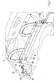
- Fig. 1 shows a three-dimensional view of the roll bar assembly 10 according to the invention, which is shown installed in a motor vehicle.
- the roll bar assembly 10 includes two U-shaped roll bar 11, a cross member 12 and a Connecting element 20 with a receiving opening 21.
- This receiving opening 21 one end of a roll bar 11 and one end of the transverse strut 12 is received in each case.
- the connecting elements 20, which are arranged on both sides between the transverse strut and the inner wall of the body, are executed in mirror image.
- the connecting element 20 is attached to the outer body wall 23.
- the connecting element 20 is on the one hand form-fitting, but additionally fastened by means of a screw 28 on the outer body wall.
- the connecting element 20 is supported horizontally over the contact surface 25 and additionally vertically over the contact surface 26 from. In the embodiment shown, no further fastening elements are attached to the contact surfaces 25 and 26.
- the ends of the roll bars 11, which face the vehicle longitudinal center axis, are suitably fixed in or on the transverse strut.
- the ends of the roll bars, which point in the direction of the outer body walls, are received in the receiving opening 21 of the connecting element 20, which is shown in FIG.
- Fig. 3 shows a section through the connecting element 20 along the section line III - III in Fig. 2 through the receiving opening 21 and the ends located therein of the roll bar 11 and the cross member 12.
- the cross member 12 can be in this exemplary arrangement at a load in the longitudinal direction (transverse to the vehicle longitudinal axis) over the end of the roll bar 11 in the connecting element and thus on the outer body walls 23 are supported.
- the transverse stability of the tubular end of the roll bar 11, which is additionally embraced by the receiving opening is used.
- these are directly or partially over transferred the end of the roll bar 11 in the connecting element and thus to the vehicle body.
- Very high introduced forces lead to the deformation of the cross section of the roll bar 11, wherein the receiving opening 21 of the connecting element 20 also undergoes a deformation.
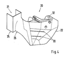
- Fig. 4 shows the connecting element 20 seen from the rear of the vehicle in the direction of the vehicle front.
- integrated in the connecting element hood 30 can be seen, on which the hood is hinged.
- Transverse forces introduced into the convertible top and, in particular, the tensile forces occurring when opening and closing the moving vehicle are picked up by the top bearing 30 and introduced into the vehicle body via the connecting element 20 and via its contact surfaces 22, 25 and 26.
- a Gurtumlenkhebel 32 which also initiates high forces in the vehicle body in the event of an impact, shown.
Landscapes
- Engineering & Computer Science (AREA)
- Mechanical Engineering (AREA)
- Chemical & Material Sciences (AREA)
- Combustion & Propulsion (AREA)
- Transportation (AREA)
- Body Structure For Vehicles (AREA)
- Vehicle Cleaning, Maintenance, Repair, Refitting, And Outriggers (AREA)
Applications Claiming Priority (1)
| Application Number | Priority Date | Filing Date | Title |
|---|---|---|---|
| DE102006042284A DE102006042284A1 (de) | 2006-09-08 | 2006-09-08 | Kraftfahrzeug mit einer Überrollbügelanordnung |
Publications (2)
| Publication Number | Publication Date |
|---|---|
| EP1897761A2 true EP1897761A2 (fr) | 2008-03-12 |
| EP1897761A3 EP1897761A3 (fr) | 2010-06-02 |
Family
ID=38823650
Family Applications (1)
| Application Number | Title | Priority Date | Filing Date |
|---|---|---|---|
| EP07015435A Withdrawn EP1897761A3 (fr) | 2006-09-08 | 2007-08-07 | Véhicule automobile doté d'un dispositif d'arceau de capote |
Country Status (5)
| Country | Link |
|---|---|
| US (1) | US20080061542A1 (fr) |
| EP (1) | EP1897761A3 (fr) |
| JP (1) | JP5306618B2 (fr) |
| CN (1) | CN101138972A (fr) |
| DE (1) | DE102006042284A1 (fr) |
Families Citing this family (12)
| Publication number | Priority date | Publication date | Assignee | Title |
|---|---|---|---|---|
| DE102008049985A1 (de) * | 2008-10-01 | 2010-04-08 | Dr. Ing. H.C. F. Porsche Aktiengesellschaft | Fahrzeugtragstruktur für ein Kraftfahrzeug |
| DE102008050129B4 (de) * | 2008-10-04 | 2026-01-08 | Dr. Ing. H.C. F. Porsche Aktiengesellschaft | Fahrzeugaufbau eines Cabriolet-Fahrzeugs |
| DE202010004753U1 (de) * | 2010-04-09 | 2010-07-22 | Bomag Gmbh | Schwenkbarer Überrollbügel |
| DE102012104812B4 (de) * | 2012-06-04 | 2023-12-07 | Dr. Ing. H.C. F. Porsche Aktiengesellschaft | Kraftfahrzeug mit einem feststehenden Überrollbügel |
| DE102012106974B4 (de) * | 2012-07-31 | 2024-04-11 | Dr. Ing. H.C. F. Porsche Aktiengesellschaft | Dachanordnung und Verfahren zur Montage einer Dachanordnung für ein Cabriolet-Fahrzeug |
| JP6152789B2 (ja) * | 2013-12-05 | 2017-06-28 | マツダ株式会社 | 車両のシートバックバー構造 |
| JP2015182683A (ja) * | 2014-03-25 | 2015-10-22 | ヤマハ発動機株式会社 | 車両 |
| JP5986609B2 (ja) * | 2014-09-17 | 2016-09-06 | 本田技研工業株式会社 | 車体側部構造 |
| DE102015105091A1 (de) * | 2015-04-01 | 2016-10-06 | Dr. Ing. H.C. F. Porsche Aktiengesellschaft | Überrollschutzsystem für ein Kraftfahrzeug |
| CN107150633B (zh) * | 2016-03-04 | 2022-04-01 | 福特环球技术公司 | 车辆中的货物帘端盖组件 |
| US10906590B2 (en) | 2018-12-27 | 2021-02-02 | Honda Motor Co., Ltd. | Vehicle assembly and methods of making and using the same |
| US11345406B2 (en) * | 2019-12-05 | 2022-05-31 | Honda Motor Co., Ltd. | Vehicle assembly with grab bar and methods of making and using the same |
Family Cites Families (14)
| Publication number | Priority date | Publication date | Assignee | Title |
|---|---|---|---|---|
| DE4412108C1 (de) * | 1994-04-08 | 1995-11-02 | Porsche Ag | Überrollbügel für ein Kraftfahrzeug |
| DE19734963A1 (de) * | 1997-08-13 | 1999-02-18 | Bayerische Motoren Werke Ag | Überrollschutzeinrichtung für ein Fahrzeug |
| JP3578441B2 (ja) * | 1998-05-15 | 2004-10-20 | 本田技研工業株式会社 | カブリオレ車における車体補強構造 |
| DE19910007C1 (de) * | 1999-03-08 | 2000-03-30 | Audi Ag | Überrollbügelanordnung an einem Kraftfahrzeug, insbesondere an einem Cabriolet |
| JP2000255356A (ja) * | 1999-03-10 | 2000-09-19 | Toyota Motor Corp | 自動車のロールバーの支持構造 |
| DE20103001U1 (de) * | 2001-02-20 | 2001-06-21 | Blechformwerke Bernsbach GmbH, 08315 Bernsbach | Fahrzeugkörper für ein Pkw-Cabriolet und Baueinheit |
| US7032927B1 (en) * | 2002-09-30 | 2006-04-25 | Joranlien Ric S | Rollbar apparatus for automobiles |
| US7325832B2 (en) * | 2003-12-24 | 2008-02-05 | Mazda Motor Corporation | Roll bar structure of vehicle |
| JP4296942B2 (ja) * | 2004-01-15 | 2009-07-15 | マツダ株式会社 | 車両用シートベルトの取付構造 |
| EP1716020B1 (fr) * | 2004-02-18 | 2008-12-24 | Bayerische Motorenwerke Aktiengesellschaft | Carrosserie de vehicule |
| JP4446775B2 (ja) * | 2004-03-29 | 2010-04-07 | ダイキョーニシカワ株式会社 | ロールバー組立体及びその組付方法 |
| JP4399791B2 (ja) * | 2004-07-02 | 2010-01-20 | マツダ株式会社 | 車両用ロールバーの取り付け構造 |
| JP4507871B2 (ja) * | 2004-12-09 | 2010-07-21 | マツダ株式会社 | オープンカーの後部車体構造 |
| DE102005028929B4 (de) * | 2005-06-22 | 2009-04-09 | Wilhelm Karmann Gmbh | Bauteilgruppe für ein Cabriolet-Kraftfahrzeug |
-
2006
- 2006-09-08 DE DE102006042284A patent/DE102006042284A1/de not_active Withdrawn
-
2007
- 2007-08-07 EP EP07015435A patent/EP1897761A3/fr not_active Withdrawn
- 2007-09-06 JP JP2007230981A patent/JP5306618B2/ja not_active Expired - Fee Related
- 2007-09-07 CN CNA2007101490436A patent/CN101138972A/zh active Pending
- 2007-09-10 US US11/852,537 patent/US20080061542A1/en not_active Abandoned
Also Published As
| Publication number | Publication date |
|---|---|
| EP1897761A3 (fr) | 2010-06-02 |
| DE102006042284A1 (de) | 2008-03-27 |
| JP5306618B2 (ja) | 2013-10-02 |
| US20080061542A1 (en) | 2008-03-13 |
| JP2008062928A (ja) | 2008-03-21 |
| CN101138972A (zh) | 2008-03-12 |
Similar Documents
| Publication | Publication Date | Title |
|---|---|---|
| EP1897761A2 (fr) | Véhicule automobile doté d'un dispositif d'arceau de capote | |
| DE102007006722B4 (de) | Träger für eine Karosserie eines Kraftwagens | |
| DE102011051481B4 (de) | Stoßfängeranordnung für ein Kraftfahrzeug | |
| DE102006055730A1 (de) | Federbeinaufnahme | |
| DE102008039972A1 (de) | Frontstruktur eines Kraftfahrzeugs | |
| EP2643181B1 (fr) | Module avant pour véhicule automobile | |
| EP1984205B1 (fr) | Véhicule automobile équipé d'un dispositif de fixation d'un dossier | |
| DE102022113406B3 (de) | Seitenschweller für eine Kraftwagenkarosserie | |
| DE102008049985A1 (de) | Fahrzeugtragstruktur für ein Kraftfahrzeug | |
| DE102021102366A1 (de) | Stoßfängeranordnung für ein Kraftfahrzeug | |
| DE102009004886B4 (de) | Aufbaustruktur | |
| DE19858303B4 (de) | Vorbaustruktur für eine selbsttragende Rohbaukarosserie eines Personenkraftwagens | |
| EP4035950B1 (fr) | Agencement de pare-chocs à profilé creux d'extrémité | |
| WO2008034481A1 (fr) | Dispositif pour un véhicule destiné à la protection des passagers, en cas d'apport d'énergie orienté vers une portière du véhicule suite à une collision | |
| DE102004050435A1 (de) | Stoßfängersystem für Kraftfahrzeug | |
| DE10119131B4 (de) | Fahrzeugtür | |
| DE19910086C2 (de) | Kraftfahrzeug mit Fahrzeugsitz | |
| DE102005050951B4 (de) | Fronttragstruktur für ein Kraftfahrzeug | |
| DE10223674A1 (de) | Stoßfängeranordnung für einen Vorbau eines Kraftfahrzeugs | |
| DE102005018830B3 (de) | Rahmenkonstruktion zur Aufnahme eines schwenkbar gelagerten Fahrerhauses eines Lastkraftwagens | |
| DE102017118812A1 (de) | Verstärktes Viergelenk | |
| DE102008022641B4 (de) | Kraftwagenkarosserie mit einer Säule und einem Dachrahmenelement | |
| DE10026336B4 (de) | Rohbaukarosserie für einen Personenkraftwagen | |
| DE102005031731B4 (de) | Tragstruktur eines Endbereiches einer Fahrzeugkarosserie | |
| DE102011114384A1 (de) | Karosserie für einen Personenkraftwagen |
Legal Events
| Date | Code | Title | Description |
|---|---|---|---|
| PUAI | Public reference made under article 153(3) epc to a published international application that has entered the european phase |
Free format text: ORIGINAL CODE: 0009012 |
|
| AK | Designated contracting states |
Kind code of ref document: A2 Designated state(s): AT BE BG CH CY CZ DE DK EE ES FI FR GB GR HU IE IS IT LI LT LU LV MC MT NL PL PT RO SE SI SK TR |
|
| AX | Request for extension of the european patent |
Extension state: AL BA HR MK YU |
|
| RAP1 | Party data changed (applicant data changed or rights of an application transferred) |
Owner name: DR. ING. H.C. F. PORSCHE AKTIENGESELLSCHAFT |
|
| RAP1 | Party data changed (applicant data changed or rights of an application transferred) |
Owner name: DR. ING. H.C. F. PORSCHE AKTIENGESELLSCHAFT |
|
| RAP1 | Party data changed (applicant data changed or rights of an application transferred) |
Owner name: DR. ING. H.C. F. PORSCHE AG |
|
| PUAL | Search report despatched |
Free format text: ORIGINAL CODE: 0009013 |
|
| AK | Designated contracting states |
Kind code of ref document: A3 Designated state(s): AT BE BG CH CY CZ DE DK EE ES FI FR GB GR HU IE IS IT LI LT LU LV MC MT NL PL PT RO SE SI SK TR |
|
| AX | Request for extension of the european patent |
Extension state: AL BA HR MK RS |
|
| 17P | Request for examination filed |
Effective date: 20101202 |
|
| D17P | Request for examination filed (deleted) | ||
| AKY | No designation fees paid | ||
| STAA | Information on the status of an ep patent application or granted ep patent |
Free format text: STATUS: THE APPLICATION IS DEEMED TO BE WITHDRAWN |
|
| 18D | Application deemed to be withdrawn |
Effective date: 20101202 |
|
| REG | Reference to a national code |
Ref country code: DE Ref legal event code: R108 Effective date: 20110426 |