EP1897783B1 - Disposition de fixation de came dentelée pour colonne de direction réglable - Google Patents
Disposition de fixation de came dentelée pour colonne de direction réglable Download PDFInfo
- Publication number
- EP1897783B1 EP1897783B1 EP07253497A EP07253497A EP1897783B1 EP 1897783 B1 EP1897783 B1 EP 1897783B1 EP 07253497 A EP07253497 A EP 07253497A EP 07253497 A EP07253497 A EP 07253497A EP 1897783 B1 EP1897783 B1 EP 1897783B1
- Authority
- EP
- European Patent Office
- Prior art keywords
- cam
- steering column
- clamping mechanism
- clamping
- mechanism according
- Prior art date
- Legal status (The legal status is an assumption and is not a legal conclusion. Google has not performed a legal analysis and makes no representation as to the accuracy of the status listed.)
- Ceased
Links
Images

Classifications
-
- B—PERFORMING OPERATIONS; TRANSPORTING
- B62—LAND VEHICLES FOR TRAVELLING OTHERWISE THAN ON RAILS
- B62D—MOTOR VEHICLES; TRAILERS
- B62D1/00—Steering controls, i.e. means for initiating a change of direction of the vehicle
- B62D1/02—Steering controls, i.e. means for initiating a change of direction of the vehicle vehicle-mounted
- B62D1/16—Steering columns
- B62D1/18—Steering columns yieldable or adjustable, e.g. tiltable
- B62D1/184—Mechanisms for locking columns at selected positions
Definitions
- This invention relates to a toothed cam clamping device for an adjustable steering column.
- a clamping mechanism for an adjustable steering column for a vehicle comprising an actuator coupled to a clamping device for clamping the steering column in a desired position, the clamping device acting upon a steering column mounting means, thereby to clamp the steering column
- the clamping device includes a cam mechanism to create clamped and unclamped conditions and the cam mechanism includes a toothed drive cam with a camming face which carries a peripheral toothed profile engaging a toothed rack, which together form a rack and pinion mechanism, the drive cam reacting with a driven cam to provide the clamped and unclamped conditions; characterised in that drive of the toothed rack is electrically effected by means of a reversible electric motor and wherein gearing is provided between a master drive spindle of the motor and a slave driven spindle, the slave driven spindle carrying a thread acting as a worm about which is mounted the rack, which has an internal, axial thread engaging with the worm.
- the rack and pinion mechanism may be of a design similar to that shown and described in GB-A-2 327 257 , but is particularised by the drive cam itself incorporating pinion teeth.
- the cam mechanism itself can incorporate features of, for example, the cam and roller arrangement shown and described in EP-A-0 600 700 .
- Rotation of the toothed cam between clamped and unclamped conditions is achieved by causing the pinion to be driven axially of itself in a translatory motion.
- the drive cam and/or its toothed profile need not be completely circular in profile but need only form as much of a segment of a circle as is required to enable the cam face to be brought into and out of camming engagement with a co-operating cam face of a driven cam of the cam mechanism to provide the clamping and unclamping conditions of the steering column.
- the toothed profile of the drive cam can be formed directly on the periphery of the drive cam or can be a toothed segment joined to the drive cam and extending from a lateral face of the drive cam concentrically of the axis of rotation of the drive cam.
- the drive cam and its toothed pinion part may be made of a plastics material or of a metal such as steel, or a metal alloy.
- a further cam face hereinafter called the idler or driven cam, with which the drive cam co-operates to produce the clamping and unclamping forces, may also be made of the same or similar materials.
- the driven cam may be fixed to a component such as a steering column support bracket or actually forms part of it, or may be fixed to or integral with a separate mounting part.
- This part may be an inner side plate of a casing enclosing the actuator mechanism (motor, gearing etc.)
- a clamping bolt passes through the operational axis of the cam mechanism and through slots in at least one leg of a steering column mounting bracket, as well as at least one member forming part of or joined to a steering column support tube in which the steering column rotates for steering purposes, these parts including adjoining areas which form the clamping surfaces of the clamping mechanism.
- the clamping bolt axis is at right angles to the axis of the steering column.
- At least one pack of interleaved lamell ⁇ may be provided, in known manner, with the clamping bolt passing through slots in them, to enhance the clamping effect of the clamping mechanism.
- the cam faces of the driven and idler cams which are at right angles to the clamping bolt, with the idler cam tightened/fixed on the clamping bolt, act to draw the clamping bolt along its axis in one direction or the other or to allow it to relax, so as to provide the clamped/unclamped conditions of the steering column upon rotation of the driven cam.
- the slots are provided in known manner to permit movement between the relatively moving parts that provide the clamping effort between the steering column and its mounting, the slots in the steering column bracket allowing for rake adjustment and the slots associated with the steering column support member allowing for reach adjustment.
- At least one of the camming surfaces may include rollers, as disclosed in EP-A-0 600 700 , or may have simple, raised profiles, which slide into or out of engagement with a profiled cam track of the camming surface of the other cam face in traditional manner, such as the construction shown and described in GB-A-2 375 809 .
- the steering column may be rake and/or reach adjustable.
- cam mechanism The whole construction of the cam mechanism is arranged to be sufficiently compact that it can be incorporated within an existing, known form of casing for an adjustable steering column clamping mechanism, with only minor modification.
- the invention also extends to an adjustable steering column for a vehicle incorporating a clamping mechanism essentially as defined above.
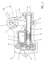
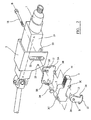
- Figs. 1 and 2 show the general arrangement of a clamping mechanism for an adjustable steering column for a vehicle.
- the general direction of the axis of a steering column 1 is shown by the line A-A, whilst the general axis of the clamping effort of the clamping mechanism is shown by the line B-B.
- the general assembly includes a steering column mounting bracket 2, which in this case incorporates a casing 3 which houses the drive end of a motorised actuator assembly 4 of the clamping mechanism. Visible is an electric motor 5 having a drive spindle 6 on which is mounted a drive gear 7 engaging a driven gear 8 mounted about a slave spindle 9.
- the slave spindle 9 carries a worm 10 which engages with an internal thread of a toothed rack 11 which is mounted for axial reciprocation in slideways 12 within the casing 3.
- the slideways 12 may be formed out of the body of the casing itself.
- the rack 11 engages with teeth 13 of a pinion 14 formed on the external profile of a drive cam 15.
- An inner face of the drive cam 15 is provided with a lifting cam profile 16 which engages with a corresponding driven cam face 17 mounted on a clamping bolt 18 passing through the mounting bracket 2 and flanges of a support bracket 19.
- the clamping bolt 18 acts in known manner upon tightening or loosening of clamping effort through the cam surfaces to provide the clamped/unclamped conditions of the steering column.
- the basic clamping assembly can comprise at least one pack of interleaved lamell ⁇ , not shown, associated with the steering column mounting bracket 2 and steering column support bracket 19, all tightened or loosened by means of the clamping bolt 18, to clamp or un-clamp the steering column 1 in rake and/or reach adjustment mode.
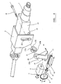
- Figure 3 is a view showing the drive cam 15 carrying the segmental toothed pinion 14 which extends from an outer peripheral portion of the cam 15.
- the shaded area 14A is not required and illustrates how weight and space may be saved within the confines of a vehicle steering column clamping mechanism.
- clamping bolt 18 passes through the apertures 20, 21 shown in the cams 15 and 17, respectively.
- slots 22 are provided in the steering column mounting bracket 2 to allow the steering column 1 to achieve its rake adjustment through the clamping bolt 18, whilst slots 23 are provided in the steering column support bracket 19 to permit reach adjustment of the steering column through the clamping bolt.
- the drive cam 15 is integral with the pinion 14 and engages the driven cam 17, which is formed, by pressing for example, on an inner face of a side plate 3A of the casing 3.
- the inner face of the side plate 3A is provided with securing lugs 3B which mate with corresponding mounting apertures 3C in the main body of the casing 3. This permits easy assembly of the components of the actuator assembly.
- the whole motorised actuator assembly 4 is mounted for pivotal movement remote from the line of one of the rake adjustment slots 22 on and about a pivot pin 24 fitting in an aperture 25 in an outer face of the steering column mounting bracket 2.
- the pivot pin 24 may be fixed to the side plate 3A and allowed to pivot in the aperture 25, or the pivot pin may be free to rotate in both the plate 3A and bracket aperture 25.
- the whole assembly is thus able to move with and therefore accommodate movement of the clamping bolt 18 in the slots 22 in both flanges of the mounting bracket about the pivot pin 24, as indicated by the double arrows at the upper, right-hand side of Fig 1 .
- Fig. 4 shows a possible modification where the driven cam is not integrated with the casing plate 3A but is a separate driven cam component 17A with camming parts 17B.
- the cam component is provided with a slideable block 17C which, when the assembly is mounted, fits in the rake adjustment slot 22 itself for guidance, the clamping bolt 18 passing through an extension of the aperture 21 of the driven cam 17A within the slideable block 17C, with the driven cam restrained by the mounting bracket 2.
- the combined drive cam/pinion arrangement is illustrated with an extended or elongate portion 15A to gain effort through leverage but it will be appreciated that the cam/pinion profile can be basically circular, but with possibly only taking the form of a segment of a circle, such as a quadrant.
Landscapes
- Engineering & Computer Science (AREA)
- Chemical & Material Sciences (AREA)
- Combustion & Propulsion (AREA)
- Transportation (AREA)
- Mechanical Engineering (AREA)
- Steering Controls (AREA)
- Transmission Devices (AREA)
Claims (16)
- Un mécanisme de serrage pour une colonne de direction réglable destinée à un véhicule, comprenant un actionneur (4) couplé à un dispositif de serrage pour serrer la colonne de direction dans une position souhaitée, le dispositif de serrage agissant sur un moyen de montage de colonne de direction, pour serrer de ce fait la colonne de direction, dans lequel le dispositif de serrage comporte un mécanisme à came pour créer des états serrés et non serrés et le mécanisme à came comporte une came d'entraînement dentelée (15) avec une face de came qui porte un profil dentelé périphérique (13) se mettant en prise avec une crémaillère (11) qui, ensemble, forment un mécanisme à pignon et crémaillère, la came d'entraînement réagissant avec une came entraînée (17) pour fournir les états serrés et non serrés ; caractérisé en ce que l'entraînement de la crémaillère (11) est effectué de manière électrique au moyen d'un moteur électrique réversible (5) et dans lequel un engrènement est prévu entre un arbre d'entraînement maître (6) du moteur (5) et un arbre entraîné esclave, l'arbre entraîné esclave (9) portant un filetage qui agit comme une vis sans fin (10) autour de laquelle est montée la crémaillère (11), laquelle présente un filetage axial interne qui se met en prise avec la vis sans fin.
- Un mécanisme de serrage selon la revendication 1, dans lequel la rotation de la came dentelée (15) entre des états serrés et non serrés est obtenue en amenant la crémaillère (11) à être entraînée axialement d'elle-même en un mouvement de translation.
- Un mécanisme de serrage selon l'une quelconque des revendications précédentes, dans lequel la crémaillère (11) est capturée dans au moins une glissière fixe (12) de manière à pouvoir être déplacée axialement d'elle-même afin de faire tourner la came d'entraînement dentelée (15).
- Un mécanisme de serrage selon l'une quelconque des revendications précédentes, dans lequel la came d'entraînement (15) et / ou son profil dentelé (13) est / sont formés en un segment de cercle aussi grand que nécessaire pour permettre à la face de came d'être amenée à entrer en engrènement de came et à en sortir avec la face coopérante d'une pièce entraînée du mécanisme à came afin de fournir les états de serrage et de non serrage de la colonne de direction.
- Un mécanisme de serrage selon l'une quelconque des revendications précédentes, dans lequel le profil dentelé (13) de la came d'entraînement (15) est formé directement sur la périphérie de la came d'entraînement.
- Un mécanisme de serrage selon l'une quelconque des revendications précédentes, dans lequel la came d'entraînement (15) est réalisée en une matière plastique ou en un métal tel que de l'acier, ou un alliage métallique.
- Un mécanisme de serrage selon l'une quelconque des revendications précédentes, dans lequel la came entraînée (17) est réalisée en une matière plastique ou en un métal tel que de l'acier, ou un alliage métallique.
- Un mécanisme de serrage selon la revendication 7, dans lequel la came entraînée (17) est fixée à un composant tel qu'un support de colonne de direction (2), ou est solidaire d'un support de colonne de direction, ou est fixée à ou est solidaire d'une pièce de montage distincte.
- Un mécanisme de serrage selon l'une quelconque des revendications précédentes, dans lequel l'actionneur (4) est monté à l'intérieur d'un carter (13) présentant une plaque de côté interne (3A) pour un montage adjacent à un support de colonne de direction (2), la came entraînée (17) étant montée sur ou solidaire d'un côté interne de ladite plaque de côté interne du carter, de manière à se trouver à l'intérieur du carter lorsque le carter est assemblé.
- Un mécanisme de serrage selon la revendication 7, dans lequel la came entraînée (17) est un composant de came distinct.
- Un mécanisme de serrage selon l'une quelconque des revendications précédentes et comportant un boulon de serrage (18) qui passe à travers un axe opérationnel du mécanisme à came et à travers des fentes (22) dans au moins une patte d'un support de montage de colonne de direction (2) et au moins un élément (19) joint à un tube de support de colonne de direction dans lequel la colonne de direction (1) tourne à des fins de direction lors de l'utilisation, ces pièces comportant après assemblage des zones contiguës qui forment les surfaces de serrage du mécanisme de serrage, l'axe du boulon de serrage étant à angles droits, après assemblage, par rapport à l'axe de la colonne de direction.
- Un mécanisme de serrage selon l'une quelconque des revendications précédentes, dans lequel la came d'entraînement à pignon présente une portion allongée (15A) entre l'axe de rotation de la came et les dents de pignon afin de gagner en effort via une force de levier.
- Un mécanisme de serrage selon l'une quelconque des revendications précédentes, dans lequel la came entraînée (17A) est pourvue d'un bloc (17C) pouvant glisser grâce auquel la came entraînée est montée, lorsque le mécanisme de serrage est assemblé, pour se déplacer de manière à pouvoir glisser dans une fente d'inclinaison réglable du mécanisme de serrage.
- Un mécanisme de serrage selon l'une quelconque des revendications précédentes, dans lequel l'assemblage d'actionneur comportant le mécanisme à came est monté pour se déplacer par pivotement, de manière à pouvoir pivoter lors du réglage de l'inclinaison de la colonne de direction.
- Une colonne de direction destinée à un véhicule incorporant un mécanisme de serrage selon l'une quelconque des revendications précédentes.
- Une colonne de direction selon la revendication 15, dans laquelle le mécanisme de serrage permet un réglage en inclinaison et en hauteur de la colonne de direction et comporte au moins un paquet de lamelles à fentes pour renforcer l'effet de serrage du mécanisme de serrage.
Applications Claiming Priority (1)
| Application Number | Priority Date | Filing Date | Title |
|---|---|---|---|
| GB0617514A GB2441549B (en) | 2006-09-05 | 2006-09-05 | Toothed cam clamping device for adjustable steering column |
Publications (3)
| Publication Number | Publication Date |
|---|---|
| EP1897783A2 EP1897783A2 (fr) | 2008-03-12 |
| EP1897783A3 EP1897783A3 (fr) | 2009-03-18 |
| EP1897783B1 true EP1897783B1 (fr) | 2010-06-02 |
Family
ID=37232436
Family Applications (1)
| Application Number | Title | Priority Date | Filing Date |
|---|---|---|---|
| EP07253497A Ceased EP1897783B1 (fr) | 2006-09-05 | 2007-09-04 | Disposition de fixation de came dentelée pour colonne de direction réglable |
Country Status (3)
| Country | Link |
|---|---|
| EP (1) | EP1897783B1 (fr) |
| DE (1) | DE602007006873D1 (fr) |
| GB (1) | GB2441549B (fr) |
Families Citing this family (2)
| Publication number | Priority date | Publication date | Assignee | Title |
|---|---|---|---|---|
| WO2011134592A1 (fr) | 2010-04-30 | 2011-11-03 | Thyssenkrupp Presta Aktiengesellschaft | Colonne de direction pour un véhicule à moteur |
| US8763491B2 (en) * | 2011-11-03 | 2014-07-01 | Steering Solutions Ip Holding Corporation | Adjustment assembly having a variable gear ratio |
Family Cites Families (9)
| Publication number | Priority date | Publication date | Assignee | Title |
|---|---|---|---|---|
| FR2687628B1 (fr) * | 1992-02-24 | 1997-06-13 | Ecia Equip Composants Ind Auto | Ensemble de colonne de direction reglable en position pour vehicule automobile. |
| GB2273338A (en) | 1992-12-02 | 1994-06-15 | Torrington Co | Steering column clamping mechanism. |
| US6095012A (en) * | 1996-04-18 | 2000-08-01 | Etablissement Supervis | Steering column for a motor vehicle |
| GB9713356D0 (en) * | 1997-06-24 | 1997-08-27 | Nastech Europ Ltd | Adjustable steering column clamping mechanism |
| GB2375809B (en) | 2001-05-23 | 2005-02-23 | Nsk Steering Sys Europ Ltd | Operating lever |
| DE10152807A1 (de) * | 2001-10-25 | 2003-05-15 | Daimler Chrysler Ag | Klemm-Mechanismus für eine verstellbare Lenksäule |
| US7331608B2 (en) * | 2002-06-27 | 2008-02-19 | Delphi Technologies, Inc. | Electrically actuated steering column mechanism |
| DE10240267C1 (de) * | 2002-08-31 | 2003-11-13 | Daimler Chrysler Ag | Klemmvorrichtung für eine verstellbare Lenksäule |
| US7178422B2 (en) * | 2004-07-02 | 2007-02-20 | Delphi Technologies, Inc. | Electrical tilt and telescope locking mechanism |
-
2006
- 2006-09-05 GB GB0617514A patent/GB2441549B/en not_active Expired - Fee Related
-
2007
- 2007-09-04 DE DE602007006873T patent/DE602007006873D1/de active Active
- 2007-09-04 EP EP07253497A patent/EP1897783B1/fr not_active Ceased
Also Published As
| Publication number | Publication date |
|---|---|
| EP1897783A2 (fr) | 2008-03-12 |
| EP1897783A3 (fr) | 2009-03-18 |
| DE602007006873D1 (de) | 2010-07-15 |
| GB0617514D0 (en) | 2006-10-18 |
| GB2441549A (en) | 2008-03-12 |
| GB2441549B (en) | 2009-05-13 |
Similar Documents
| Publication | Publication Date | Title |
|---|---|---|
| US7051986B1 (en) | Spindle and worm drive for adjusting devices in motor vehicles | |
| EP2085291B1 (fr) | Dispositif de reglage de position d'un volant de direction | |
| US20090218800A1 (en) | Steering column with rake and telescope adjustment | |
| US8011265B2 (en) | Modular power actuator | |
| CN111247048B (zh) | 用于机动车辆的转向柱 | |
| CN101765533B (zh) | 用于汽车可调节转向柱的电动夹紧装置 | |
| EP2113441B1 (fr) | Dispositif de serrage électrique d'une colonne de direction avec déplacement d'un actionneur dans une seule direction | |
| EP2553188B1 (fr) | Ensemble poignée pour porte à double paroi | |
| US20090000424A1 (en) | Spindle or worm drive for adjusting devices in motor vehicles | |
| CN105263784B (zh) | 用于生产转向轴轴承单元的方法 | |
| EP2602170A1 (fr) | Appareil de direction | |
| US20210139067A1 (en) | Adjustment drive for a steering column, drive unit for an adjustment drive, motor-adjustable steering column for a motor vehicle, and method for producing an adjustment drive for a steering column | |
| US20180015942A1 (en) | Fastening device and steering apparatus | |
| JP2016034764A (ja) | 電動式ステアリングコラム装置 | |
| EP1897783A2 (fr) | Disposition de fixation de came dentelée pour colonne de direction réglable | |
| JP4528812B2 (ja) | ウィンドウレギュレータ | |
| US20080149413A1 (en) | Electromechanical Power Assisted Steering System | |
| GB2327257A (en) | Reach- and rake-adjustable steering column clamping mechanism with electric actuator | |
| GB2306629A (en) | Adjustable vehicle steering column assembly | |
| JP2002274397A (ja) | 電動パワーステアリング装置 | |
| JP2009214682A (ja) | 電動パワーステアリング装置およびバックラッシ測定方法 | |
| JP2001200912A (ja) | ウォームギヤ装置 | |
| JP6403334B2 (ja) | ステアリング装置 | |
| KR100873097B1 (ko) | 자동차용 전조등의 각도조정장치 | |
| US8955882B2 (en) | Steering apparatus |
Legal Events
| Date | Code | Title | Description |
|---|---|---|---|
| PUAI | Public reference made under article 153(3) epc to a published international application that has entered the european phase |
Free format text: ORIGINAL CODE: 0009012 |
|
| AK | Designated contracting states |
Kind code of ref document: A2 Designated state(s): AT BE BG CH CY CZ DE DK EE ES FI FR GB GR HU IE IS IT LI LT LU LV MC MT NL PL PT RO SE SI SK TR |
|
| AX | Request for extension of the european patent |
Extension state: AL BA HR MK YU |
|
| PUAL | Search report despatched |
Free format text: ORIGINAL CODE: 0009013 |
|
| AK | Designated contracting states |
Kind code of ref document: A3 Designated state(s): AT BE BG CH CY CZ DE DK EE ES FI FR GB GR HU IE IS IT LI LT LU LV MC MT NL PL PT RO SE SI SK TR |
|
| AX | Request for extension of the european patent |
Extension state: AL BA HR MK RS |
|
| 17P | Request for examination filed |
Effective date: 20090916 |
|
| AKX | Designation fees paid |
Designated state(s): DE |
|
| GRAP | Despatch of communication of intention to grant a patent |
Free format text: ORIGINAL CODE: EPIDOSNIGR1 |
|
| GRAS | Grant fee paid |
Free format text: ORIGINAL CODE: EPIDOSNIGR3 |
|
| GRAA | (expected) grant |
Free format text: ORIGINAL CODE: 0009210 |
|
| AK | Designated contracting states |
Kind code of ref document: B1 Designated state(s): DE |
|
| REF | Corresponds to: |
Ref document number: 602007006873 Country of ref document: DE Date of ref document: 20100715 Kind code of ref document: P |
|
| PLBE | No opposition filed within time limit |
Free format text: ORIGINAL CODE: 0009261 |
|
| STAA | Information on the status of an ep patent application or granted ep patent |
Free format text: STATUS: NO OPPOSITION FILED WITHIN TIME LIMIT |
|
| 26N | No opposition filed |
Effective date: 20110303 |
|
| REG | Reference to a national code |
Ref country code: DE Ref legal event code: R097 Ref document number: 602007006873 Country of ref document: DE Effective date: 20110302 |
|
| PGFP | Annual fee paid to national office [announced via postgrant information from national office to epo] |
Ref country code: DE Payment date: 20200826 Year of fee payment: 14 |
|
| REG | Reference to a national code |
Ref country code: DE Ref legal event code: R119 Ref document number: 602007006873 Country of ref document: DE |
|
| PG25 | Lapsed in a contracting state [announced via postgrant information from national office to epo] |
Ref country code: DE Free format text: LAPSE BECAUSE OF NON-PAYMENT OF DUE FEES Effective date: 20220401 |