EP1897784A2 - Electro-mechanical steering - Google Patents
Electro-mechanical steering Download PDFInfo
- Publication number
- EP1897784A2 EP1897784A2 EP07016700A EP07016700A EP1897784A2 EP 1897784 A2 EP1897784 A2 EP 1897784A2 EP 07016700 A EP07016700 A EP 07016700A EP 07016700 A EP07016700 A EP 07016700A EP 1897784 A2 EP1897784 A2 EP 1897784A2
- Authority
- EP
- European Patent Office
- Prior art keywords
- ball screw
- screw nut
- threaded portion
- steering system
- electromechanical steering
- Prior art date
- Legal status (The legal status is an assumption and is not a legal conclusion. Google has not performed a legal analysis and makes no representation as to the accuracy of the status listed.)
- Withdrawn
Links
- 238000005096 rolling process Methods 0.000 claims abstract description 29
- 230000005540 biological transmission Effects 0.000 claims description 7
- 230000002349 favourable effect Effects 0.000 abstract 1
- 238000010276 construction Methods 0.000 description 2
- 230000002411 adverse Effects 0.000 description 1
- 230000002950 deficient Effects 0.000 description 1
- 238000006073 displacement reaction Methods 0.000 description 1
- 230000000694 effects Effects 0.000 description 1
- 238000005516 engineering process Methods 0.000 description 1
- 230000001771 impaired effect Effects 0.000 description 1
- 238000009434 installation Methods 0.000 description 1
- 238000004519 manufacturing process Methods 0.000 description 1
- 230000002028 premature Effects 0.000 description 1
- 238000000926 separation method Methods 0.000 description 1
Images

Classifications
-
- B—PERFORMING OPERATIONS; TRANSPORTING
- B62—LAND VEHICLES FOR TRAVELLING OTHERWISE THAN ON RAILS
- B62D—MOTOR VEHICLES; TRAILERS
- B62D5/00—Power-assisted or power-driven steering
- B62D5/04—Power-assisted or power-driven steering electrical, e.g. using an electric servo-motor connected to, or forming part of, the steering gear
- B62D5/0442—Conversion of rotational into longitudinal movement
- B62D5/0445—Screw drives
- B62D5/0448—Ball nuts
-
- F—MECHANICAL ENGINEERING; LIGHTING; HEATING; WEAPONS; BLASTING
- F16—ENGINEERING ELEMENTS AND UNITS; GENERAL MEASURES FOR PRODUCING AND MAINTAINING EFFECTIVE FUNCTIONING OF MACHINES OR INSTALLATIONS; THERMAL INSULATION IN GENERAL
- F16C—SHAFTS; FLEXIBLE SHAFTS; ELEMENTS OR CRANKSHAFT MECHANISMS; ROTARY BODIES OTHER THAN GEARING ELEMENTS; BEARINGS
- F16C33/00—Parts of bearings; Special methods for making bearings or parts thereof
- F16C33/30—Parts of ball or roller bearings
- F16C33/58—Raceways; Race rings
Definitions
- the invention relates to an electromechanical steering comprising a rack with a threaded portion, a ball screw nut having on its inner circumference provided with a raceway threaded portion and with this via balls with the threaded portion of the rack is engaged, a steering gear housing and a roller bearing on that the ball screw nut is rotatably mounted stationary in the steering gear housing.
- the electric motor as in the EP 1 237 776 B1 shown, arranged coaxially with the rack, so that it can directly drive the cooperating with the rack via balls ball screw nut.
- the electric motor is arranged next to the rack and its drive torque transmitted to the ball screw nut by means of a transmission.
- An example of such an electromechanical steering can be found in the EP 1 237 777 B1 , The forces occurring in this case on the ball screw nut must be supported in the steering gear housing so that the grooves of the threaded sections are loaded as evenly as possible in order to preclude premature wear. Moreover, the running behavior of the ball screw nut should remain as constant as possible, otherwise noticeable changes in the haptic and acoustic properties of the steering can occur.
- the invention is formally based on an electromechanical steering of the second type, as shown in the EP 1 237 777 B1 is described. Under confined spaces, the design shown there is in need of improvement.
- the invention has the object, while maintaining a good support of the ball screw nut to realize a more compact design.
- the steering system according to the invention comprises a rack with a threaded portion, a ball screw nut having on its inner circumference a threaded portion provided with grooves and with this via balls with the threaded portion of the rack is engaged, a steering gear housing and a roller bearing, via which the ball screw nut stationary rotatable in is mounted on the steering gear housing. It is characterized in particular by the fact that the rolling bearing is arranged on the ball screw nut axially offset next to the supporting threaded portion of the ball screw nut.
- the ball screw nut has, beyond its load-bearing threaded section, an extension section on which the roller bearing is arranged on the outside.
- two separate functional areas are created, namely a first functional area for the bearing of the ball screw nut in the steering gear housing and a second functional area for the load-bearing threaded section.
- the axial displacement of these functional areas offers the advantage of a reduced influence on one another.
- forces occurring on the inner race of the rolling bearing and associated deformations are not passed on directly underlying grooves of the threaded portion and vice versa. This results in a tendency to improved wear behavior.
- an inner race of the rolling bearing is integrally formed on the outer circumference of the ball screw nut.
- the ball screw nut in the region of the supporting threaded portion on its outer circumference on one or more ball return channels. Since this area is not impaired by a roller bearing according to the invention, a little more space can be radially provided for the ball returns, resulting in a uniform speed curve of the balls during the return and thus an improved acoustic behavior.
- the or the ball return channels protrude radially from the otherwise substantially cylindrical outer circumference of the ball screw nut.
- the roller bearing is preferably arranged axially offset next to the ball return channels or channels.
- the rolling elements of the rolling bearing are preferably radially at the height of the ball return channels.
- the bearing of the ball screw nut described above preferably comes with exactly one rolling bearing.
- a belt drive can engage the ball screw nut either directly or by attaching a pulley.
- other transmission stages such. B. a gear transmission possible to transmit the drive power of the electric motor to the ball screw nut.
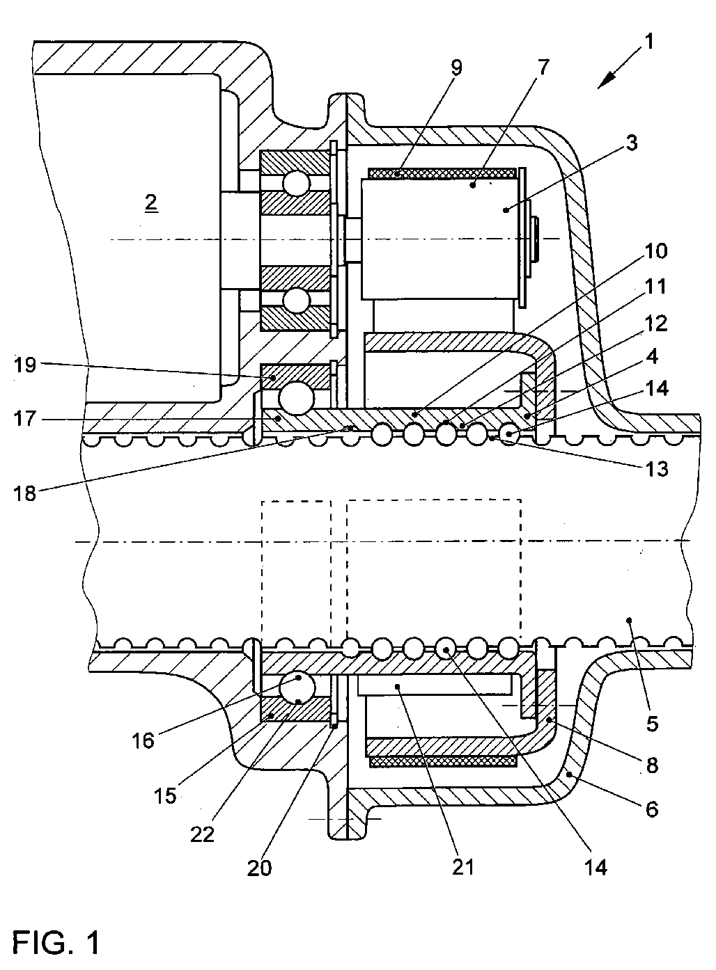
- the exemplary embodiment relates to an electromechanical steering system 1 for a motor vehicle, in which a rotational drive torque of an electric motor 2 is brought into action via a gear stage 3 and a ball screw 4 on a toothed rack 5 coupled to the vehicle wheels as an axial force.
- a split steering housing 6 which has a parting line in the transmission stage 3.
- the gear stage 3 is exemplified here as a belt drive with a drive wheel 7 coupled to the electric motor 2 and a driven wheel 8 coupled to the ball screw drive 4.
- the enveloping this belt is provided with the reference numeral 9.
- the implementation of the rotational movement in a translational movement takes place in the ball screw 4.
- This includes a ball screw nut 10 having a threaded portion 12 provided with grooves 11 on its inner circumference.
- FIG. 1 shows by way of example a single-row deep groove ball bearing 11, but other types of bearing can also be used.
- the inner race 16 of the roller bearing 15 as close as possible to the rack 5 to arrange.
- the rolling bearing 15 is arranged axially offset on the ball screw nut next to the supporting threaded portion 12 of the ball screw nut 10.
- the ball screw nut 10 In order to exclude mutual adverse effects on the running properties of the ball screw 4 and of the roller bearing 15, the ball screw nut 10 has an extension section 17 which projects beyond the supporting threaded section 12. Under the supporting threaded portion 12 of that part of the internal thread on the ball screw nut 10 is understood, which actually comes with balls 14 into engagement. A production-related outlet 18 of the internal thread into the extension section 17 is in on the other hand, in the absence of contact with the balls 14, no longer to be understood as a load-bearing threaded section 12.
- the inner race 16 of the roller bearing 15 is located in a radial area around the extension portion 17. Slight overlaps of the rolling bearing 15 with the supporting threaded portion 12 can be tolerated insofar as the inner race 16 of the rolling bearing 15 completely falls in the region of the extension portion 17.
- the rolling bearing 15 can in principle be designed with its own inner ring and its own outer ring 19. In the illustrated embodiment, however, the inner ring is already integrated into the ball screw nut 10, namely in its extension portion 17. The inner race 16 of the rolling bearing 15 is thus located directly on the outer circumference of the ball screw nut 10th
- the outer ring 19 of the rolling bearing 15, however, can be carried out in a conventional design and arranged and fixed in the steering gear housing 6 in a corresponding receiving recess 20.
- the outer diameter of the rolling bearing 15 can be made relatively small. As a result, as can be seen from FIG. 1, more space is gained for the arrangement and mounting of the electric motor 2 and the gear stage 3 and overall a more radially compact construction is made possible.
- one or more ball return channels 21 may be provided on the outer circumference of the ball screw nut 10 in the region of the supporting threaded portion 12.
- the rolling bearing 15 it is also possible to extend this ball return channels 12 beyond the otherwise substantially cylindrical outer periphery of the ball screw nut 10 addition. This makes it possible to achieve a more uniform speed curve of the balls 14 during the return, which can reduce the noise emissions of the steering.
- the projection of the ball return channels 12 is unproblematic, since they run within the gear stage 3 and the belt drive.
- the ball return channels 12 will preferably be at the height of the rolling elements 22.
Landscapes
- Engineering & Computer Science (AREA)
- Mechanical Engineering (AREA)
- General Engineering & Computer Science (AREA)
- Chemical & Material Sciences (AREA)
- Combustion & Propulsion (AREA)
- Transportation (AREA)
- Power Steering Mechanism (AREA)
- Transmission Devices (AREA)
Abstract
Eine elektromechanische Lenkung umfasst eine Zahnstange (5) mit einem Gewindeabschnitt (13), eine Kugelgewindemutter (10), die an ihrem Innenumfang einen mit Laufrillen (11) versehenen Gewindeabschnitt (12) aufweist und mit diesem über Kugeln (14) mit dem Gewindeabschnitt (13) der Zahnstange (5) in Eingriff steht, ein Lenkgetriebegehäuse (6) und ein Wälzlager (15), über das die Kugelgewindemutter (10) ortsfest drehbar in dem Lenkgetriebegehäuse (6) gelagert ist. Das Wälzlager (15) ist an der Kugelgewindemutter (10) axial versetzt neben dem tragenden Gewindeabschnitt (12) der Kugelgewindemutter (10) angeordnet. Dies ermöglicht eine kompaktere Bauweise und gestattet eine günstige Kugelrückführung.
Description
Die Erfindung bezieht sich auf eine elektromechanische Lenkung, umfassend eine Zahnstange mit einem Gewindeabschnitt, eine Kugelgewindemutter, die an ihrem Innenumfang einen mit Laufrillen versehenen Gewindeabschnitt aufweist und mit diesem über Kugeln mit dem Gewindeabschnitt der Zahnstange in Eingriff steht, ein Lenkgetriebegehäuse und ein Wälzlager, über das die Kugelgewindemutter ortsfest drehbar in dem Lenkgetriebegehäuse gelagert ist.The invention relates to an electromechanical steering comprising a rack with a threaded portion, a ball screw nut having on its inner circumference provided with a raceway threaded portion and with this via balls with the threaded portion of the rack is engaged, a steering gear housing and a roller bearing on that the ball screw nut is rotatably mounted stationary in the steering gear housing.
Im Kraftfahrzeugbau werden herkömmliche, hydraulische Lenkungen zunehmend durch elektromechanische Lenkungen ersetzt, bei denen eine den Fahrer unterstützende Hilfskraft nicht mehr hydraulisch sondern elektrisch mittels eines Elektromotors erzeugt wird.In the automotive industry, conventional, hydraulic steering systems are increasingly being replaced by electromechanical steering systems, in which a driver assisting auxiliary power is no longer generated hydraulically but electrically by means of an electric motor.
Bei einem ersten Typ elektromechanischer Lenkungen wird der Elektromotor, wie in der
Bei einem zweiten Typ elektromechanischer Lenkungen wird der Elektromotor neben der Zahnstange angeordnet und dessen Antriebsmoment auf die Kugelgewindemutter mittels eines Getriebes übertragen. Ein Beispiel für eine solche elektromechanische Lenkung findet sich in der
Die Erfindung geht formal von einer elektromechanischen Lenkung des zweiten Typs aus, wie sie in der
Davon ausgehend liegt der Erfindung die Aufgabe zugrunde, unter Aufrechterhaltung einer guten Abstützung der Kugelgewindemutter eine kompaktere Bauweise zu realisieren.On this basis, the invention has the object, while maintaining a good support of the ball screw nut to realize a more compact design.
Diese Aufgabe wird durch eine elektromechanische Lenkung gemäß Patentanspruch 1 gelöst. Die erfindungsgemäße Lenkung umfasst eine Zahnstange mit einem Gewindeabschnitt, eine Kugelgewindemutter, die an ihrem Innenumfang einen mit Laufrillen versehenen Gewindeabschnitt aufweist und mit diesem über Kugeln mit dem Gewindeabschnitt der Zahnstange in Eingriff steht, ein Lenkgetriebegehäuse und ein Wälzlager, über das die Kugelgewindemutter ortsfest drehbar in dem Lenkgetriebegehäuse gelagert ist. Sie zeichnet sich insbesondere dadurch aus, dass das Wälzlager an der Kugelgewindemutter axial versetzt neben dem tragenden Gewindeabschnitt der Kugelgewindemutter angeordnet ist.This object is achieved by an electromechanical steering system according to
Hierdurch ist es ohne eine Beeinträchtigung des Laufverhaltens der Kugelgewindemutter möglich, das Wälzlager näher an der Achse der Zahnstange anzuordnen, so dass ein Wälzlager mit einem kleineren Außendurchmesser gewählt werden kann. Die hiermit verbundene axiale Verlängerung der Kugelgewindemutter erfolgt in eine verhältnismäßig bauraumunkritische Richtung. Insbesondere bei elektromechanischen Lenkungen, bei denen der Motor nicht koaxial, sondern neben der Zahnstange angeordnet ist, bringt die schlankere Ausgestaltung der Lagerung der Kugelgewindemutter mehr Gestaltungsspielraum in Bezug auf die Anordnung des Elektromotors und einer zwischen diesem und der Kugelgewindemutter vorgesehenen Getriebestufe.This makes it possible without affecting the running behavior of the ball screw nut to arrange the rolling bearing closer to the axis of the rack, so that a rolling bearing can be selected with a smaller outer diameter. The associated axial extension of the ball screw nut takes place in a relatively space-deficient direction. In particular, in electromechanical steering systems, in which the motor is not coaxial, but arranged next to the rack, brings the slimmer design of the ball bearing nut more freedom in terms of the arrangement of the electric motor and provided between this and the ball screw nut gear stage.
Weitere, vorteilhafte Ausgestaltungen der Erfindung sind in den Patentansprüchen angegeben.Further, advantageous embodiments of the invention are specified in the patent claims.
Gemäß einer ersten, vorteilhaften Ausgestaltung ist vorgesehen, dass die Kugelgewindemutter über ihren tragenden Gewindeabschnitt hinaus einen Verlängerungsabschnitt aufweist, an dem außenseitig das Wälzlager angeordnet ist. Hierdurch werden zwei getrennte Funktionsbereiche geschaffen, nämlich ein erster Funktionsbereich für die Lagerung der Kugelgewindemutter im Lenkgetriebegehäuse und ein zweiter Funktionsbereich für den tragenden Gewindeabschnitt. Das axiale versetzen dieser Funktionsbereiche, die in Figur 1 durch unterbrochene Linien angedeutet sind, bietet den Vorteil einer geminderten Beeinflussung untereinander. So werden beispielsweise an der inneren Laufbahn des Wälzlagers auftretende Kräfte und damit verbundene Verformungen nicht an unmittelbar darunterliegende Laufrillen des Gewindeabschnitts weitergegeben und umgekehrt. Hieraus resultiert ein tendenziell verbessertes Verschleißverhalten.According to a first, advantageous embodiment, it is provided that the ball screw nut has, beyond its load-bearing threaded section, an extension section on which the roller bearing is arranged on the outside. As a result, two separate functional areas are created, namely a first functional area for the bearing of the ball screw nut in the steering gear housing and a second functional area for the load-bearing threaded section. The axial displacement of these functional areas, which are indicated by broken lines in FIG. 1, offers the advantage of a reduced influence on one another. Thus, for example, forces occurring on the inner race of the rolling bearing and associated deformations are not passed on directly underlying grooves of the threaded portion and vice versa. This results in a tendency to improved wear behavior.
Gemäß einer weiteren, vorteilhaften Ausgestaltung ist eine innere Laufbahn des Wälzlagers integral am Außenumfang der Kugelgewindemutter ausgebildet. Durch die vorstehend erläuterte Trennung der Funktionsbereiche kann der ansonsten gebräuchliche Innenring eines Wälzlagers vollständig entfallen. Dies führt zu einer weiter verschlankten Bauweise.According to a further advantageous embodiment, an inner race of the rolling bearing is integrally formed on the outer circumference of the ball screw nut. By the above explained separation of the functional areas of the otherwise common inner ring of a rolling bearing can be completely eliminated. This leads to a further streamlined construction.
Vorzugsweise weist die Kugelgewindemutter im Bereich des tragenden Gewindeabschnitts an ihrem Außenumfang einen oder mehrere Kugelrückführkanäle auf. Da dieser Bereich erfindungsgemäß nicht durch ein Wälzlager beeinträchtigt ist, kann für die Kugelrückführungen radial etwas mehr Platz vorgesehen werden, wodurch sich ein gleichmäßiger Geschwindigkeitsverlauf der Kugeln während der Rückführung und somit ein verbessertes Akustikverhalten einstellt.Preferably, the ball screw nut in the region of the supporting threaded portion on its outer circumference on one or more ball return channels. Since this area is not impaired by a roller bearing according to the invention, a little more space can be radially provided for the ball returns, resulting in a uniform speed curve of the balls during the return and thus an improved acoustic behavior.
Dabei kann vorgesehen sein, dass der bzw. die Kugelrückführkanäle radial vom ansonsten im Wesentlichen zylindrischen Außenumfang der Kugelgewindemutter abstehen.It can be provided that the or the ball return channels protrude radially from the otherwise substantially cylindrical outer circumference of the ball screw nut.
Wie bereits erwähnt, wird das Wälzlager bevorzugt axial versetzt neben dem bzw. den Kugelrückführkanälen angeordnet. Mit Blick auf eine kompakte Bauweise liegen die Wälzkörper des Wälzlagers vorzugsweise radial auf der Höhe der Kugelrückführkanäle.As already mentioned, the roller bearing is preferably arranged axially offset next to the ball return channels or channels. With a view to a compact design, the rolling elements of the rolling bearing are preferably radially at the height of the ball return channels.
Die vorstehend beschriebene Lagerung der Kugelgewindemutter kommt vorzugsweise mit genau einen Wälzlager aus.The bearing of the ball screw nut described above preferably comes with exactly one rolling bearing.
Ferner kann an der Kugelgewindemutter entweder unmittelbar oder durch Anbringung eines Riemenrads ein Riementrieb angreifen. Jedoch sind auch andere Getriebestufen, wie z. B. ein Zahnradgetriebe möglich, um die Antriebsleistung des Elektromotors auf die Kugelgewindemutter zu übertragen.Further, a belt drive can engage the ball screw nut either directly or by attaching a pulley. However, other transmission stages, such. B. a gear transmission possible to transmit the drive power of the electric motor to the ball screw nut.
Nachfolgend wird die Erfindung anhand eines in der Zeichnung dargestellten Ausführungsbeispiels näher erläutert. Die Zeichnung zeigt in:
Figur 1- eine Teilsschnittansicht einer elektromechanischen Lenkung nach einem Ausführungsbeispiel der Erfindung.
- FIG. 1
- a partial sectional view of an electromechanical steering according to an embodiment of the invention.
Das Ausführungsbeispiel bezieht sich auf eine elektromechanische Lenkung 1 für ein Kraftfahrzeug, bei der ein rotatorisches Antriebsmoment eines Elektromotor 2 über eine Getriebestufe 3 und einen Kugelgewindetrieb 4 an einer mit den Fahrzeugrädern gekoppelten Zahnstange 5 als Axialkraft zur Wirkung gebracht wird.The exemplary embodiment relates to an
Weiterhin ist ein geteiltes Lenkungsgehäuse 6 zu vorgesehen, das eine Trennfuge im Bereich der Getriebestufe 3 aufweist.Furthermore, a split
Die Getriebestufe 3 ist hier beispielhaft als Riementrieb mit einem mit dem Elektromotor 2 gekoppelten Antriebsrad 7 und einem mit dem Kugelgewindetrieb 4 gekoppelten Abtriebsrad 8 ausgebildet. Der diese einhüllende Riemen ist mit dem Bezugszeichen 9 versehen.The
Anstelle eines Riementriebs kann jedoch auch ein anderes Getriebe, beispielsweise ein Zahnradgetriebe vorgesehen sein.Instead of a belt drive, however, it is also possible to provide another transmission, for example a gear transmission.
Die Umsetzung der Rotationsbewegung in eine Translationsbewegung erfolgt in dem Kugelgewindetrieb 4. Dieser umfasst eine Kugelgewindemutter 10, die an ihrem Innenumfang einen mit Laufrillen 11 versehenen Gewindeabschnitt 12 aufweist.The implementation of the rotational movement in a translational movement takes place in the
An der Zahnstange 5 befindet sich gegenüberliegend ein entsprechender Gewindeabschnitt 13. Beide Gewindeabschnitte stehen über umlaufende Kugeln 14 miteinander in Eingriff.On the
Da die Kugelgewindemutter 10 ortsfest, jedoch drehbar im Lenkgetriebegehäuse 6 gelagert ist, führt eine Drehung der Kugelgewindemutter 10 zu einer Translation der Zahnstange 5.Since the ball screw nut 10 stationary, but is rotatably mounted in the
Bei dem dargestellten Ausführungsbeispiel ist die Kugelgewindemutter 10 über ein einziges - Wälzlager 15, das als Festlager ausgebildet ist, im Lenkgetriebegehäuse 6 abgestützt. Figur 1 zeigt beispielhaft ein einreihiges Rillenkugellager 11, jedoch können auch andere Lagertypen zum Einsatz kommen.In the illustrated embodiment, the
Erfindungsgemäß ist vorgesehen, die innere Laufbahn 16 des Wälzlagers 15 möglichst nahe zur Zahnstange 5 hin anzuordnen. Aus diesem Grunde ist das Wälzlager 15 an der Kugelgewindemutter axial versetzt neben dem tragenden Gewindeabschnitt 12 der Kugelgewindemutter 10 angeordnet.According to the invention, the
Um gegenseitige Beeinträchtigungen der Laufeigenschaften des Kugelgewindetriebs 4 sowie des Wälzlagers 15 auszuschließen, weist die Kugelgewindemutter 10 einen Verlängerungsabschnitt 17 auf, der über den tragenden Gewindeabschnitt 12 hinausragt. Unter dem tragenden Gewindeabschnitt 12 wird derjenige Teil des Innengewindes an der Kugelgewindemutter 10 verstanden, der tatsächlich mit Kugeln 14 in Eingriff gelangt. Ein fertigungsbedingter Auslauf 18 des Innengewindes in den Verlängerungsabschnitt 17 hinein ist hingegen, mangels Kontakt mit den Kugeln 14, nicht mehr als tragender Gewindeabschnitt 12 zu verstehen.In order to exclude mutual adverse effects on the running properties of the
Die innere Laufbahn 16 des Wälzlagers 15 befindet in einem radialen Bereich um den Verlängerungsabschnitt 17. Geringfügige Überlappungen des Wälzlagers 15 mit dem tragenden Gewindeabschnitt 12 können insoweit toleriert werden, als die innere Laufbahn 16 des Wälzlagers 15 vollständig in den Bereich des Verlängerungsabschnitts 17 fällt.The
Das Wälzlager 15 kann prinzipiell mit einem eigenen Innenring und einem eigenen Außenring 19 ausgeführt werden. Bei dem dargestellten Ausführungsbeispiel ist jedoch der Innenring bereits in die Kugelgewindemutter 10, nämlich in deren Verlängerungsabschnitt 17 integriert. Die innere Laufbahn 16 des Wälzlagers 15 befindet sich somit unmittelbar am Außenumfang der Kugelgewindemutter 10.The rolling
Der Außenring 19 des Wälzlagers 15 kann hingegen in herkömmlicher Bauart ausgeführt und im Lenkgetriebegehäuse 6 in einer entsprechenden Aufnahmeausnehmung 20 angeordnet und festgelegt werden.The
Durch die teilweise Einbeziehung des Wälzlagers 15 in die Kugelgewindemutter 10 lässt sich der Außendurchmesser des Wälzlagers 15 verhältnismäßig klein gestalten. Hierdurch wird, wie Figur 1 entnommen werden kann, für die Anordnung und Lagerung des Elektromotors 2 sowie der Getriebestufe 3 mehr Bauraum gewonnen und insgesamt eine radial kompaktere Bauweise ermöglicht.Due to the partial inclusion of the rolling bearing 15 in the
Wie Figur 1 weiter zeigt, können am Außenumfang der Kugelgewindemutter 10 im Bereich des tragenden Gewindeabschnitts 12 ein oder mehrere Kugelrückführkanäle 21 vorgesehen werden. Durch die Anordnung des Wälzlagers 15 neben dem tragenden Gewindeabschnitt 12 ist es überdies möglich, diese Kugelrückführkanäle 12 über den ansonsten im Wesentlichen zylindrischen Außenumfang der Kugelgewindemutter 10 hinaus zu erstrecken. Hierdurch lässt sich ein gleichmäßigerer Geschwindigkeitsverlauf der Kugeln 14 während der Rückführung erzielen, wodurch sich die Geräuschemissionen der Lenkung verringern lassen.As Figure 1 further shows, one or more
Bauraumtechnisch ist das Vorstehen der Kugelrückführkanäle 12 unproblematisch, da diese innerhalb der Getriebestufe 3 bzw. des Riementriebs verlaufen. In der Praxis werden die Kugelrückführkanäle 12 vorzugsweise auf der Höhe der Wälzkörper 22 liegen.Installation space technology, the projection of the
Die Erfindung wurde vorstehend anhand eines bevorzugten Ausführungsbeispiels näher erläutert. Sie ist jedoch nicht auf dieses Ausführungsbeispiel beschränkt, sondern umfasst alle durch die Patentansprüche definierten Ausgestaltungen.The invention has been explained in more detail above with reference to a preferred embodiment. However, it is not limited to this embodiment, but includes all the embodiments defined by the claims.
- 11
- elektromechanische LenkungElectric Power Steering
- 22
- Elektromotorelectric motor
- 33
- Getriebestufegear stage
- 44
- KugelgewindetriebBall Screw
- 55
- Zahnstangerack
- 66
- LenkgetriebegehäuseSteering gear housing
- 77
- Antriebsraddrive wheel
- 88th
- Abtriebsradoutput gear
- 99
- Riemenbelt
- 1010
- KugelgewindemutterBall screw nut
- 1111
- Laufrillenraceways
- 1212
- tragender Gewindeabschnitt der Kugelgewindemutterbearing threaded portion of the ball screw nut
- 1313
- Gewindeabschnitt der ZahnstangeThread section of the rack
- 1414
- KugelBullet
- 1515
- Wälzlagerroller bearing
- 1616
- innere Laufbahn des Wälzlagersinner raceway of the rolling bearing
- 1717
- Verlängerungsabschnittextension section
- 1818
- Auslaufoutlet
- 1919
- Außenring des WälzlagersOuter ring of the rolling bearing
- 2020
- Ausnehmungenrecesses
- 2121
- KugelrückführkanalBall return channel
- 2222
- Wälzkörperrolling elements
Claims (9)
das Wälzlager (15) an der Kugelgewindemutter (10) axial versetzt neben dem tragenden Gewindeabschnitt (12) der Kugelgewindemutter (10) angeordnet ist.Electromechanical steering, comprising:
the rolling bearing (15) on the ball screw nut (10) axially offset adjacent the supporting threaded portion (12) of the ball screw nut (10) is arranged.
Applications Claiming Priority (1)
| Application Number | Priority Date | Filing Date | Title |
|---|---|---|---|
| DE200610041718 DE102006041718A1 (en) | 2006-09-06 | 2006-09-06 | Electric Power Steering |
Publications (2)
| Publication Number | Publication Date |
|---|---|
| EP1897784A2 true EP1897784A2 (en) | 2008-03-12 |
| EP1897784A3 EP1897784A3 (en) | 2008-09-24 |
Family
ID=38779675
Family Applications (1)
| Application Number | Title | Priority Date | Filing Date |
|---|---|---|---|
| EP07016700A Withdrawn EP1897784A3 (en) | 2006-09-06 | 2007-08-25 | Electro-mechanical steering |
Country Status (2)
| Country | Link |
|---|---|
| EP (1) | EP1897784A3 (en) |
| DE (1) | DE102006041718A1 (en) |
Cited By (5)
| Publication number | Priority date | Publication date | Assignee | Title |
|---|---|---|---|---|
| JP2015047997A (en) * | 2013-09-03 | 2015-03-16 | 日立オートモティブシステムズステアリング株式会社 | Power steering device and manufacturing method for power steering device |
| JP2018008693A (en) * | 2017-08-30 | 2018-01-18 | 日立オートモティブシステムズ株式会社 | Power steering device |
| WO2018131358A1 (en) * | 2017-01-11 | 2018-07-19 | 日立オートモティブシステムズ株式会社 | Power steering device |
| WO2018135107A1 (en) * | 2017-01-20 | 2018-07-26 | 日立オートモティブシステムズ株式会社 | Power steering apparatus |
| CN112550440A (en) * | 2019-09-25 | 2021-03-26 | 操纵技术Ip控股公司 | Cam driving pulley for electric power steering system |
Families Citing this family (4)
| Publication number | Priority date | Publication date | Assignee | Title |
|---|---|---|---|---|
| DE102008021895A1 (en) | 2008-05-02 | 2012-12-06 | Volkswagen Aktiengesellschaft | Electromechanical steering for vehicle, has belt wheel with through holes releasing screws in rotational position of belt wheel relative to outer bearing ring, where outer diameter of wheel is greater than screw fastening diameter of ring |
| DE102008026939B4 (en) | 2008-06-05 | 2022-12-08 | Volkswagen Ag | Method for determining a state of fatigue of the bearings of an electromechanical steering system |
| DE102008028055A1 (en) | 2008-06-12 | 2009-12-17 | Volkswagen Ag | Driving power supplying method for electromechanical steering mechanism in vehicle, involves providing motor maximum power threshold value based on temperature of motor and control unit so that value is retracted with increasing temperature |
| DE102010051268B4 (en) | 2010-11-12 | 2024-08-22 | Volkswagen Ag | Ball screw drive of the type without separating spacers between the balls for an electromechanical vehicle steering system |
Citations (2)
| Publication number | Priority date | Publication date | Assignee | Title |
|---|---|---|---|---|
| EP1237777A1 (en) | 1999-12-17 | 2002-09-11 | ZF Lenksysteme GmbH | Steering device for a vehicle |
| EP1237776A1 (en) | 1999-12-01 | 2002-09-11 | Krupp Presta Aktiengesellschaft | High-efficiency tubular electrical steering servo |
Family Cites Families (7)
| Publication number | Priority date | Publication date | Assignee | Title |
|---|---|---|---|---|
| GB2388353B (en) * | 2000-07-21 | 2004-04-21 | Nsk Ltd | Electrically driven power steering apparatus |
| DE10258826A1 (en) * | 2002-12-17 | 2004-07-15 | Ina-Schaeffler Kg | Drive device with a Wälzkörpergewindetrieb |
| KR100565805B1 (en) * | 2003-12-22 | 2006-03-29 | 삼성전자주식회사 | Toner consumption measuring device and method |
| JP2005218980A (en) * | 2004-02-06 | 2005-08-18 | Car Mate Mfg Co Ltd | Coating method of coating composition and coating composition-impregnated body |
| DE102004038951A1 (en) * | 2004-08-11 | 2006-02-23 | Ina-Schaeffler Kg | Ball Screw |
| DE102004039820A1 (en) * | 2004-08-17 | 2006-02-23 | Ina-Schaeffler Kg | Steering support for the steering device of a motor vehicle |
| DE102004058963A1 (en) * | 2004-12-08 | 2006-06-14 | Schaeffler Kg | Timing pulley |
-
2006
- 2006-09-06 DE DE200610041718 patent/DE102006041718A1/en not_active Ceased
-
2007
- 2007-08-25 EP EP07016700A patent/EP1897784A3/en not_active Withdrawn
Patent Citations (2)
| Publication number | Priority date | Publication date | Assignee | Title |
|---|---|---|---|---|
| EP1237776A1 (en) | 1999-12-01 | 2002-09-11 | Krupp Presta Aktiengesellschaft | High-efficiency tubular electrical steering servo |
| EP1237777A1 (en) | 1999-12-17 | 2002-09-11 | ZF Lenksysteme GmbH | Steering device for a vehicle |
Cited By (10)
| Publication number | Priority date | Publication date | Assignee | Title |
|---|---|---|---|---|
| JP2015047997A (en) * | 2013-09-03 | 2015-03-16 | 日立オートモティブシステムズステアリング株式会社 | Power steering device and manufacturing method for power steering device |
| CN104417609A (en) * | 2013-09-03 | 2015-03-18 | 日立汽车系统转向器株式会社 | Power steering apparatus and method of manufacturing power steering apparatus |
| CN104417609B (en) * | 2013-09-03 | 2018-02-23 | 日立汽车系统转向器株式会社 | The manufacture method of power steering gear and power steering gear |
| WO2018131358A1 (en) * | 2017-01-11 | 2018-07-19 | 日立オートモティブシステムズ株式会社 | Power steering device |
| WO2018135107A1 (en) * | 2017-01-20 | 2018-07-26 | 日立オートモティブシステムズ株式会社 | Power steering apparatus |
| CN110214109A (en) * | 2017-01-20 | 2019-09-06 | 日立汽车系统株式会社 | Power steering apparatus |
| JPWO2018135107A1 (en) * | 2017-01-20 | 2019-12-12 | 日立オートモティブシステムズ株式会社 | Power steering device |
| JP2018008693A (en) * | 2017-08-30 | 2018-01-18 | 日立オートモティブシステムズ株式会社 | Power steering device |
| CN112550440A (en) * | 2019-09-25 | 2021-03-26 | 操纵技术Ip控股公司 | Cam driving pulley for electric power steering system |
| CN112550440B (en) * | 2019-09-25 | 2023-02-28 | 操纵技术Ip控股公司 | Cam driving pulley for electric power steering system |
Also Published As
| Publication number | Publication date |
|---|---|
| DE102006041718A1 (en) | 2008-03-27 |
| EP1897784A3 (en) | 2008-09-24 |
Similar Documents
| Publication | Publication Date | Title |
|---|---|---|
| EP1897784A2 (en) | Electro-mechanical steering | |
| EP4103862B1 (en) | Planetary roller screw | |
| EP1429054A2 (en) | Planetary gearing | |
| EP3475146A1 (en) | Ball screw drive of an electromechanical power steering device with deflecting bodies for a ball return | |
| DE102009039993A1 (en) | Transmission arrangement for crank-continuously variable transmission of motor vehicle, has drive shaft comprising independent and different individual parts, which are connected together in torque proof, centrical and axial manner | |
| DE102018116867A1 (en) | Electromechanical actuator and rear axle steering | |
| EP2270349B1 (en) | Ball nut of a ball screw and method for producing said ball nut | |
| EP1628044B1 (en) | Ball screw | |
| EP2155532B1 (en) | Ball screw drive | |
| DE102009004438A1 (en) | Ball screw spindle for electromechanical steering mechanism, has bearing with threaded nut, where thread contour of threaded nut is formed as sliding contour of ball thread of ball screw spindle | |
| DE102021104649A1 (en) | Steering actuator for rear axle steering and method of assembling a steering actuator | |
| DE102019119696A1 (en) | Powertrain | |
| DE102015221556A1 (en) | Planetary roller screw (PWG) of an actuator | |
| DE102007001531A1 (en) | Electric Power Steering | |
| DE102004058551A1 (en) | transmission | |
| EP1502799B1 (en) | Wheel hub drive | |
| EP1819942B1 (en) | Gear mechanism | |
| DE102011088213A1 (en) | Instep arrangement for traction drive of accessory drive unit of internal combustion engine, has clamping unit to bias clamping elements through lever against traction unit, that is pivoted on associated end of lever | |
| DE102010040738A1 (en) | Drive axle for electrical propelled vehicle e.g. forklift, has drive shaft connected with sun gear via shaft-hub connection, and non-destructive detachable connection for axial force support provided between sun gear and drive shaft | |
| WO2010009697A1 (en) | Drive system for an infinitely variable transmission of a motor vehicle | |
| DE102019113698A1 (en) | Electromechanically assisted steering system | |
| EP3791080A1 (en) | Transmission arrangement and method for producing a transmission arrangement | |
| DE102018108338A1 (en) | Planetenwälzgetriebe | |
| EP1831590B1 (en) | Device, especially a planet gear, comprising an annular base body | |
| DE102010034697A1 (en) | Ball screw drive device for motor car steering gear, moves ball screw into lash compensation position, so that directional forces are made to act on ball contact surface relative to nut rotational axis |
Legal Events
| Date | Code | Title | Description |
|---|---|---|---|
| PUAI | Public reference made under article 153(3) epc to a published international application that has entered the european phase |
Free format text: ORIGINAL CODE: 0009012 |
|
| AK | Designated contracting states |
Kind code of ref document: A2 Designated state(s): AT BE BG CH CY CZ DE DK EE ES FI FR GB GR HU IE IS IT LI LT LU LV MC MT NL PL PT RO SE SI SK TR |
|
| AX | Request for extension of the european patent |
Extension state: AL BA HR MK YU |
|
| PUAL | Search report despatched |
Free format text: ORIGINAL CODE: 0009013 |
|
| AK | Designated contracting states |
Kind code of ref document: A3 Designated state(s): AT BE BG CH CY CZ DE DK EE ES FI FR GB GR HU IE IS IT LI LT LU LV MC MT NL PL PT RO SE SI SK TR |
|
| AX | Request for extension of the european patent |
Extension state: AL BA HR MK RS |
|
| AKX | Designation fees paid | ||
| STAA | Information on the status of an ep patent application or granted ep patent |
Free format text: STATUS: THE APPLICATION IS DEEMED TO BE WITHDRAWN |
|
| 18D | Application deemed to be withdrawn |
Effective date: 20090325 |
|
| REG | Reference to a national code |
Ref country code: DE Ref legal event code: 8566 |