EP1897792A1 - Seitenrückspiegel mit angebrachtem Blinker für ein Fahrzeug - Google Patents
Seitenrückspiegel mit angebrachtem Blinker für ein Fahrzeug Download PDFInfo
- Publication number
- EP1897792A1 EP1897792A1 EP07015112A EP07015112A EP1897792A1 EP 1897792 A1 EP1897792 A1 EP 1897792A1 EP 07015112 A EP07015112 A EP 07015112A EP 07015112 A EP07015112 A EP 07015112A EP 1897792 A1 EP1897792 A1 EP 1897792A1
- Authority
- EP
- European Patent Office
- Prior art keywords
- indicator
- housing
- mirror
- rear housing
- rearview mirror
- Prior art date
- Legal status (The legal status is an assumption and is not a legal conclusion. Google has not performed a legal analysis and makes no representation as to the accuracy of the status listed.)
- Granted
Links
Images





Classifications
-
- B—PERFORMING OPERATIONS; TRANSPORTING
- B60—VEHICLES IN GENERAL
- B60Q—ARRANGEMENT OF SIGNALLING OR LIGHTING DEVICES, THE MOUNTING OR SUPPORTING THEREOF OR CIRCUITS THEREFOR, FOR VEHICLES IN GENERAL
- B60Q1/00—Arrangement of optical signalling or lighting devices, the mounting or supporting thereof or circuits therefor
- B60Q1/26—Arrangement of optical signalling or lighting devices, the mounting or supporting thereof or circuits therefor the devices being primarily intended to indicate the vehicle, or parts thereof, or to give signals, to other traffic
- B60Q1/2661—Arrangement of optical signalling or lighting devices, the mounting or supporting thereof or circuits therefor the devices being primarily intended to indicate the vehicle, or parts thereof, or to give signals, to other traffic mounted on parts having other functions
- B60Q1/2665—Arrangement of optical signalling or lighting devices, the mounting or supporting thereof or circuits therefor the devices being primarily intended to indicate the vehicle, or parts thereof, or to give signals, to other traffic mounted on parts having other functions on rear-view mirrors
-
- B—PERFORMING OPERATIONS; TRANSPORTING
- B60—VEHICLES IN GENERAL
- B60R—VEHICLES, VEHICLE FITTINGS, OR VEHICLE PARTS, NOT OTHERWISE PROVIDED FOR
- B60R1/00—Optical viewing arrangements; Real-time viewing arrangements for drivers or passengers using optical image capturing systems, e.g. cameras or video systems specially adapted for use in or on vehicles
- B60R1/12—Mirror assemblies combined with other articles, e.g. clocks
- B60R1/1207—Mirror assemblies combined with other articles, e.g. clocks with lamps; with turn indicators
Definitions
- the present invention relates to an indicator-integrated rearview mirror for a vehicle, and particularly to an indicator-integrated rearview mirror for a vehicle in which the number of components can be cut down to simplify and lighten the structure thereof.
- JP Patent No. 3162418 discloses a rearview mirror system for a motorcycle which is configured in such a manner that a lens part of an indicator system faces outside of a housing from a window part formed in the housing of a rearview mirror.
- An object of the present invention is to address the above described problems so as to provide an indicator-integrated rearview mirror for a vehicle in which the number of components can be cut down to simplify and lighten the structure thereof.
- the first aspect of the present invention is an indicator-integrated rearview mirror for a vehicle in which an indicator system is attached to a housing of a rearview mirror including a mirror part, wherein: the housing is made of resin, and is divided into two of a front housing and a rear housing; the indicator system is supported by the front housing; and the mirror part is supported by the rear housing.
- the second aspect of the present invention is the indicator-integrated rearview mirror for a vehicle, wherein a spherical-shaped engaging part which supports the mirror part while the angle thereof can be adjusted is formed integrally with the rear housing.
- the third aspect of the present invention is the indicator-integrated rearview mirror for a vehicle, wherein the front housing and the rear housing are attached to each other by engagement of locking pawls with locking holes.
- the fourth aspect of the present invention is the indicator-integrated rearview mirror for a vehicle, wherein a plane part facing the front housing is formed in the rear housing, and the locking holes are formed at edges of the plane part.
- the fifth aspect of the present invention is the indicator-integrated rearview mirror for a vehicle, wherein the rear housing is configured by integrally forming an accommodation part for the mirror part and an attachment stay part attached to the vehicle body-side.
- the sixth aspect of the present invention is the indicator-integrated rearview mirror for a vehicle, wherein the front housing is configured by integrally forming an accommodation part for the indicator system and a cover for covering the attachment stay part.
- the housing is made of resin, and is divided into two of the front housing and the rear housing; the indicator system is supported by the front housing; and the mirror part is supported by the rear housing. Accordingly, it is possible to simplify the structure and to cut down the number of components.
- the spherical-shaped engaging part which supports the mirror part while the angle thereof can be adjusted is formed integrally with the rear housing. Accordingly, a stay or the like which is separately provided to support the mirror part is not required, and thus it is possible to cut down the number of components and to lighten the weight of the indicator-integrated rearview mirror.
- the front housing and the rear housing are attached to each other by engagement of the locking pawls with the locking holes. Accordingly, none of tightening members such as screws are required, and it is possible to cut down the number of components and to lighten the weight of the indicator-integrated rearview mirror. Further, it is possible to attach/detach the front housing to/from the rear housing without using any tools. Furthermore, since it is possible to access the indicator system supported by the front housing without using any tools, exchange of an indicator bulb can be easily performed.
- the plane part facing the front housing is formed in the rear housing, and the locking holes are formed at edges of the plane part. Accordingly, the rear housing which is enhanced in rigidity by provision of the plane part is hardly deformed. Thus, it is possible to stably support the front housing and to easily perform the attachment and detachment work in which the locking pawls of the front housing are bent.
- the rear housing is configured by integrally forming the accommodation part for the mirror part and the attachment stay part attached to the vehicle body-side. Accordingly, it is possible to cut down the number of components and to simplify the configuration of the indicator-integrated rearview mirror.
- the front housing is configured by integrally forming the accommodation part for the indicator system and the cover for covering the attachment stay part. Accordingly, it is possible to cut down the number of components and to simplify the configuration of the indicator-integrated rearview mirror.
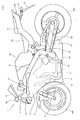
- Fig. 1 is a side view of a motorcycle 1 to which indicator-integrated rearview mirrors according to the embodiment of the present invention are attached.
- a pair of front forks 3 to which a front wheel WF is rotatably journalled under a front fender 5 are attached to a front end of a main frame 2 so as to be steerable with a handlebar 4.
- a swing arm 21 to which a rear wheel WR as a drive wheel is rotatably journalled and which is suspended by the vehicle body through a rear cushion 20 is swingably journalled about a pivot shaft 15.
- An engine 11 as a drive source is arranged under the main frame 2, and the rotational drive power is transmitted to the rear wheel WR through a drive chain 22.
- Combustion gas exhausted from the engine 11 is introduced to a muffler 14 in which an exhaust expansion chamber and a muffler are integrally formed on the lower side of the vehicle body, through exhaust pipes 12 each of which is provided for each cylinder.
- a fuel tank 10 is attached to an upper portion of the main frame 2, and a seat 16 on which a rider is seated and a seat cowl 17 are arranged behind the fuel tank 10.
- a taillight unit 23, a rear-side indicator system 18, and a rear fender 19 are attached behind the seat cowl 17.
- An upper cowl 7 to which a head light 8 and a wind screen 9 are attached is arranged ahead of a pair of left and right side cowls 6 which cover the engine 11 and a radiator 13. Between the head light 8 and the wind screen 9 of the upper cowl 7, left and right indicator-integrated rearview mirrors 30 according to the embodiment of the present invention are attached in pairs.
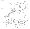
- Fig. 2 is a perspective view of one of the indicator-integrated rearview mirrors 30 according to the embodiment.
- the indicator-integrated rearview mirrors 30 are formed in bilaterally-symmetrical shapes, and therefore the explanation will be given to only the left mirror.
- the indicator-integrated rearview mirror 30 is configured by a front housing 31, a rear housing 32, an indicator system 33, and a mirror part 35, and is attached to the upper cowl 7 through an attachment plate 34.
- Figs. 3(a) and 3(b) are a top view and a side view of the indicator-integrated rearview mirror 30, respectively.
- the front housing 31 and the rear housing 32 which are divided in the front-rear direction of the vehicle body and which are engaged with each other to form a housing for the rearview mirror are formed by using thin plates made of resin.
- the indicator system 33 is supported by the front housing 31 in such a manner that only a light emitting part faces outside from a window part formed in the front housing 31.
- the mirror part 35 is supported by the rear housing 32 in such a manner that the angle thereof relative to the rear housing 32 can be adjusted.
- Attachment bolts 34a which are allowed to penetrate the upper cowl 7 to be fitted into tightening nuts (not shown) by screwing are embedded in the attachment plate 34.
- the attachment plate 34 is not engaged with the front housing 31, but is engaged with only an edge of the rear housing 32.
- Fig. 4 is a cross sectional view taken along the line A-A of Fig. 3 (a).
- the indicator system 33 is configured in such a manner that a casing 71 for supporting an indicator bulb 74 is covered with an indicator lens 70.
- An attachment part 72 is formed in the casing 71, and the indicator system 33 is fixed to the front housing 31 in such a manner that a tapping screw 76 is allowed to penetrate the attachment part 72 so as to be tightened with an attachment boss 40 formed on a back surface of the front housing 31, so that only the indicator lens 70 faces outside from the window part.
- a hole part 32a which is configured by integrally forming a cylindrical part 36 and a spherical-shaped engaging protrusion 37 formed at a tip end of the cylindrical part 36 is formed at a substantially middle portion of the rear housing 32.
- the mirror part 35 is configured in such a manner that a reflecting mirror 60 is attached to a base 50 made of resin.
- the engagement of a cylindrical part 51 having an engaging concave part formed at a substantially middle portion of the base 50 with the engaging protrusion 37 allows the mirror part 35 to be supported by the rear housing 32, so that the angle thereof relative to the rear housing 32 can be adjusted.
- FIGs. 5(a) and 5(b) are a front view and a side view of the attachment plate 34, respectively, and Fig. 6 is a cross sectional view taken along the line C-C of Fig. 5(a).
- a through-hole 81 is provided at a substantially middle portion of a body part 80 made of resin.
- a circular-shaped thin-walled part 82 is formed around the through-hole 81, and a groove part 83 having a substantially fan shape is formed at the bottom of the thin-walled part 81.
- a cylindrical part 84 is formed on a surface opposite to the surface on which the thin-walled part 82 is formed, and an inner circumference part 84a of the cylindrical part 84 is configured to be in communication with the through-hole 81.
- the attachment bolts to be fitted into the nuts by screwing are embedded in the body part 80 in the embodiment. However, the bolts may be pins or the like to be engaged with engaging members such as clips.
- Fig. 7 is a cross sectional view taken along the line B-B of Fig. 3 (b), and shows a state of being engaged with the rear housing 32.
- a bottom plate 47 of the rear housing 32 has a convex shape to correspond to the thin-walled part 82 and the groove part 83, and is engaged with the body part 80 in such a manner that a collar head pin 85 is allowed to penetrate the both, and then a clip 87 is attached to one end of the collar head pin 85 while biasing a coil spring 86 inserted into the cylindrical part 84.
- the rear housing 32 is normally held at a predetermined position of the attachment plate 34 fixed to the vehicle body, and can be rotated from the predetermined position by applying a force against the biasing force of the coil spring 86.
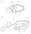
- Figs. 8(a) and 8(b) are a rear view and a bottom view of the front housing 31, respectively.
- the front housing 31 has a configuration in which an indicator system accommodation part 45 having the indicator system 33 accommodated and a cover part 46 serving as a cover of the rear housing 32 are integrally formed.
- Fig. 9 is a front view of the rear housing 32.
- the rear housing 32 has a configuration in which a mirror accommodation part 38 having the mirror part 35 accommodated and an attachment stay part 39 attached to the vehicle body are integrally formed.
- a plane part 38a facing the front housing 31 is formed in the mirror accommodation part 38, and first locking holes 41 a to be engaged with the first locking pawls 41 are formed at edges of the plane part 38a.
- In the attachment stay part 39 there are formed second locking holes 42a to be engaged with the second locking pawls 42, a third locking hole 43a to be engaged with the third locking pawl 43, and a fourth locking pawl 44a to be engaged with the fourth locking hole 44.
- Figs. 10(a) and 10(b) are perspective views of the rear housing 32 viewed from two directions.
- the attachment stay part 39 has a cross section in a substantially semicircular shape, and is engaged with the cover part 46 of the front housing 31, thus configuring a rearview mirror stay having a cross section in a substantially circular shape.
- a thick-walled part 52 to be engaged with the thin-walled part 82 and a protrusion part 53 in a substantially fan shape to be engaged with the groove part 83 are formed on a surface of the bottom plate 47 to be engaged with the attachment plate 34.
- Figs. 11 (a) and 11 (b) are a front view of the mirror part 35 and a cross sectional view taken along the line F-F of Fig. 11 (a), respectively.
- the cylindrical part 51 in which an engaging concave part 51 a having a spherical shape is formed at a portion thereof is formed at a substantially middle portion of the base 50.
- An extending wall 50a formed on one surface of the base 50 abuts on the plane part 38a of the front housing 31 at the time of adjusting the angle of the mirror part 35, so that the extending wall 50a has a function in which a range of adjustment is fallen within a predetermined range, and intrusion of water or dust into the engaging concave part 51 a is prevented.
- Fig. 12 is a cross sectional view taken along the line D-D of Fig. 8(a).
- the first locking pawl 41 having a hook shape formed in the indicator system accommodation part 45 of the front housing 31 is engaged with the first locking hole 41 a formed at an edge of the plane part 38a of the mirror accommodation part 38 of the rear housing 32.
- the other locking pawls and locking holes are the same in shape, and the front housing 31 and the rear housing 32 can be decomposed without using any tools in such a manner that the front housing 31 is bent to release the engagement of each locking pawl and locking hole.
- Figs. 13 and 14 are a front view of the indicator system 33 and a cross sectional view taken along the line H-H of Fig. 13, respectively.
- the indicator system 33 is configured in such a manner that a socket 73 with which the indicator bulb 74 is engaged is inserted into an attachment hole provided in the casing 71, and one lateral face of the casing 71 is covered with the indicator lens 70.
- the indicator system 33 is fixed to the front housing 31 in such a manner that the tapping screw 76 (see Fig. 4) is allowed to penetrate the attachment part 72 formed in the casing 71, and then is tightened with the attachment boss 40 formed on a back surface of the front housing 31.
- the socket 73 to which a wire 75 is connected can be detached from the casing 71, for example, only by turning the same with a hand by a predetermined angle without using any tools. As described above, since none of tools are required for the attachment and detachment work of the front housing 31 to/from the rear housing 32, it is possible to exchange the indicator bulb 74 without using any tools in a state where the indicator-integrated rearview mirror 30 is assembled.
- the housing of the rearview mirror is divided into two of the front housing and the rear housing which are made of resin, the indicator system is supported by the front housing, and the mirror part is supported by the rear housing.
- the front housing and the rear housing are attached to each other by engagement of the locking pawls and the locking holes which are formed in the both housings.
- none of tightening members such as screws are required.
- the outline shapes of the front housing, the rear housing, the indicator system, and the mirror part, and the arrangement positions and the number of the locking pawls and the locking holes of the front housing and the rear housing are not limited to the above-described embodiment, but various modifications can be made.
- the light emitting source of the indicator system may be configured using a plurality of light-emitting diodes in place of an incandescent bulb.
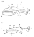
- Figs. 15 and 16 are a perspective view and a top view of an indicator-integrated rearview mirror 90 according to a second embodiment of the present invention, respectively.
- the indicator-integrated rearview mirror 90 is configured by a front housing 91, a mirror holding part 92, an attachment stay 93, an indicator system 150, and a mirror part 95, and is attached to the vehicle body through an attachment plate 96 fixed to the attachment stay 93.
- the mirror holding part 92 which supports the mirror part 95 while the angle thereof can be adjusted and the attachment stay.93 to be coupled to the mirror holding part 92 configure a rear housing 94 which faces the front housing 91. Accordingly, different materials can be used for the mirror holding part 92 and the attachment stay 93.
- the mirror holding part 92 is formed using resin
- the attachment stay 93 is formed using aluminum that is harder than resin.
- the rear housing 94 is divided into two and only a portion closer to the attachment part attached to the vehicle body is increased in strength. Accordingly, it is possible to increase the strength by which the indicator-integrated rearview mirror 90 is supported on the vehicle body-side while minimizing an increase in weight and manufacturing cost. Further, since the strength on the attachment part-side attached to the vehicle body is increased, a demand of increasing in strength the components on the tip end-side, that is, the mirror holding part 92 and the front housing 91 is decreased. Thus, it is possible to lighten the weight of the whole mirror by reducing the thicknesses of these components. It should be noted that the attachment stay 93 may be formed using metal, other than aluminum, or carbon.
- the indicator system 150 is supported by the front housing 91 in such a manner that only a light emitting part thereof faces outside from a window part formed in the front housing 91, and a power cord 152 to be connected to an indicator bulb 151 is coupled to a vehicle-body-side power source by passing through a space formed between the front housing 91 and the attachment stay 93.
- Fig. 17 is a top view of the indicator-integrated rearview mirror 90 in a state where the front housing 91 and the indicator system 150 are detached therefrom.
- the rear housing 94 is configured in such a manner that the attachment stay 93 and the mirror holding part 92 are tightened together with a bolt 110.
- the front housing 91 and the rear housing 94 are attached to each other mainly by engagement of engaging pawls (not shown) formed in the front housing 91 with engaging holes 92a formed in the mirror holding part 92.
- the attachment stay 93 and the attachment plate 96 are formed as an integral component made of aluminum. However, different materials may be used for the both as different components.
- the mirror part 95 is configured in such a manner that a reflecting mirror 99 is attached to a base 98 made of resin.
- a spherical-shaped concave part (not shown) formed at a substantially middle portion of the base 98 is engaged with a spherical-shaped convex part (not shown) formed in the mirror holding part 92, so that the mirror part 95 is supported while the angle thereof can be adjusted.
- Fig. 18 is a view viewed from the G direction of Fig. 17.
- Fig. 19 is a cross sectional view taken along the line H-H of Fig. 18.
- the attachment stay 93 is coupled to the mirror holding part 92 in such a manner that two columnar-shaped protrusions 93a having a screw hole formed on the attachment stay 93 are inserted into a through-hole formed in the mirror holding part 92, and the both are tightened together with the bolt 110.
- Fig. 20 is a front view of the indicator system 150.
- Fig. 21 is a cross sectional view taken along the line J-J of Fig. 20.
- the indicator system 150 is tightened to a back surface of the front housing 91 using screws (not shown).
- the indicator system 150 is configured in such a manner that a casing 154 which supports an indicator bulb 151 that is configured by an incandescent bulb and a position lamp bulb 156 that is configured by an LED is covered with a transparent indicator lens 153 with or without color.
- a shielding plate 155 by which lights or flashing lights of the both bulbs do not interfere with each other.
- the shapes of the front housing, the rear housing including the attachment stay and the mirror holding part, the indicator system, and the mirror part, and the materials of the attachment stay and the mirror holding part can be variously modified.
- the invention is directed to an indicator-integrated rearview mirror for a vehicle in which the number of components can be cut down to simplify and lighten the structure thereof.
- a housing of a rearview mirror is divided into two of a front housing 31 and a rear housing 32 which are made of resin, an indicator system 33 is supported by the front housing 31, and a mirror part 35 is supported by the rear housing 32.
- the both housings 31 and 32 are attached to each other by engagement of locking pawls with locking holes.
- a plane part facing the front housing 31 is formed in the rear housing 32, and the locking holes are formed at edges of the plane part.
- a spherical-shaped engaging part which supports the mirror part 35 while the angle thereof can be adjusted is formed integrally with the rear housing 32.
- the rear housing 32 is configured by integrally forming an accommodation part for the mirror part 35 and an attachment stay part attached to the vehicle body-side
- the front housing 31 is configured by integrally forming an accommodation part for the indicator system 33 and a cover for covering the attachment stay part.
Landscapes
- Engineering & Computer Science (AREA)
- Mechanical Engineering (AREA)
- Multimedia (AREA)
- Lighting Device Outwards From Vehicle And Optical Signal (AREA)
- Rear-View Mirror Devices That Are Mounted On The Exterior Of The Vehicle (AREA)
Applications Claiming Priority (2)
| Application Number | Priority Date | Filing Date | Title |
|---|---|---|---|
| JP2006244086 | 2006-09-08 | ||
| JP2007136608A JP5004012B2 (ja) | 2006-09-08 | 2007-05-23 | 車両のウィンカ一体型バックミラー |
Publications (2)
| Publication Number | Publication Date |
|---|---|
| EP1897792A1 true EP1897792A1 (de) | 2008-03-12 |
| EP1897792B1 EP1897792B1 (de) | 2009-10-21 |
Family
ID=38805715
Family Applications (1)
| Application Number | Title | Priority Date | Filing Date |
|---|---|---|---|
| EP07015112A Active EP1897792B1 (de) | 2006-09-08 | 2007-08-01 | Seitenrückspiegel mit angebrachtem Blinker für ein Fahrzeug |
Country Status (4)
| Country | Link |
|---|---|
| US (1) | US8272753B2 (de) |
| EP (1) | EP1897792B1 (de) |
| JP (1) | JP5004012B2 (de) |
| DE (1) | DE602007002857D1 (de) |
Cited By (1)
| Publication number | Priority date | Publication date | Assignee | Title |
|---|---|---|---|---|
| EP2949554A1 (de) * | 2014-05-30 | 2015-12-02 | Yamaha Hatsudoki Kabushiki Kaisha | Spiegelvorrichtung mit Blinkerlampe und Kraftfahrzeug mit Spiegelvorrichtung |
Families Citing this family (10)
| Publication number | Priority date | Publication date | Assignee | Title |
|---|---|---|---|---|
| JP2009107563A (ja) * | 2007-10-31 | 2009-05-21 | Yamaha Motor Co Ltd | 自動二輪車のサイドミラー、及び自動二輪車 |
| JP5150399B2 (ja) * | 2008-07-31 | 2013-02-20 | 本田技研工業株式会社 | 自動二輪車 |
| JP5383518B2 (ja) * | 2010-01-08 | 2014-01-08 | 本田技研工業株式会社 | 鞍乗型車両のバックミラー装置 |
| JP5687851B2 (ja) * | 2010-06-07 | 2015-03-25 | 川崎重工業株式会社 | 乗物の配線構造 |
| JP5562125B2 (ja) * | 2010-06-07 | 2014-07-30 | 川崎重工業株式会社 | バックミラー装置 |
| JP6240984B2 (ja) * | 2014-09-30 | 2017-12-06 | 本田技研工業株式会社 | 自動二輪車の車体前部構造 |
| CN105365953A (zh) * | 2015-10-27 | 2016-03-02 | 无锡尊宝电动车有限公司 | 一种耐磨型电动车后视镜 |
| JP6911065B2 (ja) | 2019-01-23 | 2021-07-28 | 本田技研工業株式会社 | ポジションライト一体型ウィンカ装置 |
| JP2023055459A (ja) * | 2021-10-06 | 2023-04-18 | カワサキモータース株式会社 | ミラー装置及び鞍乗り型乗物 |
| CN116409410B (zh) * | 2021-12-29 | 2026-01-27 | 浙江春风动力股份有限公司 | 摩托车 |
Citations (3)
| Publication number | Priority date | Publication date | Assignee | Title |
|---|---|---|---|---|
| GB1172382A (en) * | 1966-11-23 | 1969-11-26 | Shigeru Maruyama | A Vehicle Rear-View Mirror Combined with a Flashing Turn Indicator |
| JPH04325386A (ja) * | 1991-04-23 | 1992-11-13 | Honda Motor Co Ltd | バックミラー装置 |
| EP1428745A2 (de) * | 2002-12-09 | 2004-06-16 | HONDA MOTOR CO., Ltd. | Aufbau eines Rückspiegels |
Family Cites Families (9)
| Publication number | Priority date | Publication date | Assignee | Title |
|---|---|---|---|---|
| US5823654A (en) * | 1993-02-01 | 1998-10-20 | Donnelly Corporation | Universal exterior vehicle security light |
| US5499169A (en) * | 1995-05-16 | 1996-03-12 | Chen; Chun-Ming | Rearview mirror lamp circuit assembly |
| JP4247375B2 (ja) * | 1998-11-30 | 2009-04-02 | 株式会社ホンダロック | 車両用ミラー |
| DE20001407U1 (de) * | 2000-01-27 | 2000-03-16 | Reitter & Schefenacker GmbH & Co. KG, 73730 Esslingen | Außenrückblickspiegel für Fahrzeuge, vorzugsweise für Kraftfahrzeuge |
| TW479120B (en) * | 2000-05-29 | 2002-03-11 | Jia-Rung Jang | Rear mirror with indicating light and its fabricating method |
| JP2002337604A (ja) * | 2001-05-16 | 2002-11-27 | Ishizaki Honten:Kk | 車両用サイドミラー |
| JP2002362222A (ja) * | 2001-05-31 | 2002-12-18 | Tokai Rika Co Ltd | アウタミラーのターンシグナル付きバイザカバー構造 |
| US6811288B2 (en) * | 2001-06-29 | 2004-11-02 | Donnelly Corporation | Sideview mirror assembly with utility features |
| US6932497B1 (en) * | 2003-12-17 | 2005-08-23 | Jean-San Huang | Signal light and rear-view mirror arrangement |
-
2007
- 2007-05-23 JP JP2007136608A patent/JP5004012B2/ja active Active
- 2007-08-01 EP EP07015112A patent/EP1897792B1/de active Active
- 2007-08-01 DE DE602007002857T patent/DE602007002857D1/de active Active
- 2007-08-31 US US11/896,427 patent/US8272753B2/en not_active Expired - Fee Related
Patent Citations (3)
| Publication number | Priority date | Publication date | Assignee | Title |
|---|---|---|---|---|
| GB1172382A (en) * | 1966-11-23 | 1969-11-26 | Shigeru Maruyama | A Vehicle Rear-View Mirror Combined with a Flashing Turn Indicator |
| JPH04325386A (ja) * | 1991-04-23 | 1992-11-13 | Honda Motor Co Ltd | バックミラー装置 |
| EP1428745A2 (de) * | 2002-12-09 | 2004-06-16 | HONDA MOTOR CO., Ltd. | Aufbau eines Rückspiegels |
Cited By (1)
| Publication number | Priority date | Publication date | Assignee | Title |
|---|---|---|---|---|
| EP2949554A1 (de) * | 2014-05-30 | 2015-12-02 | Yamaha Hatsudoki Kabushiki Kaisha | Spiegelvorrichtung mit Blinkerlampe und Kraftfahrzeug mit Spiegelvorrichtung |
Also Published As
| Publication number | Publication date |
|---|---|
| US8272753B2 (en) | 2012-09-25 |
| JP5004012B2 (ja) | 2012-08-22 |
| DE602007002857D1 (de) | 2009-12-03 |
| JP2008087755A (ja) | 2008-04-17 |
| EP1897792B1 (de) | 2009-10-21 |
| US20080062544A1 (en) | 2008-03-13 |
Similar Documents
| Publication | Publication Date | Title |
|---|---|---|
| EP1897792B1 (de) | Seitenrückspiegel mit angebrachtem Blinker für ein Fahrzeug | |
| US9593817B2 (en) | Headlight device of motorcycle | |
| US10391925B2 (en) | Vehicle headlight with a plurality of inner non spherical lenses transmitting light from a high beam and a low beam light source | |
| CN101497323B (zh) | 车辆的后部照明装置 | |
| JP6489595B2 (ja) | 補助照明を備える灯火器構造 | |
| JP5335760B2 (ja) | 自動二輪車の灯火装置 | |
| JP2006114249A (ja) | 車両のテールランプ構造 | |
| CN1248900C (zh) | 机动两轮车用前大灯 | |
| EP1361145B1 (de) | Rücklichtvorrichtung für Motorrad | |
| EP2949554B1 (de) | Spiegelvorrichtung mit Blinkerlampe und Kraftfahrzeug mit Spiegelvorrichtung | |
| JP4290514B2 (ja) | ウインカ装置 | |
| EP2796318A1 (de) | Heckleuchtenvorrichtung für ein Fahrzeug | |
| CN111605653B (zh) | 鞍乘型车辆 | |
| JP5171518B2 (ja) | 自動二輪車のヘッドライト装置 | |
| JP6719524B2 (ja) | 鞍乗型車両のウインカランプ取付構造 | |
| JP5383518B2 (ja) | 鞍乗型車両のバックミラー装置 | |
| WO2020066138A1 (ja) | 鞍乗型車両のライセンスライト | |
| JP5952144B2 (ja) | 灯火器構造 | |
| JP4447268B2 (ja) | ヘッドランプカバー | |
| JP2007149536A (ja) | 車両用灯火装置 | |
| EP1780104B1 (de) | Eingebaute Blinkerstruktur | |
| CN223990103U (zh) | 骑乘型车辆的光源支撑构造 | |
| JP4641467B2 (ja) | 自動二輪車の後部構造 | |
| JP5235179B2 (ja) | 車両用灯火器 | |
| JP2009056892A (ja) | 二輪車用灯火器 |
Legal Events
| Date | Code | Title | Description |
|---|---|---|---|
| PUAI | Public reference made under article 153(3) epc to a published international application that has entered the european phase |
Free format text: ORIGINAL CODE: 0009012 |
|
| 17P | Request for examination filed |
Effective date: 20070801 |
|
| AK | Designated contracting states |
Kind code of ref document: A1 Designated state(s): AT BE BG CH CY CZ DE DK EE ES FI FR GB GR HU IE IS IT LI LT LU LV MC MT NL PL PT RO SE SI SK TR |
|
| AX | Request for extension of the european patent |
Extension state: AL BA HR MK YU |
|
| AKX | Designation fees paid |
Designated state(s): DE IT |
|
| GRAP | Despatch of communication of intention to grant a patent |
Free format text: ORIGINAL CODE: EPIDOSNIGR1 |
|
| GRAS | Grant fee paid |
Free format text: ORIGINAL CODE: EPIDOSNIGR3 |
|
| GRAA | (expected) grant |
Free format text: ORIGINAL CODE: 0009210 |
|
| RAP1 | Party data changed (applicant data changed or rights of an application transferred) |
Owner name: HONDA MOTOR CO., LTD. |
|
| AK | Designated contracting states |
Kind code of ref document: B1 Designated state(s): DE IT |
|
| REF | Corresponds to: |
Ref document number: 602007002857 Country of ref document: DE Date of ref document: 20091203 Kind code of ref document: P |
|
| PLBE | No opposition filed within time limit |
Free format text: ORIGINAL CODE: 0009261 |
|
| STAA | Information on the status of an ep patent application or granted ep patent |
Free format text: STATUS: NO OPPOSITION FILED WITHIN TIME LIMIT |
|
| 26N | No opposition filed |
Effective date: 20100722 |
|
| PGFP | Annual fee paid to national office [announced via postgrant information from national office to epo] |
Ref country code: FI Payment date: 20180829 Year of fee payment: 8 |
|
| REG | Reference to a national code |
Ref country code: DE Ref legal event code: R084 Ref document number: 602007002857 Country of ref document: DE |
|
| PG25 | Lapsed in a contracting state [announced via postgrant information from national office to epo] |
Ref country code: IT Free format text: LAPSE BECAUSE OF NON-PAYMENT OF DUE FEES Effective date: 20190801 |
|
| PGFP | Annual fee paid to national office [announced via postgrant information from national office to epo] |
Ref country code: DE Payment date: 20250724 Year of fee payment: 19 |